Creating an interactive grass in the Unreal Engine
Until recently, grass in games was usually marked by texture on the ground, rather than by rendering individual stems. But with the increase in iron power, it became possible to render grass. Remarkable examples of such rendering can be seen in games like Horizon Zero Dawn and The Legend of Zelda: Breath of the Wild . In these games, the player can roam grassy meadows, and, more importantly, the grass reacts to the player’s actions.
Fortunately, creating such a system is not very difficult. Actually, the article will teach you exactly that! In this tutorial you will learn the following:
- Create a vector field using scene capture and particle systems
- Bend the grass from the player based on the vector field
Note: in this tutorial it is assumed that you already know the basics of working with the Unreal Engine. If you are new to the Unreal Engine, then learn our series of tutorials from ten parts of the Unreal Engine for beginners . In particular, look at the particle system tutorial to know how to use Cascade in this tutorial.
Note: this tutorial belongs to a series of three tutorials on working with render targets:
')
- Part 1: Drawing with Render Targets
- Part 2: Warped Snow
- Part 3: interactive grass
Getting Started
Let's start by downloading materials for this tutorial (you can download them from here ). Unzip them, go to InteractiveGrassStarter and open InteractiveGrass.uproject . You will see a small field of grass that will be the topic of this tutorial. I also created a widget to display the render target scene capture.
Before you begin, you should study the tutorial on creating footprints in the snow , because I will skip some of the information. It is worth considering that in this tutorial is also used capture and projection. To save time, I prepared a blueprint of capture, similar to the blueprint of the tutorial on the trail in the snow.
First, let's look at another way to create interactive grass. The most common way is to transfer the player’s coordinates to the grass material and to use a spherical mask to bend the grass within a certain radius from the player.
Although this approach is quite good, it doesn’t scale well when we want to add more actors to the grass. For each actor being added to the material, you will have to add one more coordinate parameter and a spherical mask. A more scalable method is to use a vector field .
What is a vector field?
A vector field is simply a texture, each pixel of which corresponds to a direction. If you have previously worked with stream maps, they are similar. But instead of moving the UV, we’ll use the World Position Offset contact to move the vertices. Unlike the solution with a spherical mask, to obtain the direction of bending, it is sufficient to sample the vector field only once .
Let's find out how you can save directions in a texture. Look at this grid:

Suppose a red dot is an object that we want to move. If we move it to the lower right corner, which vector will represent this movement? If you answered (1, 1) , then you are right! As you probably know, you can also represent the vectors as flowers, and thus save them to a texture. Let's insert this vector into the Unreal color picker and see what color it returns.
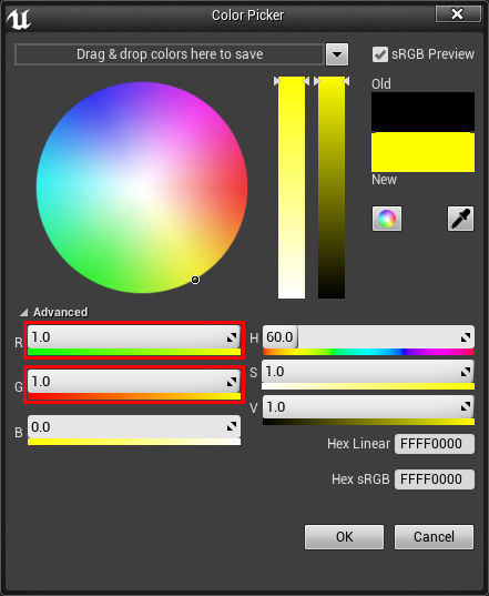
As you can see, the direction (1, 1) returns yellow. This means that if we want to bend the grass in the direction of the positive XY axes, then we will have to use this texture color. Let's now look at the colors of all vectors.
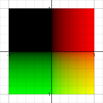
The lower right square looks pretty good because it has gradients along both axes. This means that we can store any vector in the color of this quadrant, because each vector has a unique color.
But with the other three quadrants a problem arises. We have a gradient along only one axis, or no gradient at all. This means that several vectors will have the same color. For example, we can not distinguish between the vectors (-1, 1) and (0, 1) .
These three quadrants do not have unique colors for each vector because we can only represent colors using values from 0 to 1. However, these three quadrants use negative values outside this interval.
The solution is to redistribute the vectors so that they all fit in the interval from 0 to 1. This can be done by multiplying the vector by 0.5 and adding 0.5 . Here is a visualization of what we get:
Now each vector has a unique color. When we need to use it for calculations, we simply redistribute it back to the interval from -1 to 1. Here are a few colors, and the corresponding directions after the redistribution:
- (0, 0): Negative X and Y
- (0.5, 0.5): no movement
- (0, 1): Negative X and Positive Y
- (1, 0): positive X and negative Y
Now let's learn how to create a vector field in Unreal.
Creating a vector field
Unlike creating tracks in the snow, we will not capture the shape of objects. Instead, we will paint on the render target using “brushes”. These will be just the images of the selected vector field. I will call them directions brushes .
Instead of drawing on the render target using blueprints, we can use particles . Particles will display brush directions and be emitted from the player. To create a vector field, we just need to use scene capture and capture only particles. The advantage of this method is that creating traces is very simple. In addition, it allows you to easily manage such properties as the duration of the preservation of traces and their size. In addition, the particles create temporarily remaining traces, because they exist after leaving the capture area and returning to it.
Below are a few examples of brush patterns that we can use, as well as their influence on the grass. Notice that in the example shown below the particles are invisible.

To begin, let's create a material that will display a brush of directions.
Creating material for referrals
There are two ways to create brush directions:
- Mathematical: Directions and shape are defined inside the material. Its advantage is that it does not require third-party software and is convenient for simple forms.
- Transformation of the normal map: creating a normal map of the desired directions and shape. To convert the map into a suitable vector field, we just need to remove the blue channel. The advantage of this method is that you can very easily create complex shapes. Below is an example of a brush that will be difficult to create mathematically.
For this tutorial we will create a brush mathematically. Go to the Materials folder and open M_Direction . Note that the shading model Unlit is selected for this material. This is important because it allows the capture of a scene to capture particles without affecting them.
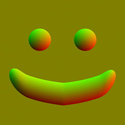
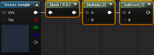
In order not to complicate things, we will create a material that will force the grass to move away from the center of the particle. To do this, create the following scheme:
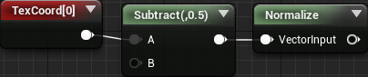
Now we need to perform a redistribution. To do this, add the selected nodes and connect everything as follows:
Now let's make the brush round. To do this, add the selected nodes:
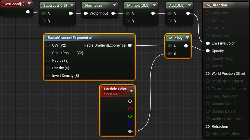
RadialGradientExponential controls the size and sharpness of a circle's circumference. Multiplying it by Particle Color allows you to control the opacity of particles from a particle system. I will talk more about this in the next section.
Here is what the brush looks like:

Click Apply and close the material. Now that we have created the material, it is time to start on the particle trail system.
Creating a trace particle system
Go to the ParticleSystems folder and open PS_GrassTrail . To save time, I have already created all the necessary modules.

Here is how each module affects traces on the grass:
- Spawn: the frequency of creation affects the smoothness of the tracks. If the traces look intermittent, then it is worth increasing the frequency of creation. In this tutorial we will leave the default value (20).
- Lifetime: the lifetime of the track until the grass returns to its original state
- Initial Size: track size
- Color Over Life: as we use in the Particle Color material, here you can control the opacity. You can also change the alpha curve to control the disappearance of the trace. For example, you can choose linear loss, easing in and / or easing out. In this tutorial, we will leave the default setting, that is, linear disappearance.
- Lock Axis: used to direct particles toward the scene.
- Initial Rotation: used to ensure that the particles are oriented along the correct axes (more on this below)
First we need to set the material. Select the Required module and set the Material to M_Direction . Also set the Sort Mode to PSORTMODE Age Newest First .

This sorting mode allows you to render new particles on top of old ones. If this is not done, then the grass will be affected not by new, but by old particles.
Next is the duration of the trace. Select the Lifetime module and set the Constant value to 5 . Due to this, the trail will disappear within five seconds.

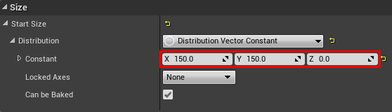
We now turn to the size of the track. Select the Initial Size module and set the Constant value to (150, 150, 0) . Due to this, each particle will cover an area of 150 × 150.
Now we need to make it look in the direction of the capture scene. Since the scene capture will be executed from a top view, the particles should look in the direction of the positive Z axis. To do this, select the Lock Axis module and set the Lock Axis Flags value to Z.

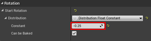
Finally, we need to set the rotation of the particles. Currently, brush colors are not aligned with the direction they represent. It happened because the default particle system is applied with a rotation of 90 degrees. To fix this, select the Initial Rotation module and set the Constant value to -0.25 . This will rotate the particles 90 degrees counterclockwise.
And that's all we need for a particle system, so let's close it.
Next, we need to attach a particle system to what should create traces. In our case, you need to attach it to the player's character.
Attaching a particle system
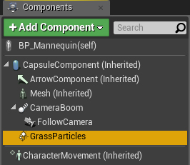
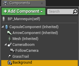
Go to Characters \ Mannequin and open BP_Mannequin . Next, create the Partice System component and name it GrassParticles .
Next we need to set the particle system. Go to the Details panel and set the Particles \ Template value to PS_GrassTrail .

It would be strange if the player could see the trail in the game, so it's worth hiding it. To do this, turn on Rendering \ Owner No See .

Since the particle system is attached to the player (owner), the player will not see it, but it will be visible to the rest.
Click Compile , and then click Play . Note that particles do not appear for the player’s camera, but are mapped to the render target.

While the capture scene is set to capture everything . Obviously, this does not suit us, because only particles affect the grass. In the next section, we will learn how to capture particles only.
Particle trapping
If we capture particles now, then bending that we do not need will be performed in areas without particles. This is because the render target background color is black. Bending occurs because black denotes movement towards the negative XY axes (after redistribution). In order for the empty areas to contain no movement, we need to make the render target background color (0.5, 0.5, 0) . The easiest way to do this is to create a huge plane and attach it to the player.
First create the material for the background. Return to the Content Browser and open the Materials \ M_Background . Then connect the constant (0.5, 0.5, 0) with Emissive Color .

Note: As with the particle material, any material that we will capture must have an unlit shading model .
Click Apply and close the material. Go back to BP_Mannequin , and then create a new Plane component. Call it Background .
Next, set the following properties:
- Location: (0, 0, -5000). We place the plane so low that it does not overlap any particles.
- Scale: (100, 100, 1). So we will scale to a size sufficient to cover the entire capture area.
- Material: M_Background

As in the case of particles, it would be strange if the player saw a huge yellow plane under him. To hide it, turn on Rendering \ Owner No See .

Now that we’ve set up the background, it’s time to grab the particles. We can do this by adding a particle system to the show-only list of the scene capture. This is a list of components that will capture a scene.
Using the Show-Only List
Before we get the opportunity to add to the show-only list, we need a way to get all the actors that influence the grass. One way to get them is to use tags . Tags are simple strings that can be assigned to actors and components. Then you can use the node Get all Actors With Tag to get all the actors with the corresponding tag.
Since the player's actor must influence the grass, it needs a tag. To add a tag, click on the Class Defaults button. Then create a new tag in Actor \ Tags and name it GrassAffector .

Since only components can be transferred to the show-only list, we need to add tags to the grass-affecting components. Select the GrassParticles component and add a new tag located in the Tags section. Call it GrassAffector too (it is not necessary to use this particular tag). Repeat the same for the Background component.

Now we need to add the grass-affecting components to the show-only list of the scene capture. Click Compile and close BP_Mannequin . Then open Blueprints \ BP_Capture . Go to Event BeginPlay and add highlighted nodes. Also ensure that the indicated pins are connected.
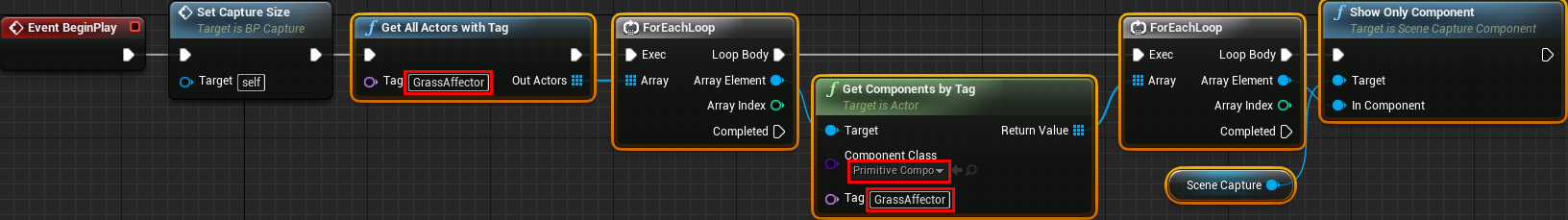
This scheme will bypass in the loop all the actors with the GrassAffector tag. After that, it will check if the actor has components with such a tag, and add them to the show-only list.
Next, we need to tell the capture scene to use only the show-only list. Select the SceneCapture component and go to the Scene Capture section. Set Primitive Render Mode to Use ShowOnly List .
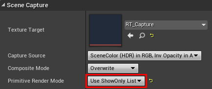
Click Compile and close the blueprint. If you click on Play , you will see that the render target now only captures particles and the background plane.

In the next section, we will get to what we expected. It is time to teach the grass to bend!
Bend the grass
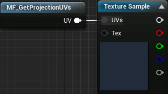
First we need to project the render target to the grass. Go to the Materials folder and open M_Grass . Then create the nodes shown below. Set RT_Capture as your texture.
Since we redistributed the colors in the interval from 0 to 1, before using them, you need to redistribute back to the interval from -1 to 1. To do this, add the selected nodes:
Now that we have a bending direction, we need some way to turn the grass in that direction. Fortunately, for this there is a node called RotateAboutAxis . Let's create it.

Let's start with the NormalizedRotationAxis contact. As the name implies, this is the axis around which the vertex will turn. To calculate, we just need the vector product of the direction of flexion by (0, 0, -1) . To do this, we need to add highlighted nodes:

We also need to specify the RotationAngle , that is, the amount of rotation of the vertex relative to the point of rotation. By default, the value should be in the range of 0 to 1, where 0 is 0 degrees and 1 is 360 degrees. To obtain the angle of rotation, we can use the length of the direction of flexion multiplied by the maximum rotation.

Multiplying by a maximum rotation of 0.2 means that the maximum rotation angle is 72 degrees.
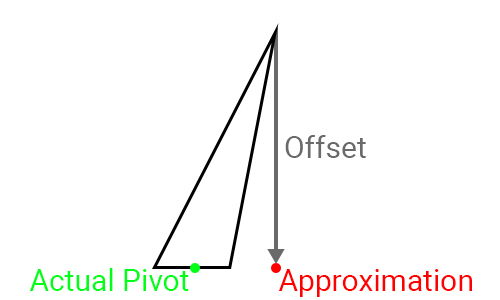
Calculating PivotPoint is a bit more difficult, because one mesh of grass contains several stems. This means that we cannot use something like the Object Position node, because it will return a single point for all the grass stems.
Ideally, use a third-party 3D editor to maintain the rotation points inside the UV channels. But for this tutorial we just approximate the pivot point. This can be done by moving from the top down to a certain offset.
To do this, add the selected nodes:
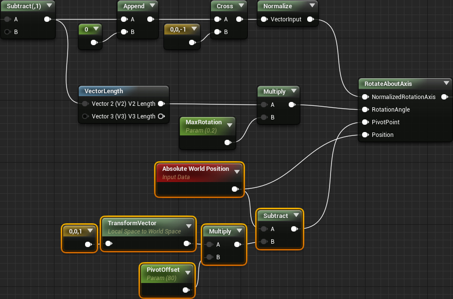
In this tutorial, the grass is about 80 units tall, so I set this value for PivotOffset .
Next we need to perform two masks. The first mask ensures that the stem root will not move. The second mask ensures that the vector field does not act on the grass outside the capture area.
Masking
For this tutorial, I set the colors of the grass tops in such a way that the bottom peaks are black and the top ones are white.

To mask the roots, we simply multiply the result of RotateAboutAxis by the Vertex Color node.

To mask the grass outside the capture area, we multiply the previous result by the selected node:

Click Apply and close the material. Click Play and run on the grass to leave traces on it!

Where to go next?
The finished project can be downloaded from here .
Although the method shown in the tutorial works fine for such simple objects as grass, it is not enough when using objects that require more dynamism. A partial solution to the problem is to use physical versions of foliage. More information is in this post about interactive foliage.
Finally, I want to thank Deathrey from the Unreal Engine community for suggesting this method with particles!
Source: https://habr.com/ru/post/420079/
All Articles