Drawing with Render Targets in the Unreal Engine
The render target is essentially a texture that can be written to while the application is running. From the point of view of the engine, they store information such as the base color, normals, and ambient occlusion.
From the user's point of view, the render target are mainly used as a kind of additional camera. You can set the scene capture at some point and save the image in the render target. You can then display the render target in the mesh, for example, to simulate a surveillance camera.
After the release of version 4.13 of the engine, Epic added the ability to draw materials directly to the render target using blueprints. This feature allows you to create complex effects, such as fluid simulation and snow deformation. Sounds amazing, right? But before moving on to such complex effects, it is best to get comfortable with something simple. What could be simpler than drawing on the render target?
')
In this tutorial you will learn the following:
- Dynamically create a render target using blueprints
- Show render target on mesh
- Draw texture on render target
- Change brush size and texture during gameplay
Note: this tutorial assumes that you are already familiar with the basics of working with the Unreal Engine. If you are new to the Unreal Engine, then learn our series of tutorials from ten parts of the Unreal Engine for beginners .
Getting Started
Let's start by downloading materials for this tutorial (you can take them here ). Unzip them, go to CanvasPainterStarter and open CanvasPainter.uproject . If you click Play , you will see the following:

The square in the middle (canvas) is what we will draw on. The UI elements on the left will be the texture that we will draw and its size.
To begin, let's deal with the way that is used for drawing.
Way of drawing
The first thing we need is the render target, which is used as the canvas. To determine where to draw on the render target, we trace the line that comes out of the camera forward. If the line crosses the canvas, then we can get the intersection in the UV-space.
For example, if the canvas has an ideal binding of UV-coordinates, then the intersection in the center will return the value (0.5, 0.5) . If the line crosses the canvas in the lower right corner, then we get the value (1, 1) . You can then use simple calculations to calculate the drawing location.
But why get coordinates in UV space? Why not use the coordinates of this space of the world? When using the space of the world, we first have to calculate the intersection with respect to the plane. Also have to take into account the rotation and scale of the plane.
When using UV space, all these calculations are not required. On a plane with an ideal reference of UV-coordinates, the intersection with the middle always returns (0.5, 0.5) , regardless of the location and rotation of the plane.
Note: The method discussed in this tutorial generally works only with planes or surfaces similar to planes. For other types of geometry, a more complex method is required, which I will discuss in another tutorial.
First we will create the material that will display the render target.
Creating canvas material
Go to the Materials folder and open M_Canvas .
In this tutorial, we will create the render target dynamically using blueprints. This means that we will have to adjust the texture as a parameter so that we can pass on its render target. To do this, create a TextureSampleParameter2D and name it RenderTarget . Then connect it to BaseColor .

Do not worry about choosing a texture yet - we will deal with this further in blueprints. Click Apply , and then close M_Canvas .
The next step is to create a render target, after which we use it as the canvas material.
Creating Render Target
There are two ways to create a render target. First: create in the editor by clicking on Add New \ Materials & Textures \ Render Target . This method allows you to conveniently refer to the same render target to several actors. However, if we need several canvases, we will have to create the render target manually for each canvas.
Therefore, it is better to create a render target using blueprints. The advantage of this approach is that we create render targets only when necessary and they do not inflate the size of the project files.
First we need to create a render target and save it as a variable for later use. Go to the Blueprints folder and open BP_Canvas . Find the Event BeginPlay and add highlighted nodes.

Set the Width and Height parameters to 1024 . So we change the render target resolution to 1024 × 1024 . The higher the values, the higher the image quality, but the higher the video memory costs.

Next comes the Clear Render Target 2D node. We can use this node to set the render target color. Set the Clear Color value (0.07, 0.13, 0.06) . At the same time, the entire render target will be filled with a greenish color.

Now we need to display the render target in the mesh of the canvas.
Render Target Mapping
At this stage, the canvas mesh uses the default material. To render the render target, you need to create a dynamic instance of M_Canvas and pass the render target to it. Then you need to apply a dynamic copy of the material to the canvas mesh. To do this, we add the selected nodes:

First, go to the node Create Dynamic Material Instance and set as the Parent value M_Canvas . So we will create a dynamic instance of M_Canvas .

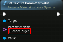
Next, go to the Set Texture Parameter Value node and set the Parameter Name value to RenderTarget . So we will pass the render target to the texture parameter created earlier.
Now the render target will be displayed on the canvas mesh. Click on Compile and return to the main editor. Click on Play to see how the canvas will change color.

Now that we have a canvas, we need to create a material that can be used as a brush.
Creating brush material
Go to the Materials folder. Create an M_Brush material and open it. First set the Blend Mode to Translucent . This will allow us to use textures with transparency.

As with the canvas material, we set the texture for the brush in blueprints. Create a TextureSampleParameter2D and name it BrushTexture . Connect it as follows:

Click on Apply , and then close M_Brush .
The next thing you need to do is create a dynamic copy of the brush material so that you can change the texture of the brush. Open BP_Canvas and add highlighted nodes.

Next, go to the Create Dynamic Material Instance node and set the Parent value to M_Canvas .

We created the brush material, and now we need a function to paint on the render target.
Paint on Render Target
Create a new function and name it DrawBrush . First we need the parameters: the texture used, the size of the brush and the place to draw. Create the following input data:
- BrushTexture: select type 2D Texture
- BrushSize: select float type
- DrawLocation: select type Vector 2D

Before drawing a brush, we need to set its texture. To do this, create the schema shown below. Make sure that the BrushTexture value is selected as the Parameter Name .

Now we need to perform a render in the render target. To do this, create the selected nodes:

Begin Draw Canvas to Render Target will allow the engine to know that we want to start drawing to a specific render target. Draw Material allows you to draw material at a specified location with the selected size and rotation.
Calculating a drawing position is a two-step process. First we need to scale the DrawLocation to fit in the render target resolution. To do this, multiply DrawLocation by Size .

By default, the engine will draw materials using the upper left corner as the starting point. Therefore, the brush texture will not be centered to us where we want to draw. To fix this, we need to divide the BrushSize by 2 , and then subtract the result from the previous step.

Then we connect everything as follows:

Finally, we need to tell the engine that we want to stop the rendering in the render target. Add the End Draw Canvas to Render Target node and connect it as follows:

Now, each time DrawBrush is executed , it will first set the transmitted texture as a texture for the BrushMaterial . Then it will draw the BrushMaterial in the RenderTarget using the position and size transferred.
And the drawing function is ready for this. Click on Compile and close BP_Canvas . The next step is to trace the line from the camera and draw at the place of the canvas where the intersection occurred.
Trace straight from camera
Before drawing on canvas, we need to specify the brush texture and size. Go to the Blueprints folder and open the BP_Player . Then we assign the value T_Brush_01 to the variable BrushTexture , and the value 500 to the variable BrushSize . So we will assign a monkey brush with a size of 500 × 500 pixels.

Next, you need to trace the line. Locate InputAxis Paint and create the following schema:

This way we will trace the line, directed straight from the camera, while the player holds down the key assigned to Paint (in our case, this is the left mouse button ).
Now we need to check whether the straight canvas has crossed. Add selected nodes:

Now, at the intersection of the line and the canvas, the DrawBrush function will be executed, using the brush variables and UV coordinates passed to it.
In order for the Find Collision UV node to work, we need to change two parameters. First, go to the LineTraceByChannel node and turn on the Trace Complex .

Second, go to Edit \ Project Settings , and then to Engine \ Physics . Turn on Support UV From Hit Results and restart the project.

After restarting for drawing on canvas, click Play and left mouse button .

You can even create several canvases and draw on each of them separately. This is possible because each canvas dynamically creates its own render target.

In the next section, we will implement the functionality for changing the size of the brush by the player.
Change brush size
Open BP_Player and locate the InputAxis ChangeBrushSize node. This axis reference is configured to use the mouse wheel . To change the size of the brush we just need to change the value of BrushSize depending on the Axis Value . To do this, create the following scheme:

It will add or subtract from BrushSize when the player uses the mouse wheel. The first multiplication determines the speed of addition or subtraction. Clamp (float) has been added as a security measure. It guarantees that the size of the brush will not be less than 0 or greater than 1000 .
Click on Compile and return to the main editor. Roll the mouse wheel to change the size of the brush while drawing.
In the last section, we will create a functional that allows the player to change the texture of the brush.
Change brush texture
First we need an array to store the textures that a player can use. Open BP_Player and create an array variable. Choose Texture 2D for it and name it Textures .

Then create three elements in Textures . Give them the following values:
- T_Brush_01
- T_Brush_02
- T_Brush_03

These will be the textures the player can draw with. To add new textures, just add them to this array.
Next, we need a variable to store the current index of the array. Create an integer variable and name it CurrentTextureIndex .

Next, we need a way to traverse all textures in the loop. For this tutorial, I set up an action mapping called NextTexture and attached it to the right mouse button . When a player presses this key, the transition to the next texture must be made. To do this, locate the InputAction NextTexture node and create the following schema:

This scheme will increase CurrentTextureIndex with each click on the right mouse button . If the index reaches the end of the array, it is again reset to 0 . Finally, BrushTexture is set to the corresponding texture.
Click on Compile and close the BP_Player . Click Play and right-click to switch between textures.

Where to go next?
The finished project can be downloaded from here .
Render target is an extremely powerful tool and in this tutorial we have touched only the very basics. If you want to know what render targets are capable of, see Content-Driven Multipass Rendering in UE4 . In this video, there are examples of drawing flow maps, volumetric drawing, fluid simulation, and more.
Also check out our Blueprint Drawing to Render Targets tutorial video to learn how to create a height map drawing tool using the render target.
Source: https://habr.com/ru/post/420031/
All Articles