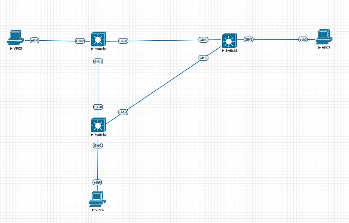
STP operation principle
Reason to create STP
The reason for creating the STP protocol was the occurrence of loops on the switches. What is a loop? The definition of a loop is:
Bridging loop (Switching loop) - a state in the network, in which there is an infinite transfer of frames between switches connected to the same network segment.
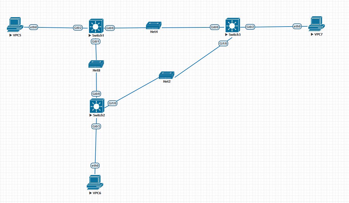
From the definition it becomes clear that the occurrence of a loop creates big problems - it leads to an overload of switches and inoperability of this network segment. How does the loop come about? The picture below shows the topology in which a loop will occur in the absence of any protective mechanisms:
')
The occurrence of a loop under the following conditions:
1. Any host sends a Broadcast frame:
- For example, VPC5 sends a packet with a broadcasted destination address.
- Having received this packet, Switch1 must send it through all ports, except for the port from which the packet came. The packet will be sent through the ports Gi0 / 0, Gi1 / 0.
- Switches Switch2, Switch3 accepting this packet will also have to send it a packet. Thus, Switch2, which received a packet from Switch1, will send it to Switch3, and Switch3 will send it to Switch2.
- Further, Switch2, receiving the packet from Switch3, sends it to Switch1, and Switch3, receiving the packet from Switch2, will also send it to Switch1. Thus, we come to step 1) and it will continue indefinitely. Everything is also aggravated by the fact that, at step 4), Switch1 will already have two frame instances, since it will receive them from both Switch2 and Switch3.
Steps 1) - 4) will be repeated indefinitely and on commutators this happens in a split second. Also, looping causes the MAC address table on the switches to constantly change and the MAC address of the sender of the VPC5 to be constantly assigned to either the Gi0 / 0 interface, the Gi1 / 0, or the Gi0 / 2 (if at that moment other packages). Such a cycle will lead to incorrect operation of the network and all switches. And sending broadcasts to hosts is common, as in the example ARP protocol.
2. A loop can also be formed without sending a broadcast frame.
- For example, VPC5 sends a frame with a unicast destination mac address.
- It is possible that the destination MAC address is not in the switch MAC address table. In this case, the switch will forward the packet through all ports, except the port from which it received the frame. And we get the same situation as with the Broadcast frame.
- Below we will look at the STP protocol on Cisco switches. They use STP separately for each vlan, protocol PVST +. We have only one vlan, so the meaning does not change.
STP Basics
The principle of operation of this protocol is based on the fact that all redundant links between switches are logically blocked and traffic is not transmitted through them. To build a topology without redundant channels, a tree is built (mathematical graph). To build such a tree, you first need to determine the root of the tree from which the graph will be built. Therefore, the first step of the STP protocol is to define the root switch (Root Switch). To determine the Root Switch, switches exchange BPDU messages. In general, the STP protocol uses two types of messages: BPDU — contains information about switches and TCN — notifies you of a topology change. Consider BPDU in more detail. Talk about TCN in more detail below. When STP is enabled on the switches, the switches begin to send BPDU messages. These messages contain the following information:
The BPDU frame has the following fields:
- The protocol version identifier STA (2 bytes). Switches must support the same version of the STA protocol.
- STP protocol version (1 byte)
- Type BPDU (1 byte). There are 2 types of BPDU - configuration and reconfiguration notification
- Flags (1 byte)
- Root Switch ID (8 bytes)
- The cost of the route to the root switch (Root Path Cost)
- Sender ID (Bridge ID) (8 bytes)
- Port identifier from which this packet is sent (Port ID) (2 bytes)
- Message Lifetime (2 bytes). Measured in units of 0.5 s, used to identify outdated messages.
- Maximum message lifetime (2 bytes). If a BPDU frame has a lifetime longer than the maximum, then the frame is ignored by the switches.
- Hello interval (2 bytes), the interval at which BPDU packets are sent
- Delay state transition (2 bytes). Minimum time for the switch to become active
The main fields that require special attention are the following:
- Sender ID (Bridge ID)
- Root Bridge ID (Root Bridge ID)
- Port ID from which this packet is sent (Port ID)
- The cost of the route to the root switch (Root Path Cost)
To determine the root switch, the Bridge ID is used. Bridge ID is a number of 8 bytes in length, which consists of Bridge Priority (priority, from 0 to 65535, by default 32768) and the MAC address of the device. The switch with the lowest priority is selected as the root switch; if the priorities are equal, then MAC addresses are compared (character-wise, the one that is less wins).
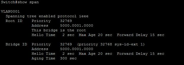
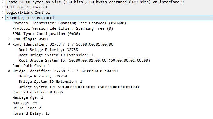
Here is the output of the Bridge ID information from the Switch1 switch from the first picture. Priority - 32769 (by default 32768 + Vlan Id), MAC addresses - Address 5000.0001.0000:
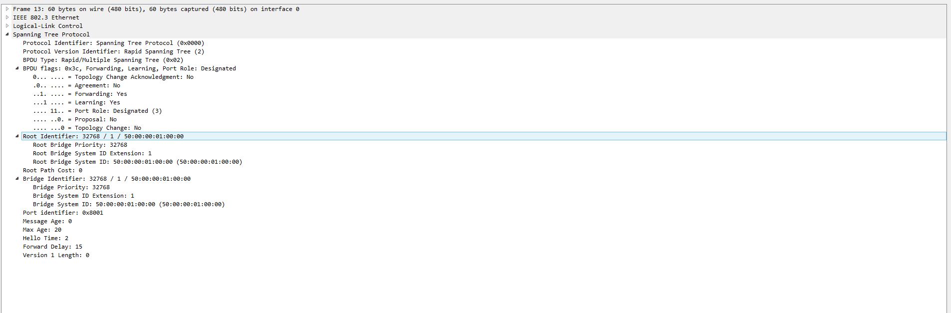
Imagine the picture, the switches just turned on and now begin to build a topology without loops. As soon as the switches are loaded, they begin sending out BPDUs, where they inform everyone that they are the root of the tree. In BPDU, as the Root Bridge ID, switches specify their own Bridge ID. For example, Switch1 sends BPDUs to Switch3, and Switch3 sends to Switch1. BPDU from Switch1 to Switch3:

BPDU from Switch3 to Switch1:
As we see from the Root Identifier, both commutators tell each other that it is he who is the Root switch.
Choosing a root switch
While the STP topology is not built, normal traffic is not transmitted due to special port states, which will be discussed below. So, Switch3 is obtained by BPDU from Switch1 and examines this message. Switch3 looks in the Root Bridge ID field and sees that another Root Bridge ID is listed there than in the message that Switch3 sent itself. He compares the Root Bridge ID in this message with his Root Bridge ID and sees that at least Priority is the same, but the MAC address of this switch (Switch1) is better (less) than that of it. Therefore, Switch3 accepts Root Bridge ID from Switch1 and stops sending its BPDUs, but only listens to BPDUs from Switch1. The port on which the best BPDU was received becomes the Root Port. Switch1 also received BPDU from Switch3, makes a comparison, but in this case, the behavior of Switch1 does not change, since the resulting BPDU contains a worse Root Bridge ID than Switch1. Thus, the root switch was defined between Switch1 and Switch3. In a similar pattern, the root switch is selected between Switch1 and Switch2. Gi0 / 0 ports on Switch2 and Switch3 become the Root Port - the port that leads to the root switch. Through this port, Switch2 and Switch3 accept BPDUs from the Root Bridge. Now let's see what happens to the channel between Switch2 and Switch3.
Blocking redundant channels
As we see from the topology, the channel between Switch2 and Switch3 must be blocked to prevent looping. How does STP handle this?
After Root Bridge is selected, Switch2 and Switch3 stop sending BPDUs through Root Port, but they send BPDUs received from Root Bridge through all of their other active ports, while changing only the following fields in the BPDU data:
- Sender ID (Bridge ID) - is replaced with your identifier.
- Port ID from which the given packet is sent (Port ID) - changed to the port ID from which the BPDU will be sent.
- Root Path Cost - the cost of the route to the root switch - the cost of the route is calculated relative to the switch itself.
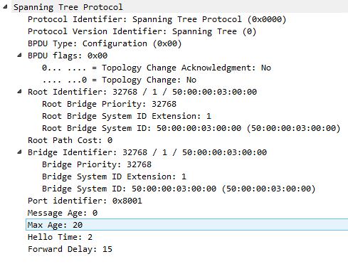
Thus, Switch2 receives the following BPDU from Switch3:

And Switch3 from Switch2 gets this BPDU:
After exchanging such BPDUs, Switch2 and Switch3 understand that the topology is redundant. Why do switches understand that topology is redundant? Both Switch2 and Switch3 in their BPDUs report the same Root Bridge. This means that there are two ways to Root Bridge, relative to Switch3, through Switch1 and Switch2, and this is the very redundancy we are fighting against. There are also two ways for Switch2 - via Switch1 and Switch3. To get rid of this redundancy
You must lock the channel between Switch3 and Switch2. How does this happen?
The choice of which switch to block the port is as follows:
- Smaller Root Path Cost.
- Smaller Bridge ID.
- Smaller port id.
In this scheme, the Root Path Cost plays a more important role than the Bridge ID. I used to think that this choice is similar to the choice of the Root switch and was surprised that, for example, in such a topology, the port on the switch with the worst priority would be blocked:
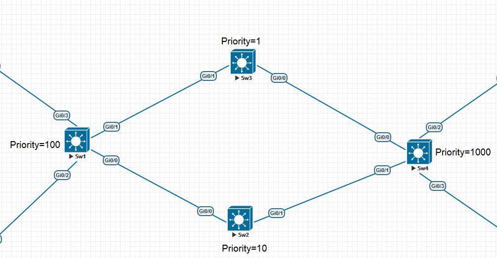
Here, as it turned out, the port Gi 0/1 is blocked on the switch Sw2. In this voting, Root Path Cost becomes decisive. Let's return to our topology. Since the path to the Root Bridge is the same, Switch2 wins in this choice, since its priority is equal, the Bridge ID is compared. At Switch2 - 50: 00: 00: 02: 00: 00, at Switch3 - 50: 00: 00: 03: 00: 00. Switch2 has a better (lower) MAC address. After the choice is made, Switch3 stops forwarding any packets through this port - Gi1 / 0, including BPDU, and only listens to BPDU from Switch2. This port state in STP is called Blocking (BLK). The Gi2 / 0 port on Switch2 works in the normal mode and forwards various packets if necessary, but Switch3 discards them immediately, listening only to BPDUs. Thus, in this example, we built a topology without redundant channels. The only redundant link between Switch2 and Switch3 was blocked by switching the port Gi1 / 0 on Switch3 to a special blocking state - BLK. Now we will analyze STP mechanisms in more detail.
Port states
We said above that, for example, the port Gi1 / 0 on Switch3 enters a special blocking state - Blocking. In STP, the following port states exist:
Blocking - blocking. In this state, no frames are transmitted through the port. Used to avoid redundancy topology.
Listening - listening. As we said above, before the root switch is selected yet, the ports are in a special state where only BPDUs are transmitted, data frames are not transmitted and are not accepted in this case. The Listening state does not enter the next even if the Root Bridge is defined. This port state lasts for the Forward delay timer, which, by default, is 15. Why do you always have to wait 15 seconds? This is due to the caution of the STP protocol so that an incorrect Root Bridge was not chosen by chance. After this period, the port enters the next state - Learning.
Learning - learning. In this state, the port listens and sends BPDUs, but does not send information with data. The difference between this state and Listening is that the frames with data that arrive at the port are studied and the information about MAC addresses is entered into the table of MAC addresses of the switch. The transition to the next state also takes Forward delay timer.
Forwarding - forwarding. This is the normal port state in which both BPDU packets and regular data frames are sent. Thus, if we go through the scheme when the switches are only loaded, we get the following scheme:
- The switch places all its connected ports in the Listening state and starts sending BPDUs, where it declares itself as the root switch. During this time period, either the switch remains the root, if it does not receive the best BPDU, or it selects the root switch. It lasts 15 seconds.
- After it goes to the Learning state and learns the MAC addresses. 15 seconds.
- Specifies which ports to transfer to the Forwarding state, and which in Blocking.
Port roles
In addition to the states of the ports, the STP also needs to determine the ports for their role. This is done so that on which port BPDUs should be expected from the root switch and through which ports to transmit copies of BPDUs received from the root switch. Port roles are as follows:
Root Port - the root port of the switch. When selecting the root switch, the root port is also determined. This is the port through which the root switch is connected. For example, in our topology, the Gi0 / 0 ports on Switch2 and Switch3 are the root ports. Through these ports, Switch2 and Switch3 do not send BPDUs, but only listen to them from the Root Bridge. The question arises - how is the root port selected? Why is the Gi1 / 0 port not selected? Do you also have a connection with the switch through it? To determine the root port in STP, a metric is used, which indicates the BPDU - Root Path Cost field (the cost of the route to the root switch). This cost is determined by the speed of the channel.
Switch1 in its BPDU in the field Root Path Cost puts 0, since it is the Root Bridge itself. But when Switch2, when sending BPDUs to Switch3, changes this field. He puts Root Path Cost equal to the cost of the channel between himself and Switch1. In the BPDU picture from Switch2 and Switch3, you can see that in this field, the Root Path Cost is 4, since the channel between Switch1 and Switch2 is 1 Gbps. If the number of switches is greater, then each next switch will summarize the cost of Root Path Cost. Table Root Path Cost.
Designated Port is the designated port of the segment. For each network segment there should be a port that is responsible for connecting this segment to the network. Relatively speaking, a network segment can mean a cable that connects this segment. For example, the Gi0 / 2 ports on Switch1, Switch3 connect individual network segments to which only this cable leads. Also, for example, the ports on the Root Bridge cannot be blocked and all are designated segment ports. After this explanation, more strict definitions can be given for the assigned ports:
Designated Port (assigned) - non-root port of the bridge between network segments, receiving traffic from the corresponding segment. In each network segment there can be only one assigned port. At the root switch all ports are assigned.
It is also important to note that the port Gi1 / 0 on Switch2 is also assigned, despite the fact that this communication channel is blocked on Switch3. Relatively speaking, Switch2 has no information that the port is blocked at the other end.
Nondesignated Port - unassigned port segment. Non-designated Port (unassigned) - a port that is not the root, or designated. Transmission of data frames through such a port is prohibited. In our example, the port Gi1 / 0 is unassigned.
Disabled Port - a port that is in the off state.
Timers and STP Convergence
After the STP has completed building a loop-free topology, the question remains - How to identify changes in the network and how to respond to them? BPDU messages with which STP is running are sent to the Root Bridge every 2 seconds, by default. This timer is called Hello Timer. The remaining switches receive this message through their root port and forward it through all designated ports. Above it is said in more detail what changes happen to the BPDU when forwarding its switches. If during the time specified by the Max Age timer (default is 20 seconds), the switch did not receive any BPDUs from the root switch, then this event is interpreted as a loss of communication with the Root Bridge. In order to more correctly describe the convergence of the protocol, it is necessary to change our topology and put hubs between switches. We added hubs so that when one of the switches fails or the link fails, the other switches do not detect this by dropping the link, but using timers:
Before you begin it is also important to talk more about another type of STP message - TCN. TCN is distributed by switches in the event of a topology change — as soon as a topology has changed on a switch, for example, the state of the interface has changed. The TCN is sent by the switch only through the Root Port. As soon as the root switch receives a TCN, it immediately changes the storage time parameter of MAC addresses in the table from 300 seconds to 15 (what it is done for below) and in the next BPDU, the Root Switch taps the flag - TCA (Topology Change Acknledgement), which sent to the switch that sent the TCN to indicate that the TCN was received. As soon as the TCN reaches the Root Bridge, it sends out a special BPDU that contains the TCN flag on all other interfaces to the other switches. The picture shows the structure of TCN:

TCN was included in the STP so that non-root switches can report a change in the network. They cannot do this with regular BPDUs, since non-root switches do not send BPDUs. As you can see, the TCN structure does not contain any information about what exactly has changed and where, but simply reports that something has changed somewhere. We now turn to the question of the convergence of STP.
Let's see what happens if we disable the Gi0 / 1 interface on Switch1 and see with what mechanisms the STP tree is rebuilt. Switch2 will stop receiving BPDUs from Switch1 and will not receive BPDUs from Switch3, since this port is blocked on Switch3. Switch2 will take 20 seconds (Max Age Timer) to understand the loss of communication with the Root Bridge. Until that time, Gi0 / 0 on Switch2 will be in the Forwarding state with the Root Port role. As soon as Max Age Timer expires and Switch2 understands the loss of communication, it will rebuild the STP tree and, as it is typical of STP, it will begin to consider itself Root Bridge. It will send a new BPDU, where it will point itself as the Root Bridge through all active ports, including Switch3. But the Max Age timer expired on Switch2 also expired on Switch3 for the Gi1 / 0 interface. This port has not received BPDU for 20 seconds and this port will switch to the LISTENING state and send BPDUs with the indication as Root Bridge - Switch1. As soon as Switch2 accepts this BPDU, it will no longer consider itself Root Bridge and will select Gi1 / 0 as Root Port. At this point, Switch2 will also send TCN via Gi1 / 0, since this is the new Root Port. This will cause the storage time of the MAC addresses on the switches to decrease from 300 seconds to 15. But this will not fully restore the network’s performance, you must wait until the Gi1 / 0 port on Switch3 passes the Listening state and then Learning. It will take time equal to two periods. Forward delay timer - 15 + 15 = 30 seconds. What we get is that when the connection is lost, Switch2 waits until the Max Age timer expires = 20 seconds, re-selects the Root Bridge via another interface and waits another 30 seconds while the previously blocked port switches to the Forwarding state. In total, the connection between VPC5 and VPC6 is interrupted for 50 seconds. As mentioned by several suggestions above, when the Root Port was changed from Gi0 / 0 to Gi1 / 0 to TC2, TCN was sent. If this did not happen, then all MAC addresses learned through the Gi 0/0 port would remain bound to Gi0 / 0. For example, the MAC address of VPC5 and VPC7, although the STP will complete convergence after 50 seconds, the connection between VPC6 and VPC5, VPC7 would not be restored, since all packets destined for VPC5, VPC7 were sent via Gi0 / 0. It would be necessary to wait not 50 seconds, but 300 seconds while the table of MAC addresses is rebuilt. With TCN, the storage time changed from 300 seconds to 15 and while the Gi1 / 0 interface on Switch3 passed the Listening state, and then the Learning and MAC address information is updated.
Also an interesting question is what happens if we re-enable the Gi0 / 1 interface on Switch1? When you enable the Gi0 / 1 interface, it will, as befits, switch to the Listening state and begin sending BPDUs. As soon as Switch2 receives BPDUs on Gi0 / 0, it will immediately re-select its Root Port, since here Cost will be the smallest and start sending traffic through Gi0 / 0 interface, but we need to wait until Gi0 / 1 interface passes Listening, Learning status to Forwarding . And the delay will not be 50 seconds, but 30.
The STP protocol also considers various technologies to optimize and secure the operation of the STP protocol. In more detail in this article I will not consider them, materials about them can be found in abundance on various sites.
Source: https://habr.com/ru/post/419491/
All Articles