Creating an emulator arcade machine. Part 4
Parts first , second , third .
The rest of the machine
The code we wrote to emulate an 8080 processor is quite general and can be easily adapted to run on any machine with the C compiler. But in order to play the game itself, we need to do more. We'll have to emulate the equipment of the entire arcade machine and write the code sticking the specific features of our computing environment to the emulator.
(It may be interesting for you to look at the schematic diagram of the machine.)
Timings
The game runs on a 2-MHz 8080. Your computer is much faster. To take this into account, we will have to come up with some mechanism.
')
Interruptions
Interrupts are designed to allow the processor to process tasks with precise execution times, such as I / O. The processor can execute the program, and when the interrupt pin is triggered, it stops executing the current program and does something else.
We need to simulate the way an arcade machine generates interrupts.
Graphics
Space Invaders draws graphics to its memory in the 0x2400 address range. A real hardware video controller would read RAM and control the CRT display. Our program will have to emulate this behavior by drawing a picture of the game in the window.
Buttons
The game has physical buttons that the program reads using the IN command of the 8080 processor. Our emulator will have to bind the IN input to these commands from the keyboard.
ROM and RAM
It is necessary to admit: we "cut off the corner" by creating a 16-kilobyte memory buffer, which includes the lower 16 KB of memory allocation of the processor. In fact, the first 2 KB of memory allocation are real ROM (ROM, read-only memory). We will need to put write operations in memory into a function so that it is impossible to write to ROM.
Sound
While we did not say anything about the sound. Space Invaders has a cute analog sound scheme that reproduces one of 8 sounds, controlled by the OUT command, which is transmitted to one of the ports. We will have to convert these OUT commands to play audio samples on our platform.
It may seem like a lot of work, but it's not so bad, and we can move gradually. The first thing we want to do is to see the screen, for which we will need interrupts, graphics, and part of the processing of IN and OUT commands.
Displays and updates
The basics
You probably know the components of a video display system. Somewhere in the system there is some kind of RAM that contains an image to display on the screen. In the case of analog devices, there is equipment that reads this RAM and converts bytes into analog voltage transmitted to a monitor.
A deeper understanding of the system will help us when it comes to analyzing the purpose of allocating memory and code functionality.
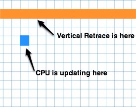
Analog displays have refresh rate and timing requirements. At any given time on the display is updated specific pixel. The image transmitted on the screen is filled point by point, starting from the top left corner and up to the top right, then the first point of the second line, the last point of the second line, etc. After the last line is drawn on the screen, the video controller can generate a Vertical Blank Interrupt (also known as VBI or VBL) interrupt.
To ensure smooth animation, the image in RAM processed by the video controller cannot be changed. If the update of RAM occurred in the middle of the frame, the viewer will see parts of the two images. This leads to the effect of "breaking", when a frame that is different from the frame at the bottom is shown at the top of the screen. If you've ever seen a line break, you know what it looks like.
To avoid breaks, the software must do something to avoid transferring the location of the screen update. And there is only one way to do this.
VBL is generated after the last line is completed, and usually there is a certain amount of time before the first line is drawn again. (This is the time of Vertical Blank, and it can be about 1 millisecond.)
When you receive a VBL program begins to draw the screen on top.
Each line is drawn before the process of reverse frame sweep.
The CPU is always in front of a reverse hotkey and therefore avoids breaking lines.
Space Invaders Video System
A very informative page tells us that Space Invaders has two video interruptions. One is for the end of the frame, but it also generates an interrupt in the middle of the screen. The page describes the screen update system — the game draws graphics in the upper half of the screen when it receives an interrupt from the middle of the screen, and draws graphics at the bottom of the screen when it receives an interruption from the end of the frame. This is a pretty smart way to eliminate line breaks, and a good example of what can be achieved when you develop hardware and software at the same time.
We have to force the emulation of our automaton to generate such interrupts. If we generate them with a frequency of 60 Hz, like the Space Invaders machine, then the game will be drawn with the correct frequency.
In the next section, we will talk about interrupt mechanics and think about how to emulate them.
Buttons and Ports
8080 implements I / O using IN and OUT instructions. It has 8 separate ports IN and OUT - the port is determined by the command data byte. For example,
IN 3 will put port 3 in register A, and OUT 2 will send A to port 2.I took the information about the purpose of each port from the Computer Archeology website. If this information were not available, we would have to get it by studying the concept, as well as by reading and step-by-step code execution.
:
1
0 (0, )
1 Start
2 Start
3 ?
4
5
6
7 ?

2
0,1 DIP- (0:3,1:4,2:5,3:6)
2 ""
3 DIP- , 1:1000,0:1500
4
5
6
7 DIP-, 1:,0:

3

2 ( 0,1,2)
3
4
5
6 "" ? , ,
(0=a,1=b,2=c ..)

( 3,5,6 1=$01 2=$00
, (attract mode))
There are three ways to implement I / O in our software stack (which consists of an 8080 emulator, machine code and platform code).
- Embed knowledge about the machine in our 8080 emulator
- Embed the knowledge of the 8080 emulator in the code of the machine
- Invent a formal interface between the three parts of the code to enable the exchange of information through the API
I excluded the first option - it is fairly obvious that the emulator is at the very bottom of this call chain and should remain separate. (Imagine that you need to re-use the emulator for another game, and you will understand what I mean.) In general, transferring high-level data structures to lower levels is a poor architectural solution.
I chose option 2. Let me first show the code:
while (!done) { uint8_t opcode = state->memory[state->pc]; if (*opcode == 0xdb) //machine specific handling for IN { uint8_t port = opcode[1]; state->a = MachineIN(state, port); state->pc++; } else if (*opcode == 0xd3) //OUT { uint8_t port = opcode[1]; MachineOUT(state, port); state->pc++; } else Emulate8080Op(state); } This code re-implements the processing of opcodes for IN and OUT in the same layer that causes the emulator for the remaining commands. In my opinion, this allows you to make the code cleaner. This is similar to a redefinition or subclass for these two commands, which belongs to the automaton layer.
The disadvantage is that we transfer the opcode emulation in two places. I will not blame you for choosing the third option. In the second variant, less code is required, but option 3 is more “clean”, however the price is an increase in complexity. This is a matter of style choice.
Shift register
The slot machine Space Invaders has an interesting hardware solution that implements the bit shift command. The 8080 has commands to shift by 1 bit, but to implement a multi-bit / multi-byte shift, you will need dozens of 8080 commands. Special hardware allows the game to perform these operations in just a few instructions. It draws every frame on the game field, that is, it is used many times per frame.
I don’t think I can explain it better than Computer Archeology’s excellent analysis :
; 16- :
; f 0
; xxxxxxxxyyyyyyyy
;
; 4 x y, x, :
; $0000,
; write $aa -> $aa00,
; write $ff -> $ffaa,
; write $12 -> $12ff, ..
;
; 2 ( 0,1,2) 8- , :
; offset 0:
; rrrrrrrr result=xxxxxxxx
; xxxxxxxxyyyyyyyy
;
; offset 2:
; rrrrrrrr result=xxxxxxyy
; xxxxxxxxyyyyyyyy
;
; offset 7:
; rrrrrrrr result=xyyyyyyy
; xxxxxxxxyyyyyyyy
;
; 3 .
For the OUT command, the entry in port 2 sets the offset value, and the entry in port 4 sets the data in the shift registers. Reading with IN 3 returns data shifted by the amount of shift. In my machine, it is implemented like this:
-(uint8_t) MachineIN(uint8_t port) { uint8_t a; switch(port) { case 3: { uint16_t v = (shift1<<8) | shift0; a = ((v >> (8-shift_offset)) & 0xff); } break; } return a; } -(void) MachineOUT(uint8_t port, uint8_t value) { switch(port) { case 2: shift_offset = value & 0x7; break; case 4: shift0 = shift1; shift1 = value; break; } } Keyboard
To get the automaton's response, we need to bind keyboard input to it. Most platforms have a way to get keystroke and release events. The platform code for the buttons will look like the following:
if(PeekMessage(&msg,NULL,0,0,PM_REMOVE)) { if (msg.message==WM_KEYDOWN ) { if ( msg.wParam == VK_LEFT ) MachineKeyDown(LEFT); } else if (msg.message==WM_KEYUP ) { if ( msg.wParam == VK_LEFT ) MachineKeyUp(LEFT); } } The automat code sticking the platform code to the emulator code will look something like this:
MachineKeyDown(char key) { switch(key) { case LEFT: port[1] |= 0x20; //Set bit 5 of port 1 break; case RIGHT: port[1] |= 0x40; //Set bit 6 of port 1 break; /*....*/ } } PlatformKeyUp(char key) { switch(key) { case LEFT: port[1] &= 0xDF //Clear bit 5 of port 1 break; case RIGHT: port[1] &= 0xBF //Clear bit 6 of port 1 break; /*....*/ } } If you wish, you can arbitrarily combine the code of the machine and the platform - this is the choice of implementation. I will not do this, because I'm going to port the machine to several different platforms.
Interruptions
Having studied the directory, I realized that 8080 handles interrupts as follows:
- The interrupt source (external to the CPU) sets the pin of the interrupt to the CPU.
- When the CPU confirms the interrupt reception, the interrupt source can send any opcode to the bus and the CPU will see it. (Most often they use the RST command.)
- The CPU executes this command. If it is RST, then it is analogous to the CALL command for a fixed address at the bottom of the memory. She writes the current PC to the stack.
- The code in the lower memory address handles what the interrupt wants to tell the program. After processing is completed, RST ends with a call to RET.
The video equipment of the game generates two interrupts that we must emulate programmatically: the end of the frame and the middle of the frame. Both are performed at 60 Hz (60 times per second). 1/60 of a second is 16.6667 milliseconds.
To simplify working with interrupts, I will add a function to the 8080 emulator:
void GenerateInterrupt(State8080* state, int interrupt_num) { //perform "PUSH PC" Push(state, (state->pc & 0xFF00) >> 8, (state->pc & 0xff)); //Set the PC to the low memory vector. //This is identical to an "RST interrupt_num" instruction. state->pc = 8 * interrupt_num; } The platform code must implement a timer that we can call (for now, I'll just call it time ()). The machine code will use it to transmit an interrupt to the 8080 emulator. In the automaton code, when the timer expires, I will call GenerateInterrupt:
while (!done) { Emulate8080Op(state); if ( time() - lastInterrupt > 1.0/60.0) //1/60 second has elapsed { //only do an interrupt if they are enabled if (state->int_enable) { GenerateInterrupt(state, 2); //interrupt 2 //Save the time we did this lastInterrupt = time(); } } } There are some details of how the 8080 actually handles interrupts, which we will not emulate. I believe that such processing will be enough for our purposes.
Source: https://habr.com/ru/post/419143/
All Articles