Excursion to the substation 220/110/20
Before electricity from the power plant comes to our outlet, its voltage is first increased to hundreds of thousands of volts, and then lowered back to 220V. Do such transformations on transformer substations.
The most important characteristic of the substation is the voltage levels on the upper and lower sides. What is written in the title just means that there are 220 thousand volts on the upper side and two voltage levels of 110 and 20 kV on the lower side. That is, in fact, these are two substations in the same territory. And in our outlet according to the classification of energists 0.4kV, this is because. that between the phases of 400 volts (it used to be 380 but the standards have changed a long time ago).
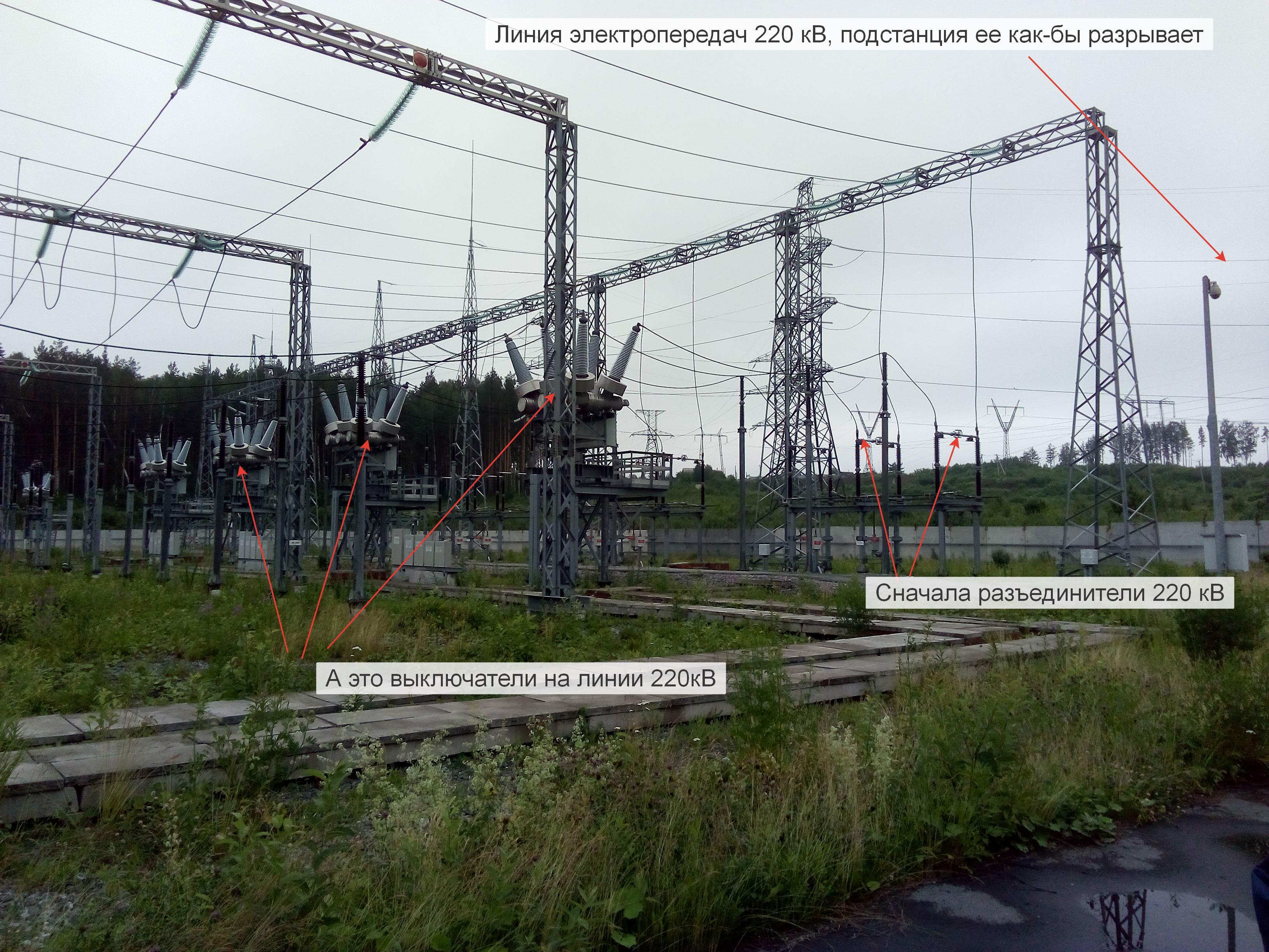
The substation beginswith an open switchgear with a safety briefing, then we go to the upper side of the substation to the open switchgear - the switchyard.
')
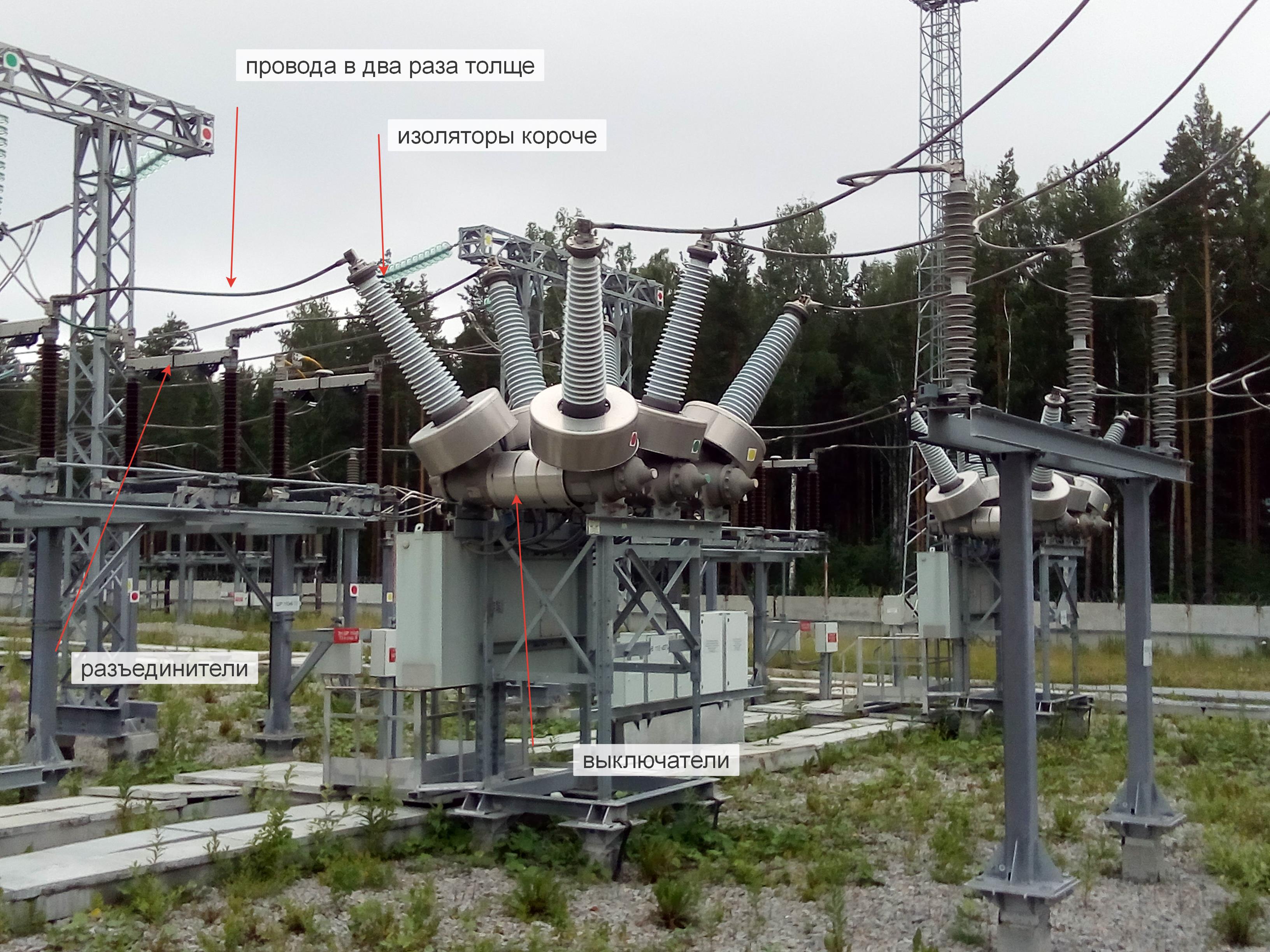
In general terms, power lines, disconnectors, gas-insulated switches, and portals with bus sections are visible.
Portals are metal structures over the entire visible farm, and the bus section refers to a part of the substation scheme that can be switched off by switches and disconnectors from the rest of the scheme. This substation can be powered from either end of the power line, and can also disconnect the line. I don’t know about this power line, but unlike the power cord of your PC, in which current always comes from the outlet, high-voltage power lines are for the most part included in a single power system and energy along such lines can flow from different sources (located from different sides of the line) to different consumers at different times. To do this, all the generators included in a single network work strictly synchronously.
Switching line 220 kV are gas-insulated circuit breakers.

Sulfur hexafluoride or hexafluoride is pumped into switches to better extinguish the arc when the contacts are disconnected. Everyone noticed a spark in the switch of the house or in the outlet when the plug was turned off - this is the same principle, but many orders of magnitude more. There are vacuum, oil switches, but the most reliable for today for such a voltage level is considered to be gas-insulated.
In the photo I showed a pressure gauge, it can be seen from the ground so that the worker could diagnose a gas leak. This model of the switch with gas leaked can not be turned off under load - it will collapse.
Also at the Russian substations there are necessarily disconnectors:
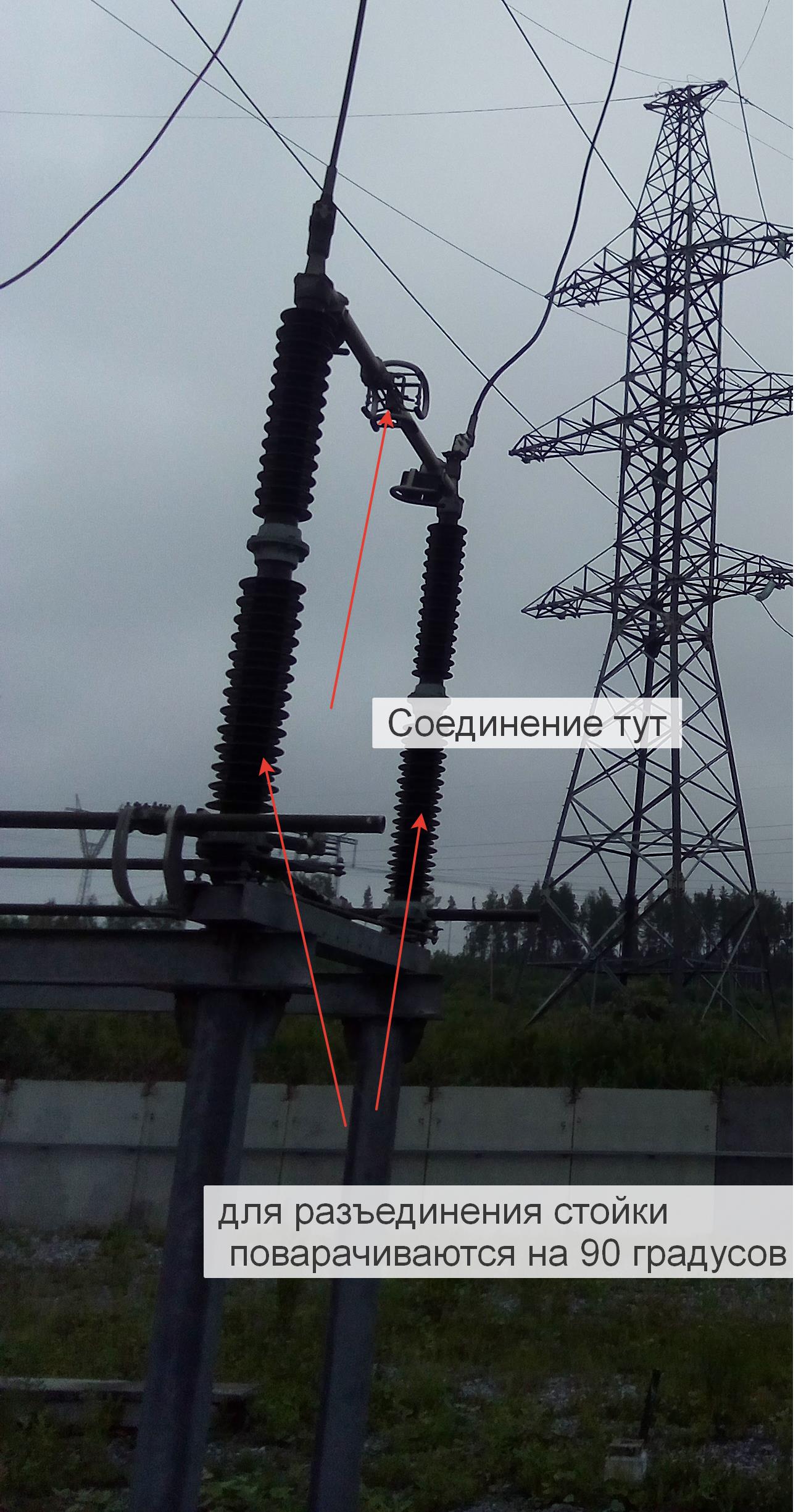
In fact, this is also a switch, but fully open; the disconnector can only be switched off without load. It is needed to create a “Visible physical gap” - this is a prerequisite for the safe execution of work at the substation facilities. That is, it is not enough to disconnect the gas-insulated switch and ground it, you need to see the physical gap.
Switches and disconnectors can be controlled both from the substation control panel and manually using special handles.
One of the devices interesting for the electronics engineer: high-frequency layer


Essentially, a coil and a capacitor make up an LC — a filter that does not allow a high-frequency signal into the network. And the high-frequency signal comes from another substation or power station, its frequency is around 40 kHz, and is used to transmit information, mainly the protection and automation systems. The transmission speed is very low, but the reliability of the method itself has proven itself for decades, and this type of communication is indispensable when building such objects. The signal power is of the order of 1kV and it is very difficult to technically distort or drown it.
It is impossible to measure directly the currents and voltages in such networks with devices, therefore, transformers are used for the operation of automation and measurements. The current transformer we saw in the picture with the gas-insulated switch, and the voltage transformers look like this:
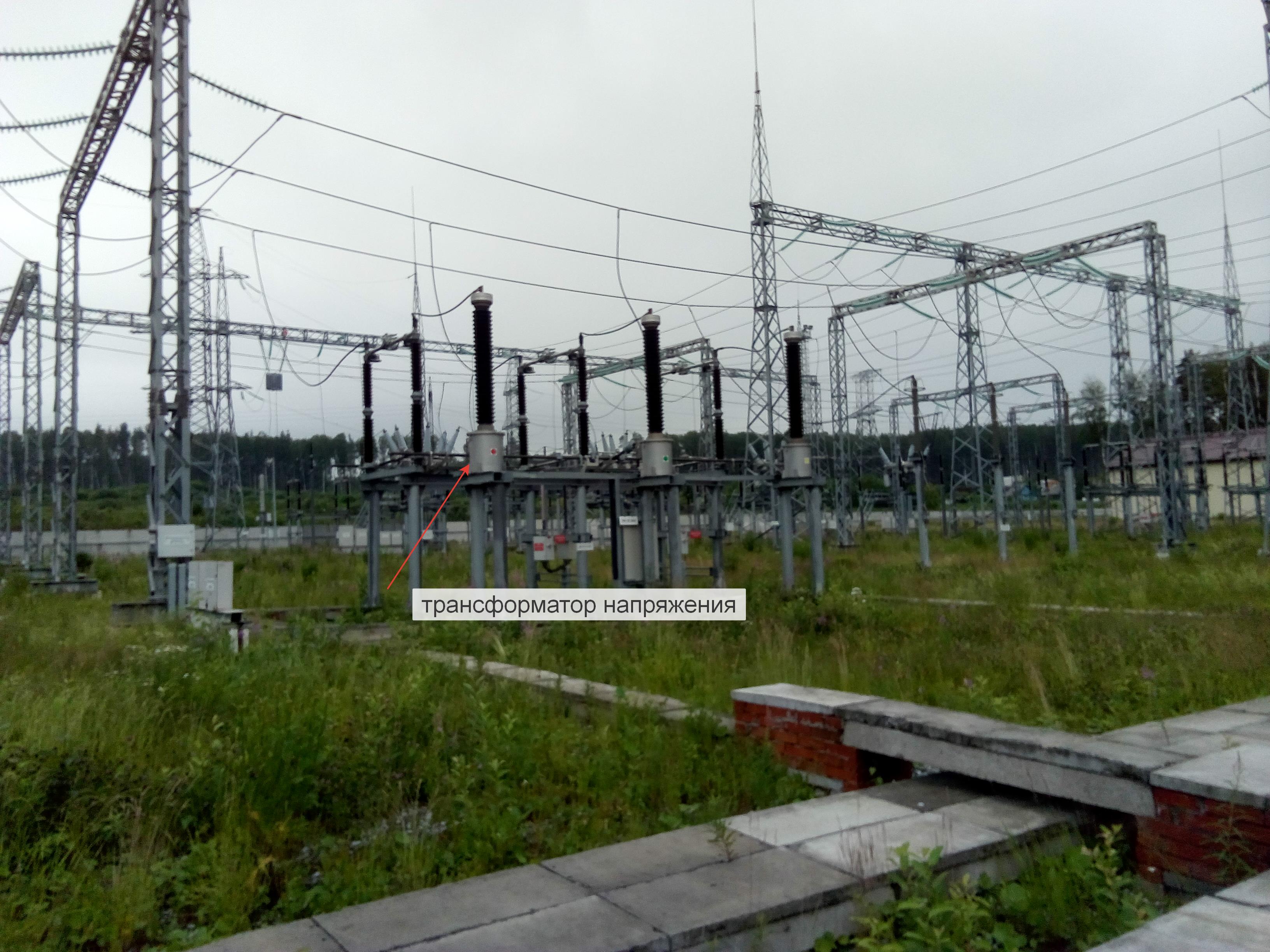
After the conversion, we get a maximum of 100 volts or 5 amps - all panel-mounted measuring devices and relay protection devices (relay protection and automation) are set to these values. In contrast to the standard industrial controllers: 1-10V and 4-20mA, levels of 100V and 5A are much more resistant to interference.
Another device on the upper side is overvoltage protection:

When lightning strikes, the resistance of the varistor drops sharply and dumps excess energy into the ground. And yes, it works on 190kV, because in a 220kV transmission line, each phase has a potential of less than 190kV relative to the ground.
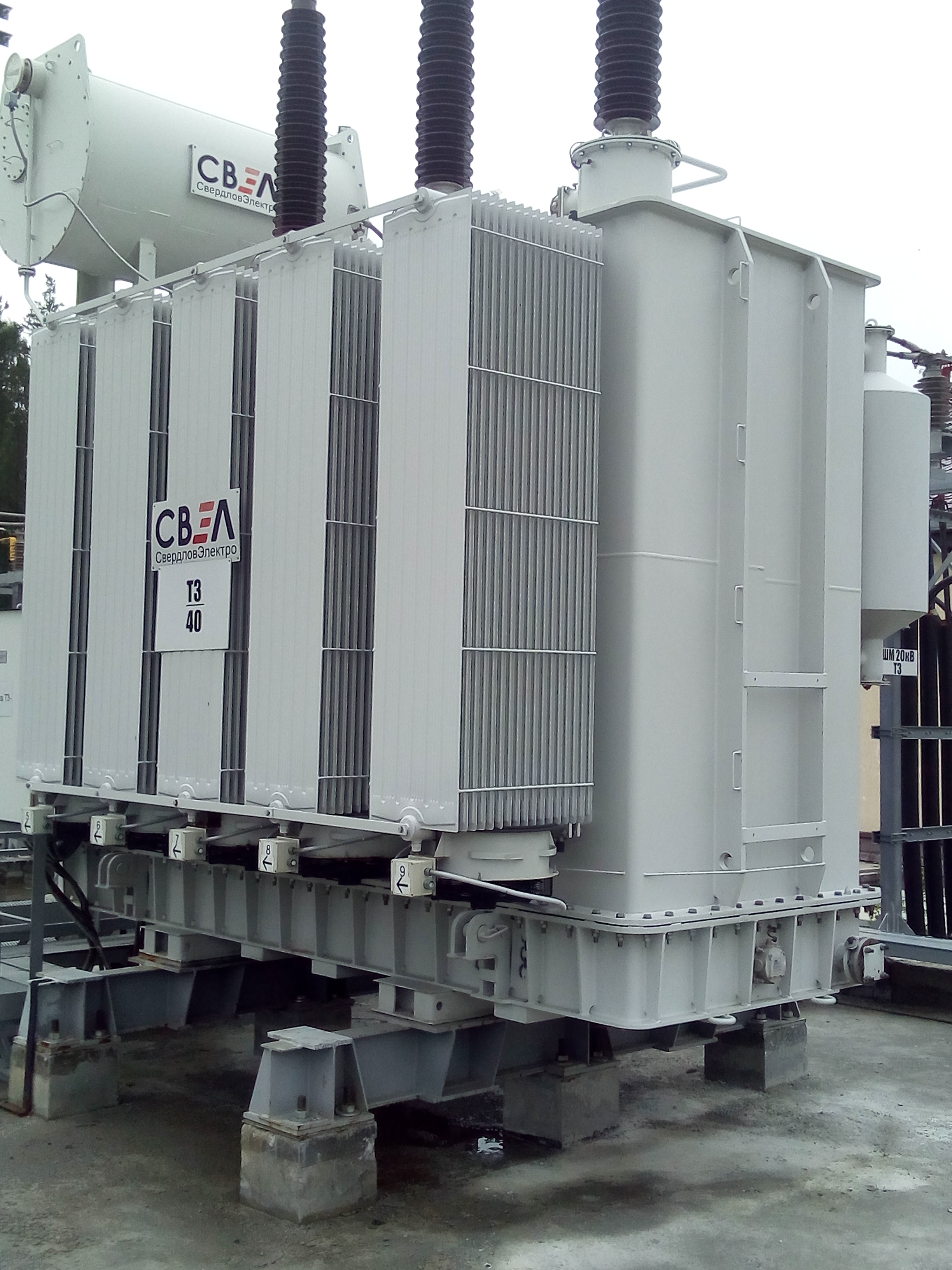
And here is the heart of the substation - the autotransformer 250 MVA (megavoltamper):
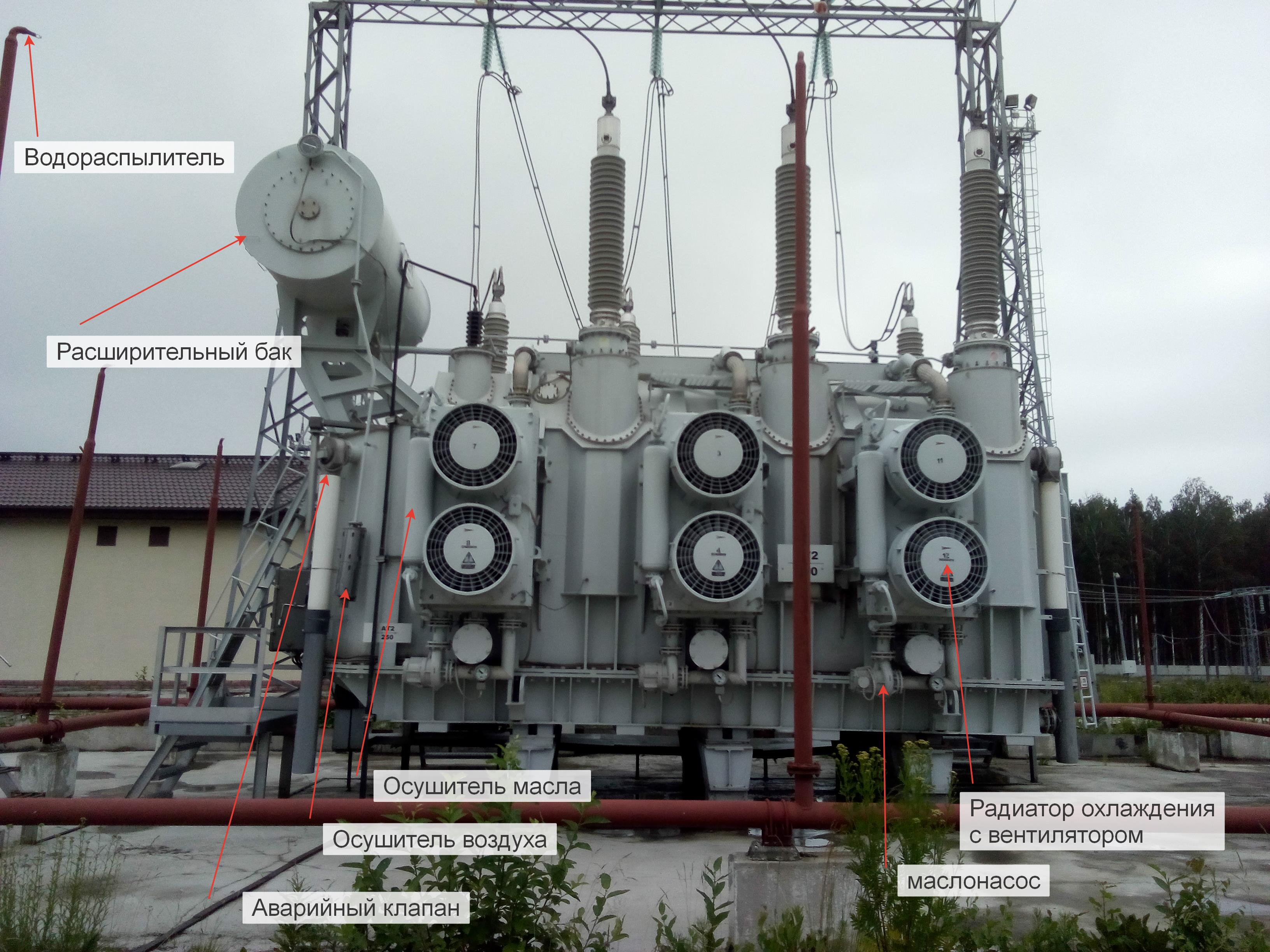
The transformer has many devices to ensure its operation and protection. In the event of a fire, it is extinguished with water, although the oil is not extinguished with water, but if there is no money for the fishery, you really want the water. A system of sprayers is used, during operation of which a cloud of steam and water is formed around the transformer, which blocks the access of oxygen and the fire stops.
It is called an autotransformer because it has a connection between the primary and secondary windings as in LATR - and it is considered that its efficiency is higher than that of a classical transformer.
This transformer has two secondary windings 110 and 10. A 10 kV winding is used only for its own needs. As practice has shown, if we load a 10Kw winding at a nominal value, non-envisaged electromagnetic fields are formed and the bolts with which the transformer bottom is bolted start to glow.
The load on the network is not constant and this transformer also provides voltage control for the load.

The handle can be twisted only during repair and adjustment, during working hours - only the electric drive and automatic equipment.
On the entire high side (by the way, it is called high by the voltage level, physically everything is in the same plane), the crackling of the discharges is constantly heard and it tires us pretty quickly.
After the autotransformer begins the low side with a voltage level of 110
Here, everything is the same: open switchgear, switches, portals, bus sections ...
Voltage transformers:

Disconnectors and switches:
And electricity is sent to other substations.
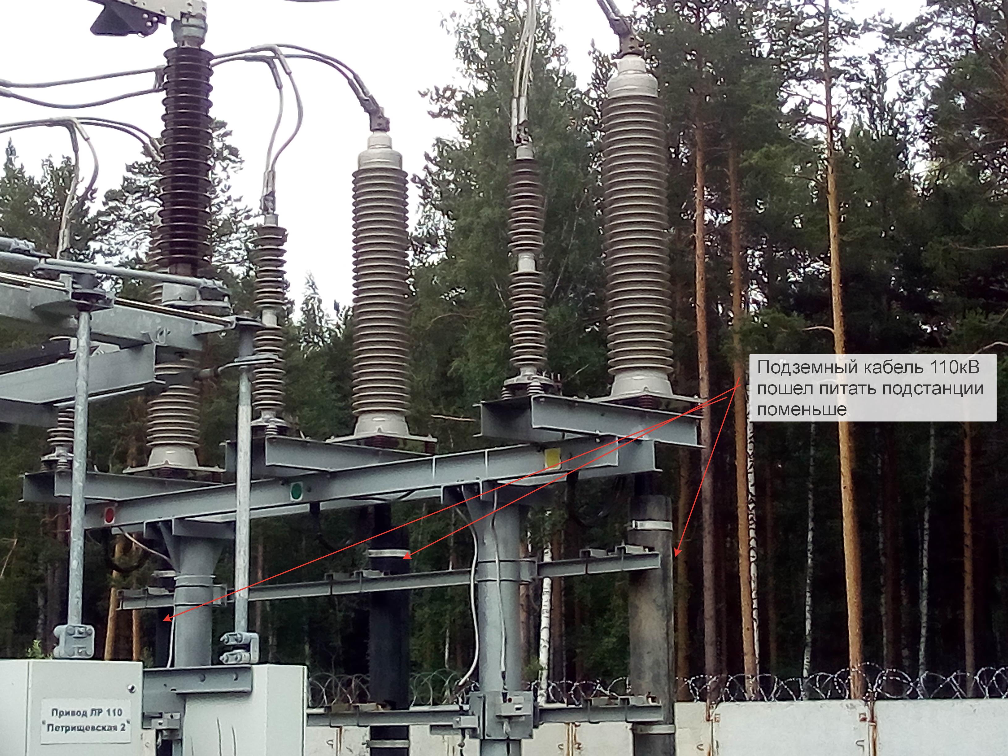
But there is also a second low side, begins after a 110/20 transformer.
The transformer is smaller, the cooling system is passive, this is already a classic transformer, not an autotransformer. But all the systems of oil and air drainage, protection are also present. On the side of 110 silence, cod discharges not at all.
The lowest side of the substation is 20kV. presented to indoor switchgear - closed distribution device

If the 220 kV outdoor switchgear closer than 4 meters to the live parts is prohibited to approach, then in the 20 kV indoor switchgear you can safely touch the equipment

Everything is closed, marked, controlled from the remote control or manually, it is impossible to open the cell just like that - everything is blocked by automation.
For repair, the cells roll out on such carts:
For control and management are used domestic controllers:
Further, the voltage of 20kV enters the local substation via underground cables. Networks with voltage above 0.4kV are isolated from the ground (well, not quite 100% but there is no usual zero in such networks). During the breakdown to earth, the current still flows, but is perceived as normal consumption, and the arc at the same time damages the insulation of the cable and ultimately leads to its damage and interfacial closure. To prevent this, a special system was invented:
A transformer with a midpoint is placed on the three phases of the cable, and when the load on the phases is equal, the voltage at the midpoint relative to the earth is equal to zero, and when closed to earth, the voltage increases and is an indicator of a problem. To determine the specific cable. in which the closure occurred use large resistors.
There are also arc-suppressing coils, which allow to compensate for the potential difference, to extinguish the arc, and according to the stories insulation is sometimes delayed and cable repair is not required.

Main station substation:
on the cabinets there is a diagram of the substation and the controls are inscribed in the diagram - before entering, it was strictly reminded that no pens were twisted and nothing was pressed. Behind the console are a bunch of cabinets with AC and DC power systems (all protection operates on a fully autonomous DC network), alarm systems, fire extinguishing systems, etc. All closed.
This is what a high-frequency communication device looks like, the very thing that is connected to a high-frequency interceptor and communicates with its counterparts in other substations.
In conclusion, we were allowed into the telemetry and RZA hall: I was waiting for something interesting, but the hall was filled with closed cabinets with incomprehensible abbreviations. There was no time left and it was not possible to question the details.
Here is one of the cabinets, where something is visible:

In the photo, universal level converters that convert 100V 5A to 24V 20mA
Part of the relay protection is assembled on mechanical relays, part on logic controllers. All information is displayed on the dispatcher's workplace on a PC screen, from where it can be controlled. Also, all information arrives at the central control center of the network organization.
At this, our tour ended, we gave up our helmets, and once again looking at the switchgear, we left the territory, accompanied by security.
From the point of view of me as an IT person, the approaches to protection, blocking, management, control are organized at the highest, one might say “iron” level - it is quite possible to borrow when building information systems.
The most important characteristic of the substation is the voltage levels on the upper and lower sides. What is written in the title just means that there are 220 thousand volts on the upper side and two voltage levels of 110 and 20 kV on the lower side. That is, in fact, these are two substations in the same territory. And in our outlet according to the classification of energists 0.4kV, this is because. that between the phases of 400 volts (it used to be 380 but the standards have changed a long time ago).
The substation begins
')
In general terms, power lines, disconnectors, gas-insulated switches, and portals with bus sections are visible.
Portals are metal structures over the entire visible farm, and the bus section refers to a part of the substation scheme that can be switched off by switches and disconnectors from the rest of the scheme. This substation can be powered from either end of the power line, and can also disconnect the line. I don’t know about this power line, but unlike the power cord of your PC, in which current always comes from the outlet, high-voltage power lines are for the most part included in a single power system and energy along such lines can flow from different sources (located from different sides of the line) to different consumers at different times. To do this, all the generators included in a single network work strictly synchronously.
Switching line 220 kV are gas-insulated circuit breakers.
Sulfur hexafluoride or hexafluoride is pumped into switches to better extinguish the arc when the contacts are disconnected. Everyone noticed a spark in the switch of the house or in the outlet when the plug was turned off - this is the same principle, but many orders of magnitude more. There are vacuum, oil switches, but the most reliable for today for such a voltage level is considered to be gas-insulated.
In the photo I showed a pressure gauge, it can be seen from the ground so that the worker could diagnose a gas leak. This model of the switch with gas leaked can not be turned off under load - it will collapse.
Also at the Russian substations there are necessarily disconnectors:
In fact, this is also a switch, but fully open; the disconnector can only be switched off without load. It is needed to create a “Visible physical gap” - this is a prerequisite for the safe execution of work at the substation facilities. That is, it is not enough to disconnect the gas-insulated switch and ground it, you need to see the physical gap.
Switches and disconnectors can be controlled both from the substation control panel and manually using special handles.
One of the devices interesting for the electronics engineer: high-frequency layer
Essentially, a coil and a capacitor make up an LC — a filter that does not allow a high-frequency signal into the network. And the high-frequency signal comes from another substation or power station, its frequency is around 40 kHz, and is used to transmit information, mainly the protection and automation systems. The transmission speed is very low, but the reliability of the method itself has proven itself for decades, and this type of communication is indispensable when building such objects. The signal power is of the order of 1kV and it is very difficult to technically distort or drown it.
It is impossible to measure directly the currents and voltages in such networks with devices, therefore, transformers are used for the operation of automation and measurements. The current transformer we saw in the picture with the gas-insulated switch, and the voltage transformers look like this:
After the conversion, we get a maximum of 100 volts or 5 amps - all panel-mounted measuring devices and relay protection devices (relay protection and automation) are set to these values. In contrast to the standard industrial controllers: 1-10V and 4-20mA, levels of 100V and 5A are much more resistant to interference.
Another device on the upper side is overvoltage protection:
When lightning strikes, the resistance of the varistor drops sharply and dumps excess energy into the ground. And yes, it works on 190kV, because in a 220kV transmission line, each phase has a potential of less than 190kV relative to the ground.
And here is the heart of the substation - the autotransformer 250 MVA (megavoltamper):
The transformer has many devices to ensure its operation and protection. In the event of a fire, it is extinguished with water, although the oil is not extinguished with water, but if there is no money for the fishery, you really want the water. A system of sprayers is used, during operation of which a cloud of steam and water is formed around the transformer, which blocks the access of oxygen and the fire stops.
It is called an autotransformer because it has a connection between the primary and secondary windings as in LATR - and it is considered that its efficiency is higher than that of a classical transformer.
This transformer has two secondary windings 110 and 10. A 10 kV winding is used only for its own needs. As practice has shown, if we load a 10Kw winding at a nominal value, non-envisaged electromagnetic fields are formed and the bolts with which the transformer bottom is bolted start to glow.
The load on the network is not constant and this transformer also provides voltage control for the load.
The handle can be twisted only during repair and adjustment, during working hours - only the electric drive and automatic equipment.
On the entire high side (by the way, it is called high by the voltage level, physically everything is in the same plane), the crackling of the discharges is constantly heard and it tires us pretty quickly.
After the autotransformer begins the low side with a voltage level of 110
Here, everything is the same: open switchgear, switches, portals, bus sections ...
Voltage transformers:
Disconnectors and switches:
And electricity is sent to other substations.
But there is also a second low side, begins after a 110/20 transformer.
The transformer is smaller, the cooling system is passive, this is already a classic transformer, not an autotransformer. But all the systems of oil and air drainage, protection are also present. On the side of 110 silence, cod discharges not at all.
The lowest side of the substation is 20kV. presented to indoor switchgear - closed distribution device
If the 220 kV outdoor switchgear closer than 4 meters to the live parts is prohibited to approach, then in the 20 kV indoor switchgear you can safely touch the equipment
Everything is closed, marked, controlled from the remote control or manually, it is impossible to open the cell just like that - everything is blocked by automation.
For repair, the cells roll out on such carts:
For control and management are used domestic controllers:
Further, the voltage of 20kV enters the local substation via underground cables. Networks with voltage above 0.4kV are isolated from the ground (well, not quite 100% but there is no usual zero in such networks). During the breakdown to earth, the current still flows, but is perceived as normal consumption, and the arc at the same time damages the insulation of the cable and ultimately leads to its damage and interfacial closure. To prevent this, a special system was invented:
A transformer with a midpoint is placed on the three phases of the cable, and when the load on the phases is equal, the voltage at the midpoint relative to the earth is equal to zero, and when closed to earth, the voltage increases and is an indicator of a problem. To determine the specific cable. in which the closure occurred use large resistors.
There are also arc-suppressing coils, which allow to compensate for the potential difference, to extinguish the arc, and according to the stories insulation is sometimes delayed and cable repair is not required.
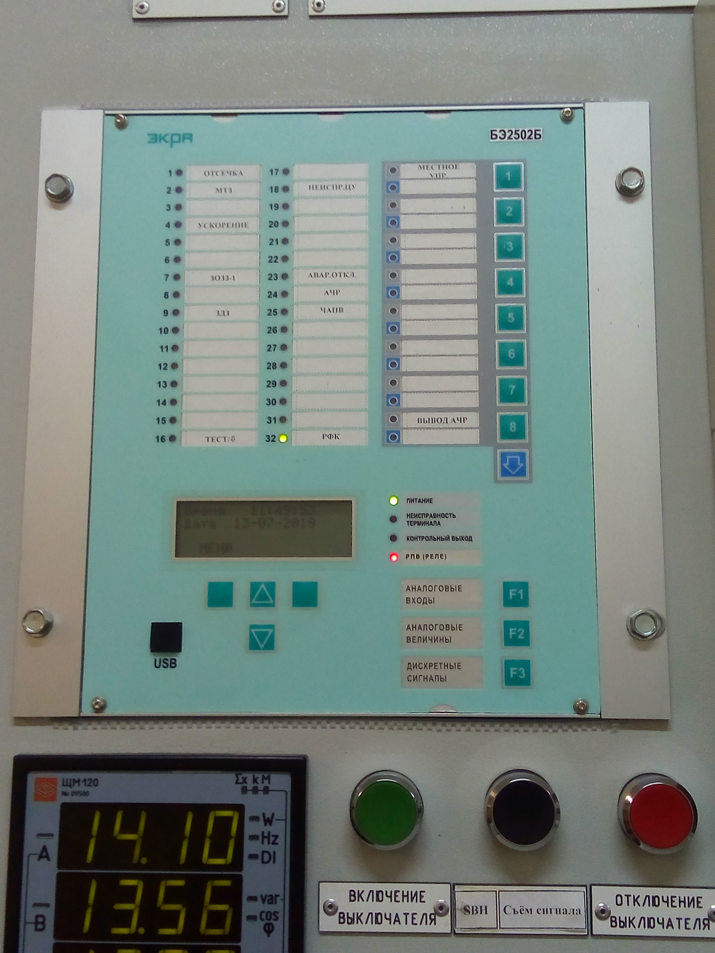
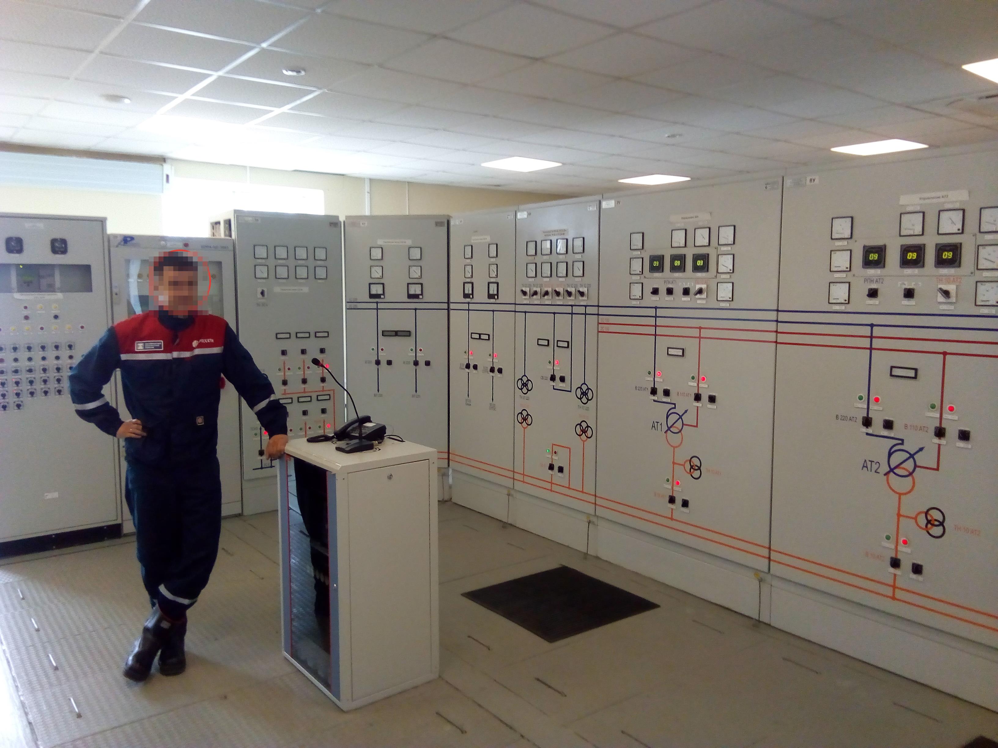
Main station substation:
on the cabinets there is a diagram of the substation and the controls are inscribed in the diagram - before entering, it was strictly reminded that no pens were twisted and nothing was pressed. Behind the console are a bunch of cabinets with AC and DC power systems (all protection operates on a fully autonomous DC network), alarm systems, fire extinguishing systems, etc. All closed.
This is what a high-frequency communication device looks like, the very thing that is connected to a high-frequency interceptor and communicates with its counterparts in other substations.
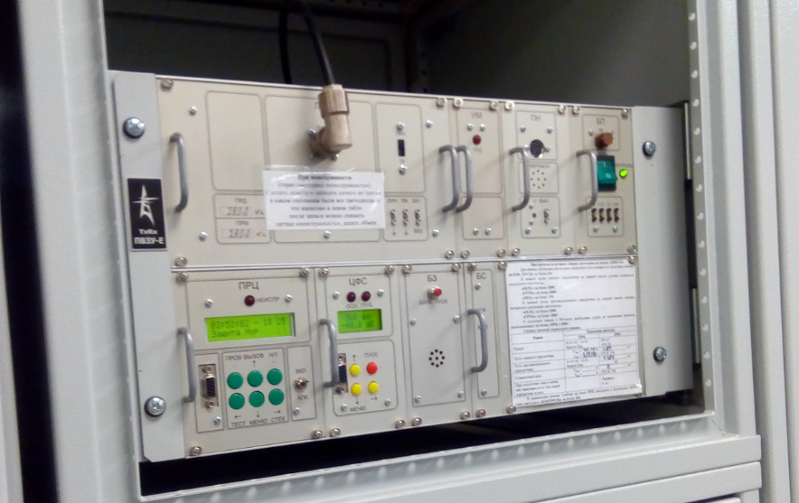
In conclusion, we were allowed into the telemetry and RZA hall: I was waiting for something interesting, but the hall was filled with closed cabinets with incomprehensible abbreviations. There was no time left and it was not possible to question the details.
Here is one of the cabinets, where something is visible:
In the photo, universal level converters that convert 100V 5A to 24V 20mA
Part of the relay protection is assembled on mechanical relays, part on logic controllers. All information is displayed on the dispatcher's workplace on a PC screen, from where it can be controlled. Also, all information arrives at the central control center of the network organization.
At this, our tour ended, we gave up our helmets, and once again looking at the switchgear, we left the territory, accompanied by security.
From the point of view of me as an IT person, the approaches to protection, blocking, management, control are organized at the highest, one might say “iron” level - it is quite possible to borrow when building information systems.
Source: https://habr.com/ru/post/419005/
All Articles