How to compress bootloader for STM8 to size 8 bytes in flash memory
Since the previous article, “How to compress a bootloader for STM8 to 18 bytes in FLASH memory,” there are two versions of the STM8uLoader bootloader. Loader STM8uLoader version $ 36 has learned to transfer control of the application program to any address in the RAM memory without the participation of the host program. The size of 18 bytes of the loader in FLASH memory has not changed, in the OPTION Bytes area the size has increased to 53 bytes (it took up all the available space).
The version of the $ 0D bootloader has been allocated to a separate branch. The main requirement for this version is to compress the code as much as possible. To date, the code size in FLASH memory is 8 bytes in the EEPROM memory is 35 bytes.
Let me remind the architecture of the STM8uLoader bootloader. The loader consists of the boot_PC program host and the boot_uC code in the STM8 memory. The latter is divided into the boot copier's boot_FLASH code in FLASH memory and the boot_EEPROM (or boot_OPTION) code in the EEPROM (or OPTION Bytes).
After the RESET event, the boot copier boot_FLASH is started, transfers the boot_EEPROM (or boot_OPTION) code image of the boot loader to the RAM and transfers control to it. The bootloader configures the UART transfers the host program a byte with its version number and, if it does not receive information from the program host during the timeout, transfers control to the application program in the FLASH memory. Either it transfers the code of the application program from the EEPROM memory (or the OPTION Bytes area) to the RAM memory and transfers control to it.
')
If, after the host program sends a byte with the version number, the bootloader receives a code dump via UART, it places it in the RAM memory and transfers control. The received code dump performs its current task: reading / copying / erasing / writing STM8 cells, transferring control to a specified address with preliminary initialization of the STM8 core registers, transferring control to the initial loader to change the current dump in the RAM memory by the host program.
The initial copyist boot_FLASH rev. $ 0D is located at $ 8000 ... $ 8007 and fully occupies the RESET and TRAP (Software interrupt) vectors. The rest of the space is $ 8008 ... $ 9FFF of FLASH memory is fully accessible to the application program. The interrupt vector table is also in place.
Consider the copyist code:
The code of two commands intersects here: the ldw X command, # $ 4088 (ldw X, # $ 4188) and the push A commands. The first time the loop is entered, the ldw X command, # $ 4088 (ldw X, # $ 4188) is executed, and the push A command is not executed . This solution saved one byte, but led to a narrowing of the table storage area with an image of the initial loader code. The low byte of the $ 88 table address does not allow placing it in the OPTION Bytes area. For the STM8S103F3 model, only the addresses $ 4088 and $ 4188 in the EEPROM memory are available to accommodate the specified table. For owners of STM8S003F3 with EEPROM memory of 128 bytes ($ 4000 ... $ 407F) and these addresses are not available. For them, there is still a loophole.
You only need to swap the push A and decw X commands:
Here, when first entering the loop, the ldw X command, # $ 405A ($ 415A, $ 425A) is executed, and the decw X command is not executed.
Recall that in the RESET event, the SP pointer to the top of the stack is hardware initialized to $ 03FF. The stack grows in the direction of decreasing addresses. To fill the stack from the tail, the table with the bootloader code will also be read from the tail, hence the decw X command. The image of the bootloader code is appropriately located in the EEPROM memory.
To save the abandoned cycle counter. We agreed that the image of the bootloader code will have a zero byte only at the beginning of the table, and the control transfer address of the application program (which may have a zero byte) will be moved out of the table. At each iteration, we read a byte from the table, and if it is not zero, push it onto the stack. The read zero byte is a condition for exiting the loop.
The ret command here means to transfer control to the address that is contained in the two bytes that were last hit on the stack. Consider now the bootloader code:
The brackets show the code addresses after copying to the stack. The first is the zero byte, in memory RAM is not copied. Next comes the control transfer address to the initial loader, in fact, this is the address of the next cell in the RAM memory. This pair is put onto the stack, but then overwritten as unnecessary by the code of the next dump from the host program. All subsequent code is also copied to the stack, except for a pair with the address of control transfer to the application program.
Next comes the UART initialization. Here in all three registers fit the same number $ 0D. In the first case, this is the UART speed (16000000/8/9600/16 = 13). In the second case, this is the transmission / reception resolution, here the locomotive caught the one-time generation of the BREAK event. In the latter case, this is sending the loader version to the host program. In fact, the host program will receive two bytes of $ 00 (BREAK event) and $ 0D (bootloader version number) - this is a signal that you can send a dump with a code.
Register A with the contents of $ 0D then serves as a counter of received bytes and counts them with an increment to zero, which is equivalent to 243 received bytes. It is with this size that the host program must send dumps with code.
The index register X in the initial copier counted to $ 4,068. Now, with an increment, it will also count to zero (there are still 49048 left) counting the time allotted for the work to the initial loader. During this time, the initial loader must have time to accept a dump with a code of 243 bytes in order to push it further onto the stack and transfer control to it. Otherwise, control will be transferred to the application program and you will have to press the reset button again and restart the host program.
After transferring control to the received dump, the boot loader code remains on the stack and re-takes control when the host program decides to replace the dump with the code. Any accepted code dump is located on the stack at $ 02ED ... $ 03DF and takes control at $ 02F0. The bootloader code is located on the stack in the addresses $ 03E0 ... $ 03FF, initially takes control at $ 03E0, and if necessary it is possible to replace the dump with the code at $ 03E8.
The control transfer command to an application program is in the stack at $ 03FB.
The cell with the address $ 03FF can be used by the current dump.
The entire source code of the initial copier and bootloader in STM8 version $ 0D with a table in the EEPROM memory in the addresses $ 4039 ... $ 405C ($ 4139 ... $ 415C, $ 4239 ... $ 425C).
The entire source code of the initial copier and bootloader in STM8 version $ 0D with a table in the EEPROM memory at addresses $ 4,065 ... $ 4,088 ($ 4,165 ... $ 4,188).
Sketch a simple application program for execution in STM8 FLASH memory.
We program the bootloader in STM8 with the programmer. We connect the board to the USB-TTL (UART) adapter. Run the batch file runSTM8uLoader.bat . Push the reset button on the board. Observe the result:
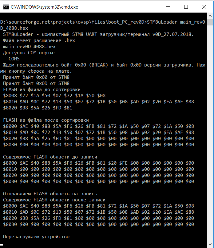
The code of the application program is stitched by the bootloader in FLASH memory, the device reboots. The LED starts blinking.
Examples of source codes of dumps that the host program sends to the loader for execution in RAM:
In the source code of the host program, these same dumps are present in the following form:
Previous article: “How to compress a bootloader for STM8 to 18 bytes in FLASH memory” .
Site with the project http://nflic.ru/STM8/STM8uLoader/000.html .
Project at https://sourceforge.net/projects/ovsp .
Project at https://github.com/ovsp/STM8uLoader .
I ask readers of targeted criticism and suggestions to further reduce the code.
The version of the $ 0D bootloader has been allocated to a separate branch. The main requirement for this version is to compress the code as much as possible. To date, the code size in FLASH memory is 8 bytes in the EEPROM memory is 35 bytes.
Let me remind the architecture of the STM8uLoader bootloader. The loader consists of the boot_PC program host and the boot_uC code in the STM8 memory. The latter is divided into the boot copier's boot_FLASH code in FLASH memory and the boot_EEPROM (or boot_OPTION) code in the EEPROM (or OPTION Bytes).
After the RESET event, the boot copier boot_FLASH is started, transfers the boot_EEPROM (or boot_OPTION) code image of the boot loader to the RAM and transfers control to it. The bootloader configures the UART transfers the host program a byte with its version number and, if it does not receive information from the program host during the timeout, transfers control to the application program in the FLASH memory. Either it transfers the code of the application program from the EEPROM memory (or the OPTION Bytes area) to the RAM memory and transfers control to it.
')
If, after the host program sends a byte with the version number, the bootloader receives a code dump via UART, it places it in the RAM memory and transfers control. The received code dump performs its current task: reading / copying / erasing / writing STM8 cells, transferring control to a specified address with preliminary initialization of the STM8 core registers, transferring control to the initial loader to change the current dump in the RAM memory by the host program.
The initial copyist boot_FLASH rev. $ 0D is located at $ 8000 ... $ 8007 and fully occupies the RESET and TRAP (Software interrupt) vectors. The rest of the space is $ 8008 ... $ 9FFF of FLASH memory is fully accessible to the application program. The interrupt vector table is also in place.
Consider the copyist code:
; boot_FLASH $0D($88) ; $4087($4187) ; $00 ; segment byte at 8000-8007 'bootF_rev0D' ; $8000 RESET Reset vector dc.b $AE, $40 ; [AE 40 88] ldw X,#$4088 ; dc.b $AE, $41 ; [AE 41 88] ldw X,#$4188 cycle: ; ; push A ldw X,#$4088($4188) push A ; [88] decw X ; [5A] ; $8004 TRAP Software interrupt ld A, (X) ; [F6] jrne cycle ; [26 FB] ret ; [81] ; $8008 TLI IRQ0 External top level interrupt The code of two commands intersects here: the ldw X command, # $ 4088 (ldw X, # $ 4188) and the push A commands. The first time the loop is entered, the ldw X command, # $ 4088 (ldw X, # $ 4188) is executed, and the push A command is not executed . This solution saved one byte, but led to a narrowing of the table storage area with an image of the initial loader code. The low byte of the $ 88 table address does not allow placing it in the OPTION Bytes area. For the STM8S103F3 model, only the addresses $ 4088 and $ 4188 in the EEPROM memory are available to accommodate the specified table. For owners of STM8S003F3 with EEPROM memory of 128 bytes ($ 4000 ... $ 407F) and these addresses are not available. For them, there is still a loophole.
You only need to swap the push A and decw X commands:
; boot_FLASH $0D($5A) ; $405A($415A, $425A) ; $00 ; segment byte at 8000-8007 'bootF_rev0D' ; $8000 RESET Reset vector dc.b $AE, $40 ; [AE 40 5A] ldw X,#$405A STM8S003F3 ; dc.b $AE, $41 ; [AE 41 5A] ldw X,#$415A ; dc.b $AE, $41 ; [AE 42 5A] ldw X,#$425A cycle: ; ; decw X ldw X,#$405A($415A, $425A) decw X ; [5A] push A ; [88] ; $8004 TRAP Software interrupt ld A, (X) ; [F6] jrne cycle ; [26 FB] ret ; [81] ; $8008 TLI IRQ0 External top level interrupt Here, when first entering the loop, the ldw X command, # $ 405A ($ 415A, $ 425A) is executed, and the decw X command is not executed.
Recall that in the RESET event, the SP pointer to the top of the stack is hardware initialized to $ 03FF. The stack grows in the direction of decreasing addresses. To fill the stack from the tail, the table with the bootloader code will also be read from the tail, hence the decw X command. The image of the bootloader code is appropriately located in the EEPROM memory.
To save the abandoned cycle counter. We agreed that the image of the bootloader code will have a zero byte only at the beginning of the table, and the control transfer address of the application program (which may have a zero byte) will be moved out of the table. At each iteration, we read a byte from the table, and if it is not zero, push it onto the stack. The read zero byte is a condition for exiting the loop.
The ret command here means to transfer control to the address that is contained in the two bytes that were last hit on the stack. Consider now the bootloader code:
; boot_EEPROM $0D($88) segment byte at 4067-4089 'bootE_rev0D_88' ; segment byte at 417B-4189 'bootE_rev0D_88' ; $4067 terminator RAM dc.b $00 ; [00] ; $4068 ($03E0) {RAM END - 31} ; {$0400 - (bootE_go_adr - bootE_start) } dc.w $03E2 ; [03 E2] $4067 - $3C85 = $03E2 ; UART 96001N8 ; BREAK $0D bootE_start: ; $406A ($03E2) {RAM END - 29} ld A, #%00001101 ; [A6 0D] ld UART1_BRR1, A ; [C7 52 32] ld UART1_CR2, A ; [C7 52 35] ld UART1_DR, A ; [C7 52 31] ; 243 ; n ; $4075 ($03ED) {RAM END - 18} bootE_rx_byte: incw X ; [5C] jreq bootE_exit ; [27 0C] btjf UART1_SR, #5, bootE_rx_byte ; [72 0B 52 30 F8] push UART1_DR ; [3B 52 31] ; clrw X ; [5F] inc A ; [4C] jrne bootE_rx_byte ; [26 F2] ; ; $02F1 ( $FE $02) ret ; [81] ; $4084 ($03FC) {RAM END - 3} bootE_exit: jp [bootE_go_adr] ; [72 CC 40 88] RAM END ; ; $4088 RAM bootE_go_adr: dc.w main_flash ; [80 08] The brackets show the code addresses after copying to the stack. The first is the zero byte, in memory RAM is not copied. Next comes the control transfer address to the initial loader, in fact, this is the address of the next cell in the RAM memory. This pair is put onto the stack, but then overwritten as unnecessary by the code of the next dump from the host program. All subsequent code is also copied to the stack, except for a pair with the address of control transfer to the application program.
Next comes the UART initialization. Here in all three registers fit the same number $ 0D. In the first case, this is the UART speed (16000000/8/9600/16 = 13). In the second case, this is the transmission / reception resolution, here the locomotive caught the one-time generation of the BREAK event. In the latter case, this is sending the loader version to the host program. In fact, the host program will receive two bytes of $ 00 (BREAK event) and $ 0D (bootloader version number) - this is a signal that you can send a dump with a code.
Register A with the contents of $ 0D then serves as a counter of received bytes and counts them with an increment to zero, which is equivalent to 243 received bytes. It is with this size that the host program must send dumps with code.
The index register X in the initial copier counted to $ 4,068. Now, with an increment, it will also count to zero (there are still 49048 left) counting the time allotted for the work to the initial loader. During this time, the initial loader must have time to accept a dump with a code of 243 bytes in order to push it further onto the stack and transfer control to it. Otherwise, control will be transferred to the application program and you will have to press the reset button again and restart the host program.
After transferring control to the received dump, the boot loader code remains on the stack and re-takes control when the host program decides to replace the dump with the code. Any accepted code dump is located on the stack at $ 02ED ... $ 03DF and takes control at $ 02F0. The bootloader code is located on the stack in the addresses $ 03E0 ... $ 03FF, initially takes control at $ 03E0, and if necessary it is possible to replace the dump with the code at $ 03E8.
The control transfer command to an application program is in the stack at $ 03FB.
The cell with the address $ 03FF can be used by the current dump.
The entire source code of the initial copier and bootloader in STM8 version $ 0D with a table in the EEPROM memory in the addresses $ 4039 ... $ 405C ($ 4139 ... $ 415C, $ 4239 ... $ 425C).
File bootF_rev0D_5A.asm:
stm8/ TITLE “bootF_rev0D_5A.asm” MOTOROLA WORDS .NOLIST ; #include "STM8S003F.inc" #include "STM8S103F.inc" .LIST ; boot_EEPROM $0D($5A) segment byte at 4039-405C 'bootE_rev0D_405A' ; STM8S003F ; segment byte at 4139-415C 'bootE_rev0D_415A' ; segment byte at 4239-425C 'bootE_rev0D_425A' ; $403A9 ($03DD) {RAM END - 34} terminator RAM ????? dc.b $00 ; [00] ; $403A ($03DE) {RAM END - 33} ; {$0400 - (bootE_go_adr - bootE_start - 1) } dc.w $03E0 ; [03 E0] ; UART 96001N8 ; BREAK $0D bootE_start: ; $403C ($03E0) {RAM END - 31} ld A, #%00001101 ; [A6 0D] ld UART1_BRR1, A ; [C7 52 32] ld UART1_CR2, A ; [C7 52 35] ; $4044 ($03E8) {RAM END - 23} ld UART1_DR, A ; [C7 52 31] ; 243 ; n ; $40487 ($03EB) {RAM END - 20} bootE_rx_byte: incw X ; [5C] jreq bootE_exit ; [27 0C] btjf UART1_SR, #5, bootE_rx_byte ; [72 0B 52 30 F8] push UART1_DR ; [3B 52 31] clrw X ; [5F] inc A ; [4C] jrne bootE_rx_byte ; [26 F2] ; ; $02EF ( $EF $02) ; $4056 ($03FA) {RAM END - 5} ret ; [81] ; $4057 ($03FB) {RAM END - 4} bootE_exit: jp [bootE_go_adr] ; [72 CC 40 5B] {RAM END - 1} ; ($03FF) RAM END ; ; $405B RAM bootE_go_adr: dc.w main_flash ; [80 08] ; boot_FLASH $0D($5A) ; $405A($415A,$425A) ; $00 ; segment byte at 8000-8007 'bootF_rev0D' ; $8000 RESET Reset vector dc.b $AE, $40 ; [AE 40 5A] ldw X,#$405A ; STM8S003F ; dc.b $AE, $41 ; [AE 41 5A] ldw X,#$415A ; dc.b $AE, $42 ; [AE 42 5A] ldw X,#$425A cycle: ; ; dec X ldw X,#$405A($415A,$425A) decw X ; [5A] push A ; [88] ; $8004 TRAP Software interrupt ld A, (X) ; [F6] jrne cycle ; [26 FB] ret ; [81] ; $8008 TLI IRQ0 External top level interrupt ; segment byte at 8008 'main_flash' main_flash: jra * ; [20 FE] ; end ; bootF_rev0D_5A.asm The entire source code of the initial copier and bootloader in STM8 version $ 0D with a table in the EEPROM memory at addresses $ 4,065 ... $ 4,088 ($ 4,165 ... $ 4,188).
File bootF_rev0D_88.asm:
stm8/ TITLE “bootF_rev0D_88.asm” MOTOROLA WORDS .NOLIST ; #include "STM8S003F.inc" #include "STM8S103F.inc" .LIST ; boot_EEPROM $0D($88) segment byte at 4065-4088 'bootE_rev0D_88' ; segment byte at 4165-4188 'bootE_rev0D_88' ; $4065 terminator RAM dc.b $00 ; [00] ; $4066 ($03DE) {RAM END - 33} ; {$0400 - (bootE_go_adr - bootE_start) } dc.w $03E0 ; [03 E0] ; UART 9600 1N8 ; BREAK $0D bootE_start: ; $4068 ($03E0) {RAM END - 31} ld A, #%00001101 ; [A6 0D] ld UART1_BRR1, A ; [C7 52 32] ld UART1_CR2, A ; [C7 52 35] ; $4070 ($03E8) {RAM END - 23} ld UART1_DR, A ; [C7 52 31] ; 243 ; n ; $4073 ($03EB) {RAM END - 20} bootE_rx_byte: incw X ; [5C] jreq bootE_exit ; [27 0C] btjf UART1_SR, #5, bootE_rx_byte ; [72 0B 52 30 F8] push UART1_DR ; [3B 52 31] clrw X ; [5F] inc A ; [4C] jrne bootE_rx_byte ; [26 F2] ; ; $02EF ( $EF $02) ; $4082 ($03FA) {RAM END - 5} ret ; [81] ; $4083 ($03FB) {RAM END - 4} bootE_exit: jp [bootE_go_adr] ; [72 CC 40 87] {RAM END - 1} ; ($03FF) RAM END ; ; $4087 ($4088 ) RAM bootE_go_adr: dc.w main_flash ; [80 08] ; boot_FLASH $0D($88) ; $4087($4187) ; $00 ; segment byte at 8000-8007 'bootF_rev0D' ; $8000 RESET Reset vector dc.b $AE, $40 ; [AE 40] ldw X,#$4088 ; dc.b $AE, $41 ; [AE 41] ldw X,#$4188 cycle: ; ; push A ldw X,#$4088($4188) push A ; [88] decw X ; [5A] ; $8004 TRAP Software interrupt ld A, (X) ; [F6] jrne cycle ; [26 FB] ret ; [81] ; $8008 TLI IRQ0 External top level interrupt ; segment byte at 8008 'main_flash' main_flash: jra * ; [20 FE] end ; bootF_rev0D_88.asm Sketch a simple application program for execution in STM8 FLASH memory.
File main_rev0D.asm:
stm8/ TITLE “main_rev0D.asm” MOTOROLA WORDS .NOLIST #include "STM8S103F.inc" .LIST ; segment byte at 8008-9FFF 'main_flash' main_flash: main_cycle: ; bset PB_DDR,#5 ; bset PB_CR1,#5 ; callr flash_delay ; bres PB_DDR,#5 ; bres PB_CR1,#5 ; callr flash_delay jra main_cycle flash_delay: ldw X, #35000 flash_delay_cycle: decw X jrne flash_delay_cycle ret end ; main_rev0D.asm We program the bootloader in STM8 with the programmer. We connect the board to the USB-TTL (UART) adapter. Run the batch file runSTM8uLoader.bat . Push the reset button on the board. Observe the result:
The code of the application program is stitched by the bootloader in FLASH memory, the device reboots. The LED starts blinking.
Examples of source codes of dumps that the host program sends to the loader for execution in RAM:
File Read_128000v0D.asm:
stm8/ TITLE "Read_128000v0D.asm" MOTOROLA WORDS .NOLIST #include "STM8S103F3P.inc" .LIST ; 243 ; $02EE...$03DF ; ( $03DF:$03E0 ) ; $02F0 ; $03E1...$03FE ; $03E1 ( 9600, A<=$0D SP<=$03E0 X<=$0000) ; $03E9 ( , A<=$0D SP<=$03E8 X<=$0000) ; $03FB segment byte at 0000-00F2 'ram0' dc.w $02F0 start: ; UART1 / 9600, (8 , , 1 ) mov UART1_BRR2, #0 ; [35 00 52 33] Fmaster=16/8=2 128000 mov UART1_BRR1, #1 ; [35 0D 52 32] Fmaster=16/8=2 128000 mov UART1_CR2, #%00001100 ; [35 0C 52 35] UART1_CR2.TEN <- 1 UART1_CR2.REN <- 1 / main_cycle: wait_byte_adrH_cmnd: btjf UART1_SR, #5, wait_byte_adrH_cmnd ld A, UART1_DR cp A, #$EF JRUGT wait_byte_cmd_test ; Relative jump if Unsigned Greater Than ld XH, A ; XH ld UART1_DR, A ; tx_echo_adrH: btjf UART1_SR, #7, tx_echo_adrH ; skip if UART1_SR.TXE = 0 TXE: Transmit data register empty wait_byte_adrL: btjf UART1_SR, #5, wait_byte_adrL ld A, UART1_DR ld XL, A ; XL wait_byte_cntr: btjf UART1_SR, #5, wait_byte_cntr ld A, #$00 ld YH, A ; ld A, UART1_DR ld YL, A ; ; bset PB_DDR,#5 ; bset PB_CR1,#5 ; ; read_block_cycle: ld A, (X) ld UART1_DR, A wait_tx: btjf UART1_SR, #7, wait_tx ; skip if UART1_SR.TXE = 0 TXE: Transmit data register empty incw X decw Y jrne read_block_cycle ; bres PB_DDR,#5 ; bres PB_CR1,#5 ; jra main_cycle ; $F0 wait_byte_cmd_test: cp A, #$F5 ; jreq echo_F5cmd wait_tx_err: mov UART1_DR, #$F1 ; btjf UART1_SR, #7, wait_tx_err ; skip if UART1_SR.TXE = 0 TXE: Transmit data register empty jra main_cycle echo_F5cmd: ld UART1_DR, A ; wait_tx_echo_F5cmd: btjf UART1_SR, #7, wait_tx_echo_F5cmd ; skip if UART1_SR.TXE = 0 TXE: Transmit data register empty ; GoAdr wait_byte_adrH_toM; btjf UART1_SR, #5, wait_byte_adrH_toM mov $03E7, UART1_DR wait_byte_adrL_toM; btjf UART1_SR, #5, wait_byte_adrL_toM mov $03E8, UART1_DR ; SP wait_byte_adrH_toSP; btjf UART1_SR, #5, wait_byte_adrH_toSP ld A, UART1_DR ld XH, A wait_byte_adrL_toSP; btjf UART1_SR, #5, wait_byte_adrL_toSP ld A, UART1_DR ld XL, A ldw SP, X ; Y wait_byte_adrH_toY; ; btjf UART1_SR, #5, wait_byte_adrH_toY ; ld A, UART1_DR ; ld YH, A wait_byte_adrL_toY; ; btjf UART1_SR, #5, wait_byte_adrL_toY ; ld A, UART1_DR ; ld YL, A ; X wait_byte_adrH_toX; btjf UART1_SR, #5, wait_byte_adrH_toX ld A, UART1_DR ld XH, A wait_byte_adrL_toX; btjf UART1_SR, #5, wait_byte_adrL_toX ld A, UART1_DR ld XL, A ; A wait_byte_cntr_toA; btjf UART1_SR, #5, wait_byte_cntr_toA ld A, UART1_DR jp [$03E7.w] SKIP 59, $00 ; dc.b $00 dc.b $00 end ; Read_128000v0D.asm WriteBlocks_FLASH_128000v0D.asm file:
stm8/ TITLE "WriteBlocks_FLASH_128000v0D.asm" MOTOROLA WORDS .NOLIST #include "STM8S103F3P.inc" .LIST ; 243 ; $02EE...$03DF ; ( $03DF:$03E0 ) ; $02F0 ; $03E1...$03FE ; $03E1 ( 9600, A<=$0D SP<=$03E0 X<=$0000) ; $03E9 ( , A<=$0D SP<=$03E8 X<=$0000) ; $03FB segment byte at 0000-00F2 'ram0' dc.w $02F0 start: ; UART1 / 9600, (8 , , 1 ) mov UART1_BRR2, #0 ; [35 00 52 33] Fmaster=16/8=2 128000 mov UART1_BRR1, #1 ; [35 0D 52 32] Fmaster=16/8=2 128000 mov UART1_CR2, #%00001100 ; [35 0C 52 35] UART1_CR2.TEN <- 1 UART1_CR2.REN <- 1 / main_cycle: wait_byte_adrH_cmnd: btjf UART1_SR, #5, wait_byte_adrH_cmnd ld A, UART1_DR cp A, #$F0 JRUGE wait_byte_cmd_test ; Relative jump if Unsigned Greater or Equal ld XH, A ; XH ld UART1_DR, A ; tx_echo_adrH: btjf UART1_SR, #7, tx_echo_adrH ; skip if UART1_SR.TXE = 0 TXE: Transmit data register empty wait_byte_adrL: btjf UART1_SR, #5, wait_byte_adrL ld A, UART1_DR ld XL, A ; XL wait_byte_cntr: btjf UART1_SR, #5, wait_byte_cntr ; mov $03FF, UART1_DR write_block_cycle: ldw Y, #64 ; ; unlock FLASH memory (writing the correct MASS keys) mov FLASH_PUKR, #$56 ; Write $56 then $AE in FLASH_PUKR($5062) mov FLASH_PUKR, #$AE ; If wrong keys have been entered, another key programming sequence can be issued without resetting the device. ; FLASH Block programming mode mov FLASH_CR2, #$01 mov FLASH_NCR2, #$FE ; ; FLASH Word programming mode ; mov FLASH_CR2, #$40 ; mov FLASH_NCR2, #$BF ; else FLASH byte programming ; bset PB_DDR,#5 ; bset PB_CR1,#5 ; ; ; wait_rx_byte: btjf UART1_SR, #5, wait_rx_byte ld A, UART1_DR ld (X), A incw X decw Y jrne wait_rx_byte mov UART1_DR, #$FA ; OK wait_tx_OK_FA: btjf UART1_SR, #7, wait_tx_OK_FA ; skip if UART1_SR.TXE = 0 TXE: Transmit data register empty ; bres PB_DDR,#5 ; bres PB_CR1,#5 ; dec $03FF jrne write_block_cycle jra main_cycle ; $F0 wait_byte_cmd_test: cp A, #$F5 ; boot_OPTION jreq echo_F5cmd wait_tx_err: mov UART1_DR, #$F1 ; wait_tx_err_F1: btjf UART1_SR, #7, wait_tx_err_F1 ; skip if UART1_SR.TXE = 0 TXE: Transmit data register empty jra main_cycle echo_F5cmd: ld UART1_DR, A ; boot_OPTION wait_tx_echo_F5cmd: btjf UART1_SR, #7, wait_tx_echo_F5cmd ; skip if UART1_SR.TXE = 0 TXE: Transmit data register empty ; GoAdr wait_byte_adrH_toM; btjf UART1_SR, #5, wait_byte_adrH_toM mov $03E7, UART1_DR wait_byte_adrL_toM; btjf UART1_SR, #5, wait_byte_adrL_toM mov $03E8, UART1_DR ; SP wait_byte_adrH_toSP; btjf UART1_SR, #5, wait_byte_adrH_toSP ld A, UART1_DR ld XH, A wait_byte_adrL_toSP; btjf UART1_SR, #5, wait_byte_adrL_toSP ld A, UART1_DR ld XL, A ldw SP, X ; Y wait_byte_adrH_toY; ; btjf UART1_SR, #5, wait_byte_adrH_toY ; ld A, UART1_DR ; ld YH, A wait_byte_adrL_toY; ; btjf UART1_SR, #5, wait_byte_adrL_toY ; ld A, UART1_DR ; ld YL, A ; X wait_byte_adrH_toX; btjf UART1_SR, #5, wait_byte_adrH_toX ld A, UART1_DR ld XH, A wait_byte_adrL_toX; btjf UART1_SR, #5, wait_byte_adrL_toX ld A, UART1_DR ld XL, A ; A wait_byte_cntr_toA; btjf UART1_SR, #5, wait_byte_cntr_toA ld A, UART1_DR jp [$03E7.w] SKIP 28, $00 ; dc.b $00 dc.b $00 end ; WriteBlocks_FLASH_128000v0D.asm File Reset_128000v0D.asm:
stm8/ TITLE "Reset_128000v0D.asm" MOTOROLA WORDS .NOLIST #include "STM8S103F3P.inc" .LIST ; 243 ; $02EE...$03DF ; ( $03DF:$03E0 ) ; $02F0 ; $03E1...$03FE ; $03E1 ( 9600, A<=$0D SP<=$03E0 X<=$0000) ; $03E9 ( , A<=$0D SP<=$03E8 X<=$0000) ; $03FB segment byte at 0000-00F2 'ram0' dc.w $02F0 start: ; RESET ldw X, #$03FF ldw SP, X clrw X clrw Y clr A jp $8000 SKIP 230, $00 end ; Reset_128000v0D.asm In the source code of the host program, these same dumps are present in the following form:
public readonly static byte[] Read_128000v0D = { 0x00, 0x00, 0x00, 0x00, 0x00, 0x00, 0x00, 0x00, 0x00, 0x00, 0x00, 0x00, 0x00, 0x00, 0x00, 0x00, 0x00, 0x00, 0x00, 0x00, 0x00, 0x00, 0x00, 0x00, 0x00, 0x00, 0x00, 0x00, 0x00, 0x00, 0x00, 0x00, 0x00, 0x00, 0x00, 0x00, 0x00, 0x00, 0x00, 0x00, 0x00, 0x00, 0x00, 0x00, 0x00, 0x00, 0x00, 0x00, 0x00, 0x00, 0x00, 0x00, 0x00, 0x00, 0x00, 0x00, 0x00, 0x00, 0x00, 0x00, 0x00, 0xE7, 0x03, 0xCC, 0x72, 0x31, 0x52, 0xC6, 0xFB, 0x30, 0x52, 0x0B, 0x72, 0x97, 0x31, 0x52, 0xC6, 0xFB, 0x30, 0x52, 0x0B, 0x72, 0x95, 0x31, 0x52, 0xC6, 0xFB, 0x30, 0x52, 0x0B, 0x72, 0x94, 0x97, 0x31, 0x52, 0xC6, 0xFB, 0x30, 0x52, 0x0B, 0x72, 0x95, 0x31, 0x52, 0xC6, 0xFB, 0x30, 0x52, 0x0B, 0x72, 0xE8, 0x03, 0x31, 0x52, 0x55, 0xFB, 0x30, 0x52, 0x0B, 0x72, 0xE7, 0x03, 0x31, 0x52, 0x55, 0xFB, 0x30, 0x52, 0x0B, 0x72, 0xFB, 0x30, 0x52, 0x0F, 0x72, 0x31, 0x52, 0xC7, 0xA5, 0x20, 0xF7, 0x30, 0x52, 0x0F, 0x72, 0x31, 0x52, 0xF1, 0x35, 0x0B, 0x27, 0xF5, 0xA1, 0xB4, 0x20, 0x08, 0x50, 0x1B, 0x72, 0x07, 0x50, 0x1B, 0x72, 0xF2, 0x26, 0x5A, 0x90, 0x5C, 0xFB, 0x30, 0x52, 0x0F, 0x72, 0x31, 0x52, 0xC7, 0xF6, 0x08, 0x50, 0x1A, 0x72, 0x07, 0x50, 0x1A, 0x72, 0x97, 0x90, 0x31, 0x52, 0xC6, 0x95, 0x90, 0x00, 0xA6, 0xFB, 0x30, 0x52, 0x0B, 0x72, 0x97, 0x31, 0x52, 0xC6, 0xFB, 0x30, 0x52, 0x0B, 0x72, 0xFB, 0x30, 0x52, 0x0F, 0x72, 0x31, 0x52, 0xC7, 0x95, 0x40, 0x22, 0xEF, 0xA1, 0x31, 0x52, 0xC6, 0xFB, 0x30, 0x52, 0x0B, 0x72, 0x35, 0x52, 0x0C, 0x35, 0x32, 0x52, 0x01, 0x35, 0x33, 0x52, 0x00, 0x35, 0xF0, 0x02 }; public readonly static byte[] WriteBlocks_FLASH_128000v0D = { 0x00, 0x00, 0x00, 0x00, 0x00, 0x00, 0x00, 0x00, 0x00, 0x00, 0x00, 0x00, 0x00, 0x00, 0x00, 0x00, 0x00, 0x00, 0x00, 0x00, 0x00, 0x00, 0x00, 0x00, 0x00, 0x00, 0x00, 0x00, 0x00, 0x00, 0xE7, 0x03, 0xCC, 0x72, 0x31, 0x52, 0xC6, 0xFB, 0x30, 0x52, 0x0B, 0x72, 0x97, 0x31, 0x52, 0xC6, 0xFB, 0x30, 0x52, 0x0B, 0x72, 0x95, 0x31, 0x52, 0xC6, 0xFB, 0x30, 0x52, 0x0B, 0x72, 0x94, 0x97, 0x31, 0x52, 0xC6, 0xFB, 0x30, 0x52, 0x0B, 0x72, 0x95, 0x31, 0x52, 0xC6, 0xFB, 0x30, 0x52, 0x0B, 0x72, 0xE8, 0x03, 0x31, 0x52, 0x55, 0xFB, 0x30, 0x52, 0x0B, 0x72, 0xE7, 0x03, 0x31, 0x52, 0x55, 0xFB, 0x30, 0x52, 0x0B, 0x72, 0xFB, 0x30, 0x52, 0x0F, 0x72, 0x31, 0x52, 0xC7, 0x86, 0x20, 0xFB, 0x30, 0x52, 0x0F, 0x72, 0x31, 0x52, 0xF1, 0x35, 0x0B, 0x27, 0xF5, 0xA1, 0x95, 0x20, 0xBF, 0x26, 0xFF, 0x03, 0x5A, 0x72, 0x08, 0x50, 0x1B, 0x72, 0x07, 0x50, 0x1B, 0x72, 0xFB, 0x30, 0x52, 0x0F, 0x72, 0x31, 0x52, 0xFA, 0x35, 0xF2, 0x26, 0x5A, 0x90, 0x5C, 0xF7, 0x31, 0x52, 0xC6, 0xFB, 0x30, 0x52, 0x0B, 0x72, 0x08, 0x50, 0x1A, 0x72, 0x07, 0x50, 0x1A, 0x72, 0x5C, 0x50, 0xFE, 0x35, 0x5B, 0x50, 0x01, 0x35, 0x62, 0x50, 0xAE, 0x35, 0x62, 0x50, 0x56, 0x35, 0x40, 0x00, 0xAE, 0x90, 0xFF, 0x03, 0x31, 0x52, 0x55, 0xFB, 0x30, 0x52, 0x0B, 0x72, 0x97, 0x31, 0x52, 0xC6, 0xFB, 0x30, 0x52, 0x0B, 0x72, 0xFB, 0x30, 0x52, 0x0F, 0x72, 0x31, 0x52, 0xC7, 0x95, 0x5F, 0x24, 0xF0, 0xA1, 0x31, 0x52, 0xC6, 0xFB, 0x30, 0x52, 0x0B, 0x72, 0x35, 0x52, 0x0C, 0x35, 0x32, 0x52, 0x01, 0x35, 0x33, 0x52, 0x00, 0x35, 0xF0, 0x02 }; public readonly static byte[] Reset_128000v0D = { 0x00, 0x00, 0x00, 0x00, 0x00, 0x00, 0x00, 0x00, 0x00, 0x00, 0x00, 0x00, 0x00, 0x00, 0x00, 0x00, 0x00, 0x00, 0x00, 0x00, 0x00, 0x00, 0x00, 0x00, 0x00, 0x00, 0x00, 0x00, 0x00, 0x00, 0x00, 0x00, 0x00, 0x00, 0x00, 0x00, 0x00, 0x00, 0x00, 0x00, 0x00, 0x00, 0x00, 0x00, 0x00, 0x00, 0x00, 0x00, 0x00, 0x00, 0x00, 0x00, 0x00, 0x00, 0x00, 0x00, 0x00, 0x00, 0x00, 0x00, 0x00, 0x00, 0x00, 0x00, 0x00, 0x00, 0x00, 0x00, 0x00, 0x00, 0x00, 0x00, 0x00, 0x00, 0x00, 0x00, 0x00, 0x00, 0x00, 0x00, 0x00, 0x00, 0x00, 0x00, 0x00, 0x00, 0x00, 0x00, 0x00, 0x00, 0x00, 0x00, 0x00, 0x00, 0x00, 0x00, 0x00, 0x00, 0x00, 0x00, 0x00, 0x00, 0x00, 0x00, 0x00, 0x00, 0x00, 0x00, 0x00, 0x00, 0x00, 0x00, 0x00, 0x00, 0x00, 0x00, 0x00, 0x00, 0x00, 0x00, 0x00, 0x00, 0x00, 0x00, 0x00, 0x00, 0x00, 0x00, 0x00, 0x00, 0x00, 0x00, 0x00, 0x00, 0x00, 0x00, 0x00, 0x00, 0x00, 0x00, 0x00, 0x00, 0x00, 0x00, 0x00, 0x00, 0x00, 0x00, 0x00, 0x00, 0x00, 0x00, 0x00, 0x00, 0x00, 0x00, 0x00, 0x00, 0x00, 0x00, 0x00, 0x00, 0x00, 0x00, 0x00, 0x00, 0x00, 0x00, 0x00, 0x00, 0x00, 0x00, 0x00, 0x00, 0x00, 0x00, 0x00, 0x00, 0x00, 0x00, 0x00, 0x00, 0x00, 0x00, 0x00, 0x00, 0x00, 0x00, 0x00, 0x00, 0x00, 0x00, 0x00, 0x00, 0x00, 0x00, 0x00, 0x00, 0x00, 0x00, 0x00, 0x00, 0x00, 0x00, 0x00, 0x00, 0x00, 0x00, 0x00, 0x00, 0x00, 0x00, 0x00, 0x00, 0x00, 0x00, 0x00, 0x00, 0x00, 0x00, 0x00, 0x00, 0x00, 0x00, 0x00, 0x00, 0x00, 0x00, 0x00, 0x00, 0x00, 0x80, 0xCC, 0x4F, 0x5F, 0x90, 0x5F, 0x94, 0xFF, 0x03, 0xAE, 0xF0, 0x02 }; Previous article: “How to compress a bootloader for STM8 to 18 bytes in FLASH memory” .
Site with the project http://nflic.ru/STM8/STM8uLoader/000.html .
Project at https://sourceforge.net/projects/ovsp .
Project at https://github.com/ovsp/STM8uLoader .
I ask readers of targeted criticism and suggestions to further reduce the code.
Source: https://habr.com/ru/post/418483/
All Articles