OSPF (Part One)
This article was written for myself, if necessary, to quickly refresh your memory and deal with theory. I decided to publish it, maybe it will be useful for someone, or maybe I am mistaken in some way.
In this article we will try to understand the theory of the operation of the OSPF protocol. We will not delve into the history and process of creating a protocol, this information is abundant in almost every article on OSPF. We will try to understand in more detail how the OSPF protocol works and how it builds its routing table. It is important to give a general definition of the protocol:
OSPF (English Open Shortest Path First) is a dynamic routing protocol based on link-state technology and using Dijkstra's algorithm to find the shortest path.
')
The question immediately arises - What is the technology of channel status tracking? This name is not entirely successful. It turned out that there are two types of dynamic routing protocols: Link-state and Distance-Vector. Consider their principles of work:
In Distance-Vector protocols, the router learns information about routes through routers directly connected to the same network segment. That is, the router has information about the topology only within the boundaries of its neighboring routers and has no idea how the topology behind these routers is arranged, being guided only by metrics. In Link-state protocols, each router should not easily know the best routes to all remote networks, but also have in memory a complete network map with all existing connections between other routers as well. This is achieved by building a special base LSDB, but more on that later.
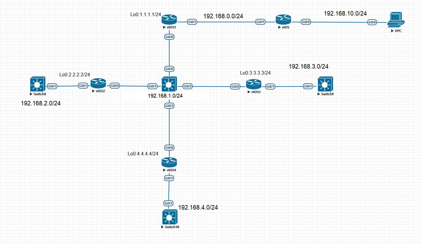
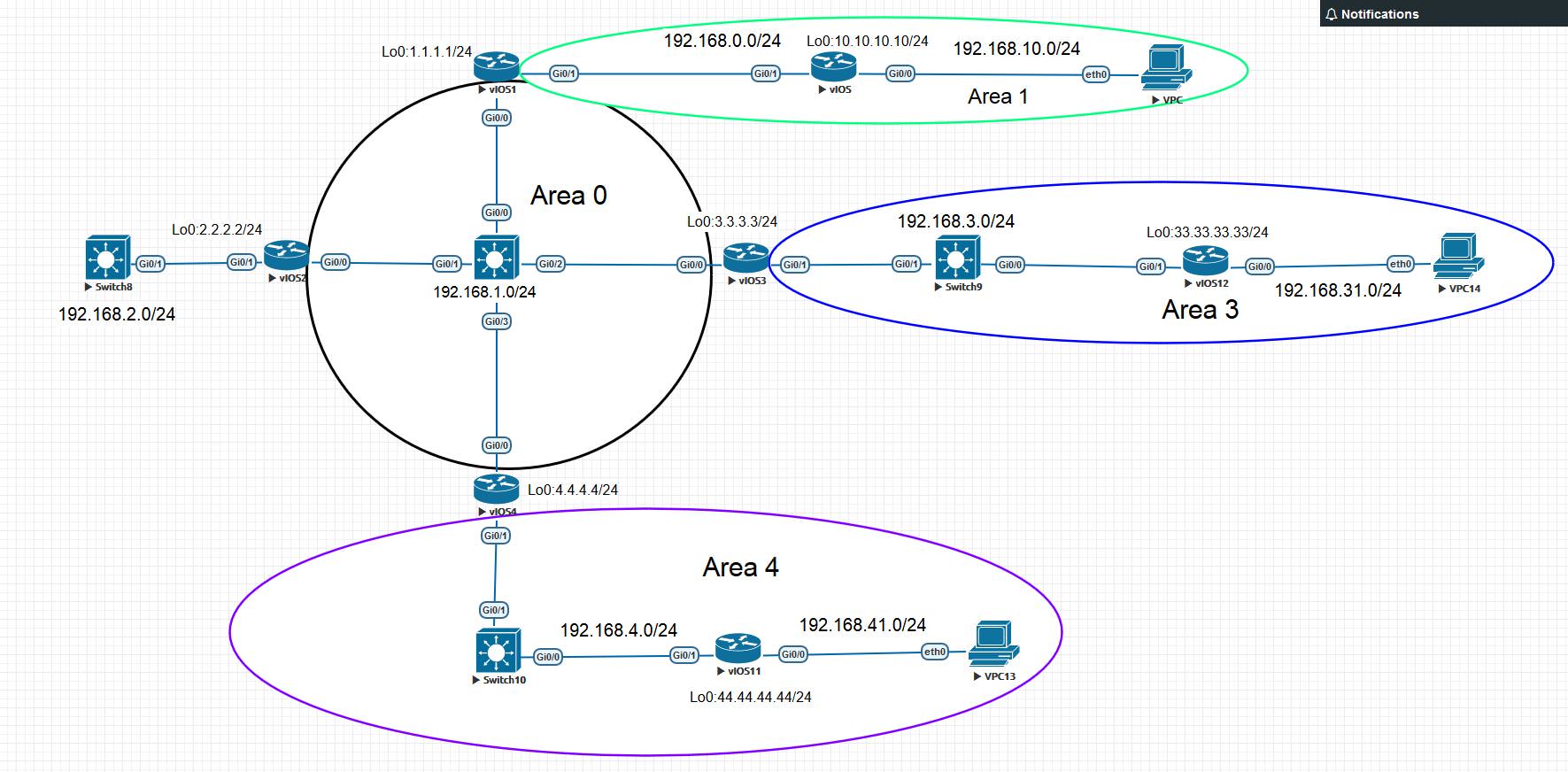
So let's start with how LSDB is built from which the router learns about all-all routes? We construct the initial topology for study. It looks like this:
We will configure OSPF. How does OSPF start? Establishing Neighborhood between Routers — After OSPF is activated on router interfaces, routers start sending Hello messages. This message is sent to the multicast address - 224.0.0.5 every 10 seconds (Hello Timer). We will first enable OSPF on the router vIOS1.
Let's see what the Hello package looks like:
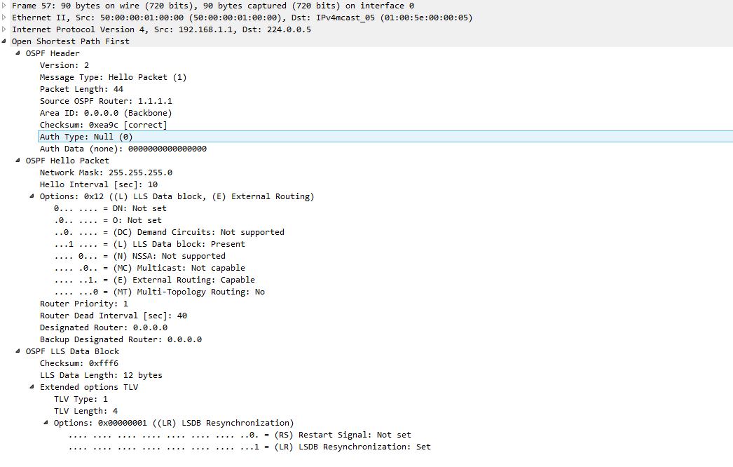
The message is important to pay attention to such fields as Area ID, Source OSPF Router. When you start the OSPF process, the Router ID is selected, which is required to identify the router among the remaining OSPF routers. The rules for selecting this parameter are as follows:
1. Configured by the special router-id ABCD command - in the ip address format.
2. One loopback interface and several interfaces with different addresses are configured:
3. Several loopback interfaces are configured with multiple IP addresses in each:
4. Several interfaces are configured with an IP address on each:
We now turn to the Field ID field — this is the more important and fundamental concept in OSPF. To work with a large number of routers, OSPF uses zones. Each of the interfaces of the router must belong to any one zone. In our topology, the Gi0 / 0 interfaces of the vIOS1, vIOS2, vIOS3, and vIOS4 routers belong to zone 0. Area 0 is called Backbone and is the center for all other zones. Every other zone must be connected to the Backbone zone (virtual-link is not considered yet). In the further analysis, these concepts will become clearer.
So, we enabled OSPF on vIOS1 and it started sending Hello packets every 10 seconds. We enable OSPF on vIOS2 and see how neighborhood relationships are established.
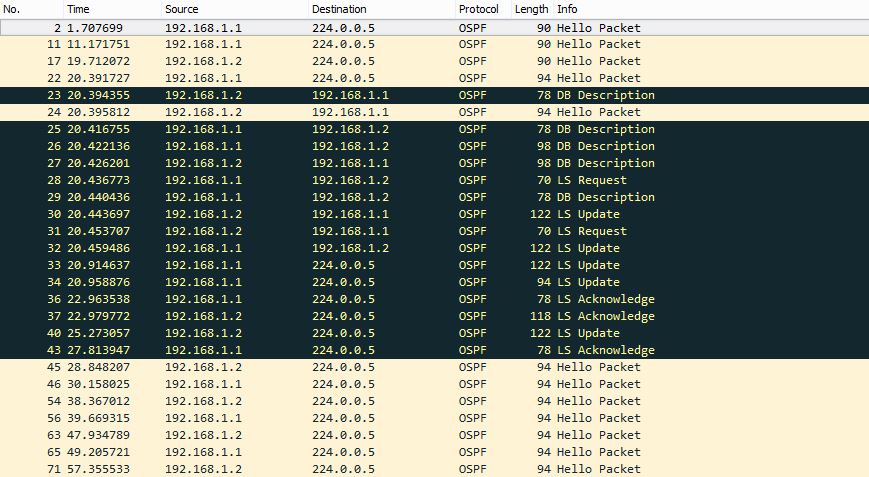
So, closely monitor the sequence of messages. First, Hello sends only router 1.1.1.1 (192.168.1.1), as soon as we enable OSPF to 192.168.1.2, the Hello packet will be sent. vIOS1 and vIOS2 will receive Hello packets from each other and in order for the neighborhood to take place it is important that the following parameters are the same in the OSPF configuration on both routers:
If you look at the Hello package shown above, all these parameters are listed in the Hello package. As soon as one of the routers (vIOS1) receives a new Hello-packet and verifies all the conditions, it immediately sends a Hello-packet, where it indicates the address of the new router (vIOS2) in the Active Neighbor field, and after receiving and seeing itself in the neighbors field, it adds vIOS1 to the neighbors and send the unicast package to 192.168.1.1 (vIOS1), where it will indicate it to the neighbor. So to say, they became neighbors and now the most interesting begins - the exchange of information and the construction of the very same LSDB base. About the establishment of the neighborhood I advise you to read the following article .
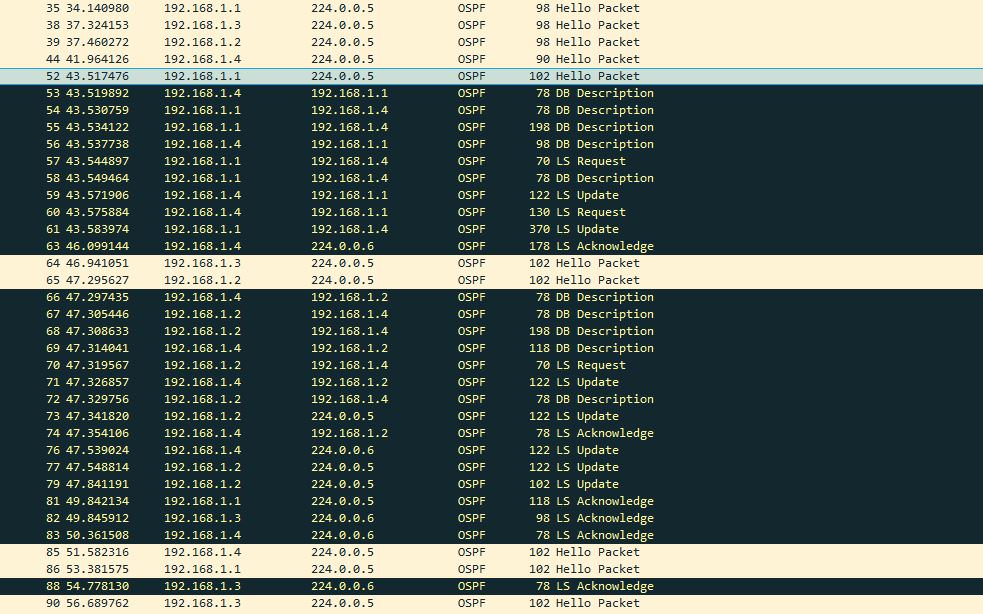
The LSDB base will contain information about the routes and this LSDB, after establishing a neighborhood, must be identical on all routers within the limits of a single zone. And, first of all, after the establishment of a neighborhood, routers begin the process of synchronizing their databases with each other (vIOS1 with vIOS2). As you can see, it all starts with exchanging the DB Description (DBD) messages. To make it clearer, let's talk about the types of messages that OSPF uses:
It is also important to introduce such a concept as LSA:
Link State Advertisement (LSA) is a data unit that describes the local state of a router or network. The set of all LSAs describing routers and networks form a link state database (LSDB). LSDB consists of several kinds of LSA. In great detail about each LSA is written in this article. DBD messages use quite a few flags to determine the state of synchronization, and these messages contain information about their own database. That is, vIOS1 reports in these messages that in my database there is information about networks such as 192.168.0 / 24, 1.1.1.0/24 (LSA Type 1), and vIOS2, in turn, reports that it has records of networks: 192.168.2.0/24, 2.2.2.0/24 (LSA Type 1). After receiving DBD messages, each router sends an LSAck in confirmation of the received message, and then compares the information in its neighbor’s database with its own. If it is found that it lacks any information, the router sends an LS Request, where it requests complete information about any LSA. For example, vIOS1 requested LS Request from vIOS2, vIOS2 sends LS Update in response, which already contains detailed information about each route. The LS Update is shown below:
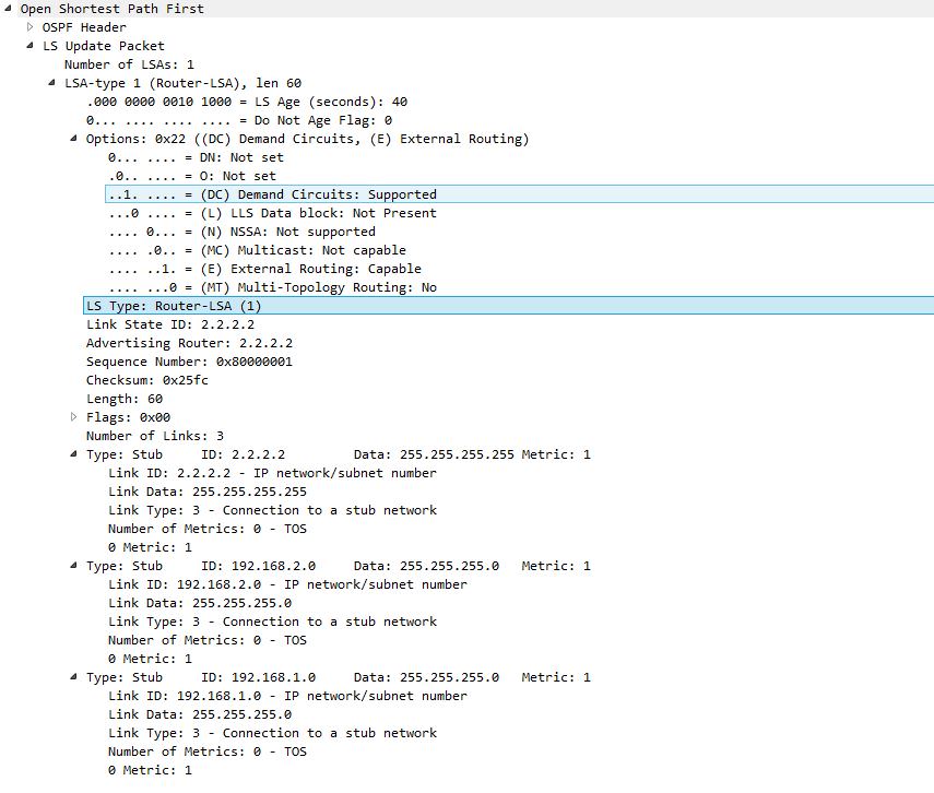
As you can see, in this message, vIOS2 tells about the known subnets and information associated with them. Also, viOS1 talks about its LSDB. And in the end, routers have the same LSDB. Once the process is complete, Dijkstra's algorithm (Shortest Path First) is launched. It calculates all known routes from LSDB and places the best of them into the routing table. The best one has the metric below, but more on that later.
Let us think about the question, what will happen if we activate OSPF on vIOS3? Since vIOS3 will have to build LSDB and synchronize it with other routers, the question arises with whom exactly to synchronize? With vIOS1 or vIOS2? With each separately? How optimal is it? Therefore, in OSPF there is such a thing as DR - Designated router. We introduce this concept:
Dedicated router (designated router, DR) - manages the process of sending LSA in the network. Each network router establishes a neighborhood relationship with DR. Information about changes in the network is sent to the DR, the router who detects this change, and the DR is responsible for ensuring that this information is sent to the rest of the network’s routers.
In other words, if a new router appears in the network segment, it will synchronize its LSDB with DR. It is also important to note that not only new, but all other routers will also report this to DR when the network changes or a new route appears, and the rest will take this information from DR. But then questions arise - What will happen if the DR fails? How is DR selected?
When it fails, a new DR should be selected. New neighborhood relationships must be formed, and until the router databases are synchronized with the new DR database, the network will not be available to forward packets. To eliminate this drawback, BDR is chosen - Backup designated router:
Backup dedicated router (backup designated router, BDR). Each network router establishes a neighborhood relationship not only with DR, but also with BDR. DR and BDR also establish neighborhood relationships with each other. When DR fails, the BDR becomes the DR and performs all its functions. Since the network routers have established a neighborhood relationship with the BDR, the network downtime is minimized. Thus, in our network we get not only DR, but also BDR. The remaining routers will only receive and report actual network information through them. DR and BDR is selected only within one segment, not zone! That is, one DR and BDR will be selected for the routers vIOS1, vIOS2, vIOS3, vIOS4, and, for example, their DR and BDR will be defined between vIOS and vIOS1 relative to their network segment, even if they are in the same Area 0. For communication with DR and BDR, routers use the multicast address — 224.0.0.6.
The next question is - How is DR / BDR selected? The following criteria apply:
Only now we can return to the question - what will happen if we activate OSPF on vIOS3? After activating OSPF, vIOS3 will start sending and listening to Hello packets. Receive Hello-packets from vIOS1 and vIOS2, which will indicate which routers are DR and BDR and understand with whom to synchronize LSDB. It is important to note that when a router with the best ID appears, the DR / BDR does not change until one of them fails. After that, vIOS3 begins to synchronize its LSDB with these routers.
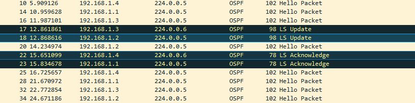
After receiving new information from vIOS3, DR sends LS Update messages to all routers to the address 224.0.0.5, to which the other routers receive a packet and send LS Acknowledge for the DR, but to the address 224.0.0.6 (the address for DR / BDR).
In the same way, we also connect vIOS4. After synchronization, all routers have the same LSDB. Let's see how the states of the neighborhood look like in vIOS3. Command show ip ospf neighbor:
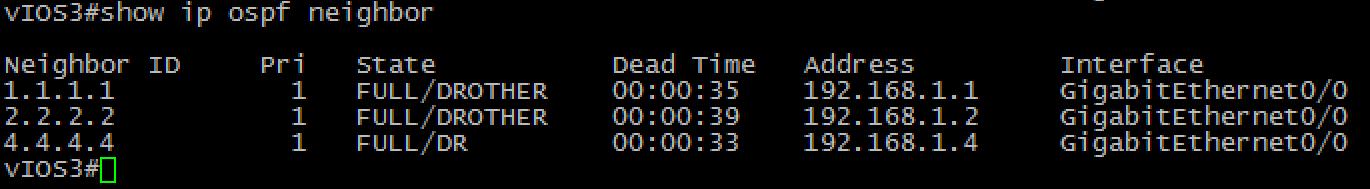
As we can see, DR is 2.2.2.2, BDR is 1.1.1.1, and with vIOS4, the state 2WAY / DROTHER is selected. About the states of the neighborhood link was given above .
But the state of the neighborhood on vIOS1 c established by the neighborhood c vIOS:
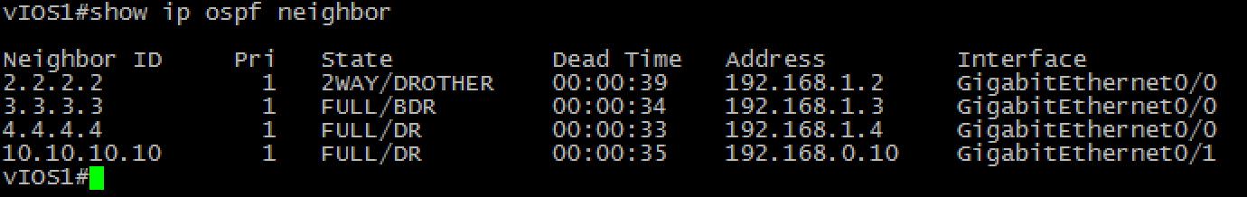
As you can see, he has two DRs because he has a neighbor in another network segment.
Consider how OSPF works when multiple zones are used. Let's change our topology by adding new routers:
Let's start by configuring OSPF on vIOS1 and vIOS so that their Gi0 / 1 interfaces on vIOS and vIOS1 will be in zone 1. Let's see what's changing. vIOS1 now has interfaces in both Area 0 (Gi0 / 0) and Area 1 (Gi0 / 0). Such a router is called ABR - Area Border Router (below we give a more correct definition of ABR). ABR will send information about routes from one zone to another. This is done through LSA Type 3:
Type 3 LSA - Network Summary LSA - the summary announcement of the status of network channels:
At its core, between zones, the protocol’s operation principle is reminiscent of the work of the Distance-vector protocol, transmitting only route information with a metric. Here is LS Update from vIOS1 in Area 0, which contains 3 pieces of LSA Type 3:
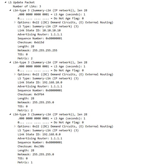
At its core, the structure of LSA Type 3 is not much different from LSA Type 1, but they have different effects on the operation of the protocol. When getting updated or when losing any LSA Type 1 & 2, the SPF (shortest-path calculation algorithm) is restarted and LSDB is recalculated.
When receiving LSA Type 3, this process does not occur - it turns out a route with a metric in LSA Type 3. This LSA stores data on which ABR this route was obtained (ABR is specified in the Advertising Router field) and the metric to reach this ABR already available in LSDB. Thus, the metric from LSA Type 3 is summed with the metric of the route to ABR and we get the ready route without restarting the SPF. This process is called Partial SPF calculation . This is quite important because in large networks, LSDB sizes can be quite large and often running SPF is not good. Also, the creation of LSA Type 3 says that changes and recalculation of LSDB are the affairs of one zone. ABR only reports that with some route what has changed.
It is also important to note that any route from a non-zero zone to any non-zero zone passes through Area 0. If there is an ABR, it cannot be not connected to Area 0 (we exclude the option with virtual-link). Area 0 is the core that connects all other zones and provides routing between zones. The ABR definition looks like this:
Border router (area border router, ABR) - connects one or more zones with the trunk zone and acts as a gateway for inter-zone traffic. The border router always has at least one interface belonging to the backbone. For each attached zone, the router maintains a separate link state database.
Understood with the establishment of a neighborhood, the creation of LSDB and SPF, with the usual area. Now let's deal with the convergence and response of OSPF to changes in the topology.
Let's look at our topology and imagine that vIOS3 has stopped working (the state of the channels has not changed). Helps in rebuilding the topology Dead Interval Timer - 40 seconds. If during this interval, the router does not receive the Hello-packet from the neighbor, then the neighborhood collapses. In our case, DR will send LS Update with LSA Type 2, where it will be indicated that there is no vIOS3 among the connected routers, this will result in the launch of SPF and recalculate LSDB already without LSA received from vIOS3. It is important to note that on a standard router of type vIOS4, even the exhaustion of Dead Interval Timer and the loss of neighborhood with vIOS3 does not lead to a recalculation of the topology, namely the LS Update message with LSA Type 2 starts this process.
Type 2 LSA - Network LSA - announcement of the status of network channels:
Thus, the disregard of data, which has ceased to work, occurs with the help of this message. This indication of neighbors is a trigger for discarding irrelevant routes.
Turn back on vIOS3 and set the neighborhood again. The next experiment will be the response to the shutdown of the Gi0 / 1 interface on vIOS3. As soon as the vIOS3 detects a link crash, it instantly sends LS Update to DR to the address 224.0.0.6, where it is reported that certain routes have been dropped by setting the LSA flag - LS Age equal to 3600 seconds. For LSDB, this is Max Age and all LSAs with Max Age are not taken into account in SPF, so they will not be in the routing table. The question arises: when Age LSA naturally reaches Max Age, what happens? To do this, OSPF has LSRefreshTime - equal to half of Max Age, and LS Update from the router is sent every 1800 seconds to update the timer data:
Then, having processed this LS Update, the DR sends to all other LS Update routers the address 224.0.0.5. As soon as the routers received new information, they send LSAck. This results in good convergence in OSPF.
The router chooses the best route based on the lowest metric value. However, OSPF takes several other factors into account when choosing a route. In this case, the source of the route and its type is important. Priority route selection is as follows:
Although the cost of the E2 route does not change when it is transferred by zones (the cost of the path to the ASBR is not added), if the cost of the E2 routes coincides, the cost of the path to the ASBR is compared, which announces the route. The metric is taken into account when you have to choose from routes of the same type. As a metric used such a thing as cost (cost). It is calculated by the formula:
cost = reference bandwidth / link bandwidth. Reference bandwidth - the basis of the bandwidth. The default on Cisco is 100Mbit.
ABR Loop Prevention. As we said above, between zones, the principle of OSPF operation is similar to the distance-vector protocol. Using the mechanisms of preventing loops, we can get that a non-optimal path is chosen. For example, between zones there is a rule similar to Split Horizon from distance-vector protocols. Consider this on an example, if we change our topology on the border of zones 0 and 4 like this:
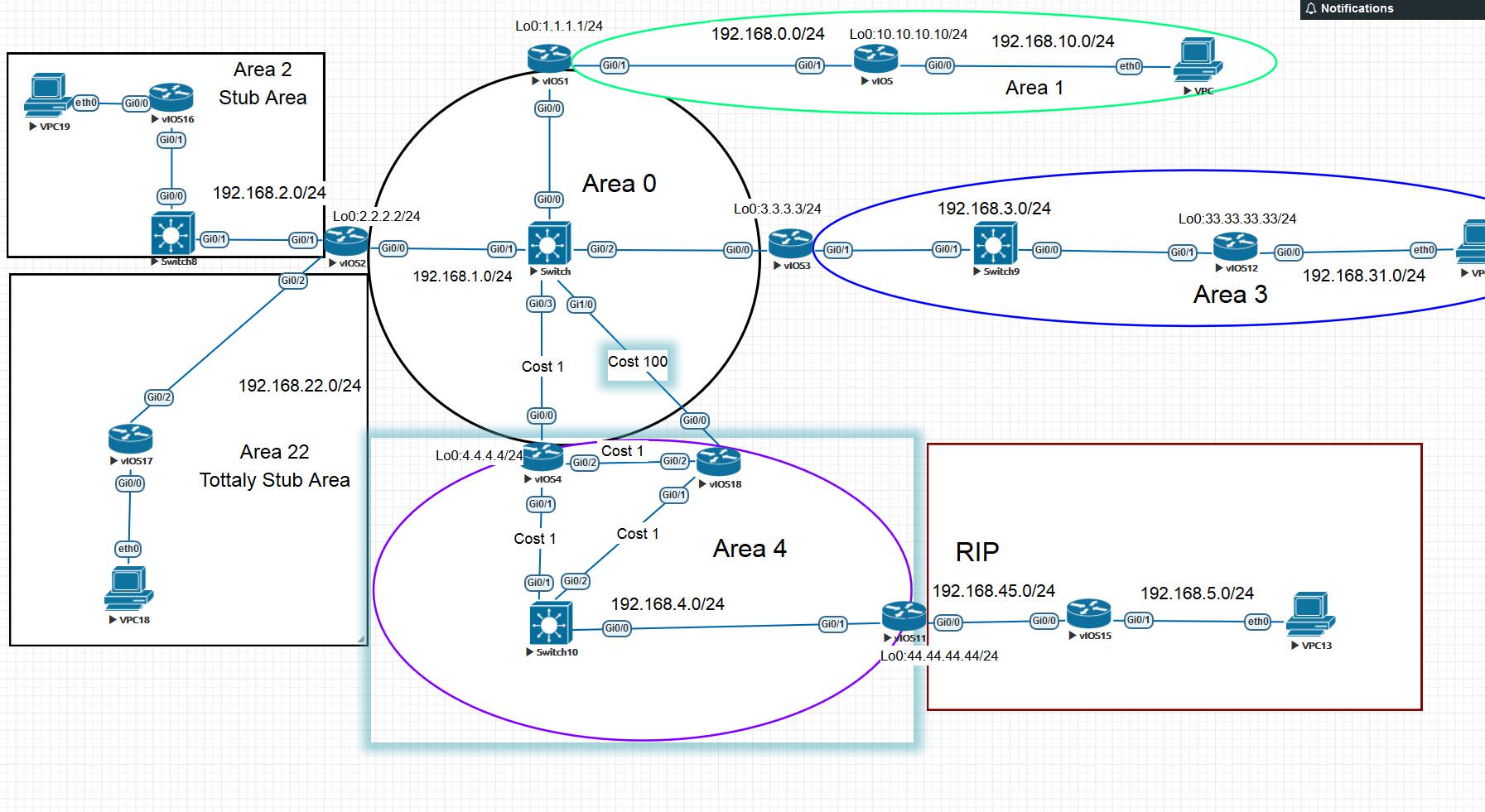
then we get that vIOS18 will choose the non-optimal path with metric 100 through the interface Gi0 / 0. This is due to the fact that vIOS18 will not take into account LSA Type 3, received not from zone 0. Also, the above rule prohibits sending the LSA Type 3 back to zone 0.
In this article we will try to understand the theory of the operation of the OSPF protocol. We will not delve into the history and process of creating a protocol, this information is abundant in almost every article on OSPF. We will try to understand in more detail how the OSPF protocol works and how it builds its routing table. It is important to give a general definition of the protocol:
OSPF (English Open Shortest Path First) is a dynamic routing protocol based on link-state technology and using Dijkstra's algorithm to find the shortest path.
')
The question immediately arises - What is the technology of channel status tracking? This name is not entirely successful. It turned out that there are two types of dynamic routing protocols: Link-state and Distance-Vector. Consider their principles of work:
In Distance-Vector protocols, the router learns information about routes through routers directly connected to the same network segment. That is, the router has information about the topology only within the boundaries of its neighboring routers and has no idea how the topology behind these routers is arranged, being guided only by metrics. In Link-state protocols, each router should not easily know the best routes to all remote networks, but also have in memory a complete network map with all existing connections between other routers as well. This is achieved by building a special base LSDB, but more on that later.
So let's start with how LSDB is built from which the router learns about all-all routes? We construct the initial topology for study. It looks like this:
We will configure OSPF. How does OSPF start? Establishing Neighborhood between Routers — After OSPF is activated on router interfaces, routers start sending Hello messages. This message is sent to the multicast address - 224.0.0.5 every 10 seconds (Hello Timer). We will first enable OSPF on the router vIOS1.
Let's see what the Hello package looks like:
The message is important to pay attention to such fields as Area ID, Source OSPF Router. When you start the OSPF process, the Router ID is selected, which is required to identify the router among the remaining OSPF routers. The rules for selecting this parameter are as follows:
1. Configured by the special router-id ABCD command - in the ip address format.
2. One loopback interface and several interfaces with different addresses are configured:
- The address assigned to the loopback interface will be Router ID.
3. Several loopback interfaces are configured with multiple IP addresses in each:
- The highest IP address assigned to any of the loopback interfaces will be the Router ID.
4. Several interfaces are configured with an IP address on each:
- The highest IP address of all active interfaces will be Router ID.
We now turn to the Field ID field — this is the more important and fundamental concept in OSPF. To work with a large number of routers, OSPF uses zones. Each of the interfaces of the router must belong to any one zone. In our topology, the Gi0 / 0 interfaces of the vIOS1, vIOS2, vIOS3, and vIOS4 routers belong to zone 0. Area 0 is called Backbone and is the center for all other zones. Every other zone must be connected to the Backbone zone (virtual-link is not considered yet). In the further analysis, these concepts will become clearer.
So, we enabled OSPF on vIOS1 and it started sending Hello packets every 10 seconds. We enable OSPF on vIOS2 and see how neighborhood relationships are established.
So, closely monitor the sequence of messages. First, Hello sends only router 1.1.1.1 (192.168.1.1), as soon as we enable OSPF to 192.168.1.2, the Hello packet will be sent. vIOS1 and vIOS2 will receive Hello packets from each other and in order for the neighborhood to take place it is important that the following parameters are the same in the OSPF configuration on both routers:
- Hello Interval - the frequency of sending messages Hello
- Router Dead Interval - a period of time after which the neighbor is considered to be inaccessible if there was no Hello.
- Area ID - the neighborhood can be established only through interfaces in one area.
- Authentication - the password used for authentication and the type of authentication, if any.
- Stub area flag - an optional flag that is installed on all routers that belong to a stub area
If you look at the Hello package shown above, all these parameters are listed in the Hello package. As soon as one of the routers (vIOS1) receives a new Hello-packet and verifies all the conditions, it immediately sends a Hello-packet, where it indicates the address of the new router (vIOS2) in the Active Neighbor field, and after receiving and seeing itself in the neighbors field, it adds vIOS1 to the neighbors and send the unicast package to 192.168.1.1 (vIOS1), where it will indicate it to the neighbor. So to say, they became neighbors and now the most interesting begins - the exchange of information and the construction of the very same LSDB base. About the establishment of the neighborhood I advise you to read the following article .
The LSDB base will contain information about the routes and this LSDB, after establishing a neighborhood, must be identical on all routers within the limits of a single zone. And, first of all, after the establishment of a neighborhood, routers begin the process of synchronizing their databases with each other (vIOS1 with vIOS2). As you can see, it all starts with exchanging the DB Description (DBD) messages. To make it clearer, let's talk about the types of messages that OSPF uses:
- Hello — used to detect neighbors, check parameters, build neighborhood relationships with them, and monitor accessibility.
- Database Description (DBD) - checks the synchronization status of databases on routers.
- Link-State Request (LSR) —Requires certain channel status records from the router to the router for synchronization.
- Link-State Update (LSU) - sends certain channel status records in response to a request.
- Link-State Acknowledgment (LSAck) - acknowledges receipt of other types of packets.
It is also important to introduce such a concept as LSA:
Link State Advertisement (LSA) is a data unit that describes the local state of a router or network. The set of all LSAs describing routers and networks form a link state database (LSDB). LSDB consists of several kinds of LSA. In great detail about each LSA is written in this article. DBD messages use quite a few flags to determine the state of synchronization, and these messages contain information about their own database. That is, vIOS1 reports in these messages that in my database there is information about networks such as 192.168.0 / 24, 1.1.1.0/24 (LSA Type 1), and vIOS2, in turn, reports that it has records of networks: 192.168.2.0/24, 2.2.2.0/24 (LSA Type 1). After receiving DBD messages, each router sends an LSAck in confirmation of the received message, and then compares the information in its neighbor’s database with its own. If it is found that it lacks any information, the router sends an LS Request, where it requests complete information about any LSA. For example, vIOS1 requested LS Request from vIOS2, vIOS2 sends LS Update in response, which already contains detailed information about each route. The LS Update is shown below:
As you can see, in this message, vIOS2 tells about the known subnets and information associated with them. Also, viOS1 talks about its LSDB. And in the end, routers have the same LSDB. Once the process is complete, Dijkstra's algorithm (Shortest Path First) is launched. It calculates all known routes from LSDB and places the best of them into the routing table. The best one has the metric below, but more on that later.
Let us think about the question, what will happen if we activate OSPF on vIOS3? Since vIOS3 will have to build LSDB and synchronize it with other routers, the question arises with whom exactly to synchronize? With vIOS1 or vIOS2? With each separately? How optimal is it? Therefore, in OSPF there is such a thing as DR - Designated router. We introduce this concept:
Dedicated router (designated router, DR) - manages the process of sending LSA in the network. Each network router establishes a neighborhood relationship with DR. Information about changes in the network is sent to the DR, the router who detects this change, and the DR is responsible for ensuring that this information is sent to the rest of the network’s routers.
In other words, if a new router appears in the network segment, it will synchronize its LSDB with DR. It is also important to note that not only new, but all other routers will also report this to DR when the network changes or a new route appears, and the rest will take this information from DR. But then questions arise - What will happen if the DR fails? How is DR selected?
When it fails, a new DR should be selected. New neighborhood relationships must be formed, and until the router databases are synchronized with the new DR database, the network will not be available to forward packets. To eliminate this drawback, BDR is chosen - Backup designated router:
Backup dedicated router (backup designated router, BDR). Each network router establishes a neighborhood relationship not only with DR, but also with BDR. DR and BDR also establish neighborhood relationships with each other. When DR fails, the BDR becomes the DR and performs all its functions. Since the network routers have established a neighborhood relationship with the BDR, the network downtime is minimized. Thus, in our network we get not only DR, but also BDR. The remaining routers will only receive and report actual network information through them. DR and BDR is selected only within one segment, not zone! That is, one DR and BDR will be selected for the routers vIOS1, vIOS2, vIOS3, vIOS4, and, for example, their DR and BDR will be defined between vIOS and vIOS1 relative to their network segment, even if they are in the same Area 0. For communication with DR and BDR, routers use the multicast address — 224.0.0.6.
The next question is - How is DR / BDR selected? The following criteria apply:
- DR: The router with the highest OSPF interface priority.
- BDR: Router with the second highest priority of the OSPF interface.
- If the priorities of the OSPF interfaces are equal, the highest router ID is used to make the selection. As we said, routers define their Router-ID. In the beginning, when OSPF was launched on vIOS1 and vIOS2, in addition to establishing a neighborhood, DR / BDR elections also took place. In this dispute, I won vIOS2 with ID - 2.2.2.2, when vIOS1 had ID - 1.1.1.1. vIOS1 was selected as BDR. It is important to note that the DR and BDR selection process does not take place immediately after receiving the first Hello packets from the second router. For this there is a special timer equal to the Router Dead Interval - 40 seconds. If during this time the Hello-package with the best ID is not received, then a selection will be made based on the existing Hello-packages.
Only now we can return to the question - what will happen if we activate OSPF on vIOS3? After activating OSPF, vIOS3 will start sending and listening to Hello packets. Receive Hello-packets from vIOS1 and vIOS2, which will indicate which routers are DR and BDR and understand with whom to synchronize LSDB. It is important to note that when a router with the best ID appears, the DR / BDR does not change until one of them fails. After that, vIOS3 begins to synchronize its LSDB with these routers.
After receiving new information from vIOS3, DR sends LS Update messages to all routers to the address 224.0.0.5, to which the other routers receive a packet and send LS Acknowledge for the DR, but to the address 224.0.0.6 (the address for DR / BDR).
In the same way, we also connect vIOS4. After synchronization, all routers have the same LSDB. Let's see how the states of the neighborhood look like in vIOS3. Command show ip ospf neighbor:
As we can see, DR is 2.2.2.2, BDR is 1.1.1.1, and with vIOS4, the state 2WAY / DROTHER is selected. About the states of the neighborhood link was given above .
But the state of the neighborhood on vIOS1 c established by the neighborhood c vIOS:
As you can see, he has two DRs because he has a neighbor in another network segment.
Multizone
Consider how OSPF works when multiple zones are used. Let's change our topology by adding new routers:
Let's start by configuring OSPF on vIOS1 and vIOS so that their Gi0 / 1 interfaces on vIOS and vIOS1 will be in zone 1. Let's see what's changing. vIOS1 now has interfaces in both Area 0 (Gi0 / 0) and Area 1 (Gi0 / 0). Such a router is called ABR - Area Border Router (below we give a more correct definition of ABR). ABR will send information about routes from one zone to another. This is done through LSA Type 3:
Type 3 LSA - Network Summary LSA - the summary announcement of the status of network channels:
- Ad is distributed by border routers
- Ad describes routes to networks outside the local area.
- Contains information about networks and the cost of the path to these networks, but does not send information about the network topology
- By default, the border router sends a separate advertisement for each network it knows about. If necessary, ABR networks may be summarized.
- Link-state ID - the network number of the destination.
At its core, between zones, the protocol’s operation principle is reminiscent of the work of the Distance-vector protocol, transmitting only route information with a metric. Here is LS Update from vIOS1 in Area 0, which contains 3 pieces of LSA Type 3:
At its core, the structure of LSA Type 3 is not much different from LSA Type 1, but they have different effects on the operation of the protocol. When getting updated or when losing any LSA Type 1 & 2, the SPF (shortest-path calculation algorithm) is restarted and LSDB is recalculated.
When receiving LSA Type 3, this process does not occur - it turns out a route with a metric in LSA Type 3. This LSA stores data on which ABR this route was obtained (ABR is specified in the Advertising Router field) and the metric to reach this ABR already available in LSDB. Thus, the metric from LSA Type 3 is summed with the metric of the route to ABR and we get the ready route without restarting the SPF. This process is called Partial SPF calculation . This is quite important because in large networks, LSDB sizes can be quite large and often running SPF is not good. Also, the creation of LSA Type 3 says that changes and recalculation of LSDB are the affairs of one zone. ABR only reports that with some route what has changed.
It is also important to note that any route from a non-zero zone to any non-zero zone passes through Area 0. If there is an ABR, it cannot be not connected to Area 0 (we exclude the option with virtual-link). Area 0 is the core that connects all other zones and provides routing between zones. The ABR definition looks like this:
Border router (area border router, ABR) - connects one or more zones with the trunk zone and acts as a gateway for inter-zone traffic. The border router always has at least one interface belonging to the backbone. For each attached zone, the router maintains a separate link state database.
Understood with the establishment of a neighborhood, the creation of LSDB and SPF, with the usual area. Now let's deal with the convergence and response of OSPF to changes in the topology.
Let's look at our topology and imagine that vIOS3 has stopped working (the state of the channels has not changed). Helps in rebuilding the topology Dead Interval Timer - 40 seconds. If during this interval, the router does not receive the Hello-packet from the neighbor, then the neighborhood collapses. In our case, DR will send LS Update with LSA Type 2, where it will be indicated that there is no vIOS3 among the connected routers, this will result in the launch of SPF and recalculate LSDB already without LSA received from vIOS3. It is important to note that on a standard router of type vIOS4, even the exhaustion of Dead Interval Timer and the loss of neighborhood with vIOS3 does not lead to a recalculation of the topology, namely the LS Update message with LSA Type 2 starts this process.
Type 2 LSA - Network LSA - announcement of the status of network channels:
- Distributed by DR in multiple access networks
- Network LSA is not created for networks in which DR is not selected.
- Distributed only within the same zone.
- Link-state ID - DR interface IP address
Thus, the disregard of data, which has ceased to work, occurs with the help of this message. This indication of neighbors is a trigger for discarding irrelevant routes.
Turn back on vIOS3 and set the neighborhood again. The next experiment will be the response to the shutdown of the Gi0 / 1 interface on vIOS3. As soon as the vIOS3 detects a link crash, it instantly sends LS Update to DR to the address 224.0.0.6, where it is reported that certain routes have been dropped by setting the LSA flag - LS Age equal to 3600 seconds. For LSDB, this is Max Age and all LSAs with Max Age are not taken into account in SPF, so they will not be in the routing table. The question arises: when Age LSA naturally reaches Max Age, what happens? To do this, OSPF has LSRefreshTime - equal to half of Max Age, and LS Update from the router is sent every 1800 seconds to update the timer data:
Then, having processed this LS Update, the DR sends to all other LS Update routers the address 224.0.0.5. As soon as the routers received new information, they send LSAck. This results in good convergence in OSPF.
Choosing the best route
The router chooses the best route based on the lowest metric value. However, OSPF takes several other factors into account when choosing a route. In this case, the source of the route and its type is important. Priority route selection is as follows:
- Internal routes of the zone (intra-area)
- Routes between zones (interarea)
- External routes type 1 (E1)
- External routes type 2 (E2)
Although the cost of the E2 route does not change when it is transferred by zones (the cost of the path to the ASBR is not added), if the cost of the E2 routes coincides, the cost of the path to the ASBR is compared, which announces the route. The metric is taken into account when you have to choose from routes of the same type. As a metric used such a thing as cost (cost). It is calculated by the formula:
cost = reference bandwidth / link bandwidth. Reference bandwidth - the basis of the bandwidth. The default on Cisco is 100Mbit.
ABR Loop Prevention. As we said above, between zones, the principle of OSPF operation is similar to the distance-vector protocol. Using the mechanisms of preventing loops, we can get that a non-optimal path is chosen. For example, between zones there is a rule similar to Split Horizon from distance-vector protocols. Consider this on an example, if we change our topology on the border of zones 0 and 4 like this:
then we get that vIOS18 will choose the non-optimal path with metric 100 through the interface Gi0 / 0. This is due to the fact that vIOS18 will not take into account LSA Type 3, received not from zone 0. Also, the above rule prohibits sending the LSA Type 3 back to zone 0.
Source: https://habr.com/ru/post/418391/
All Articles