The organization of network interaction of physical and virtual machines
In this article, I’ll tell you about the experience of building network interaction between physical computers and virtual machines created in the VMWare Esxi 6.7 environment. The organization of routing between all devices by using Mikrotik CHR.
And so, let's start
Introduction
In some cases, it is sometimes necessary to combine physical machines into a single network infrastructure with virtual machines. At the same time, to ensure isolation of each address space from each other, but to provide access to shared virtual machines from any device within the infrastructure.
I will give the original topology.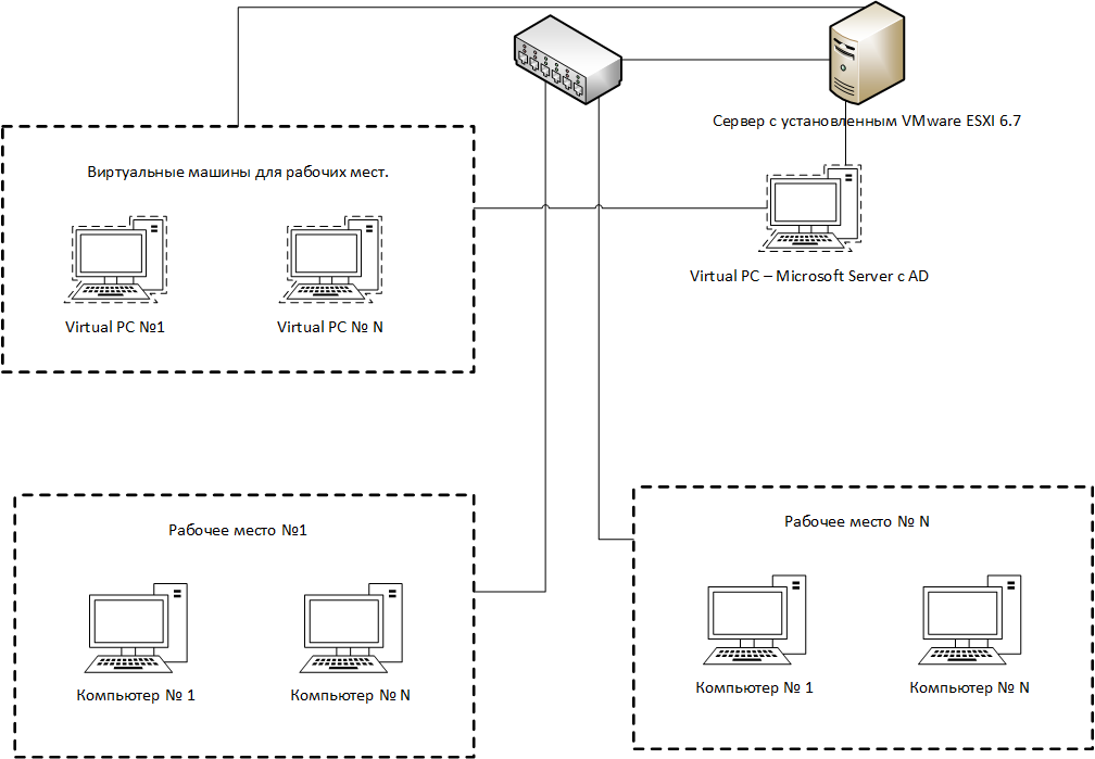
What we have:
- D-Link Switch Physical machines and a server with VMWare ESXI are connected to it. The switch itself is connected to the organization’s superior equipment.
- Some fleet of physical machines.
- A set of virtual machines.
- One virtual machine on which Windows Server and AD are installed.
Task
It is necessary to combine 2 physical machines and 2 virtual machines into one address space. At the same time it is impossible to affect the overall infrastructure of the organization. Each set of machines must be isolated from each other, but must be provided with Internet access and access to AD.
Implementation
Initially, we start by saying that on the switch the ports to which the physical machines are connected will be placed in our own VLANs that are not in the infrastructure of the organization. The result is that in each VLAN there are two physical machines. Further we will prevent all created VLAN on the server where VMWare is installed.
On the virtual switch VMWare we get the following structure:

In order to organize the routing and subnetting use Mikrotik CHR. On the VMWare server, we will post the created VLANs between the virtual machines and Mikrotik. As a result, we get the following view for each VLAN:

New topology with Mikrotik CHR is as follows:

As a result, the following interfaces come to the virtual router:
- Interface to access the organization’s internal network
- Interface with real IP addresses
- Interface of each VLAN created
Mikrotik CHR setup
For all interfaces created on the router, add a comment and define the name.
/interface ethernet set [ find default-name=ether1 ] comment="VLAN ID 361 Uplink to Org" name=Class_VM set [ find default-name=ether2 ] comment="Interface Vlan 2025 Real_Outside" name=Real_Outside set [ find default-name=ether3 ] comment="Interface WSR_4001 for StudentWSR #1" name=WSR_4001 set [ find default-name=ether4 ] comment="Interface WSR_4002 for StudentWSR #2" name=WSR_4002 set [ find default-name=ether5 ] comment="Interface WSR_4003 for StudentWSR #3" name=WSR_4003 set [ find default-name=ether6 ] comment="Interface WSR_4004 for StudentWSR #4" name=WSR_4004 set [ find default-name=ether7 ] comment="Interface WSR_4005 for StudentWSR #5" name=WSR_4005 set [ find default-name=ether8 ] comment="Interface WSR_4006 for StudentWSR #6" name=WSR_4006 set [ find default-name=ether9 ] comment="Interface WSR_4007 for WinServerDC" name=WSR_4007 /interface list add comment="Interface List All Local Vlan" name=local_vm /interface list member add interface=WSR_4001 list=local_vm add interface=WSR_4002 list=local_vm add interface=WSR_4003 list=local_vm add interface=WSR_4004 list=local_vm add interface=WSR_4005 list=local_vm add interface=WSR_4006 list=local_vm add disabled=yes interface=WSR_4007 list=local_vm Now for each interface we can define our own address space, in each address space the DNS server will be a virtual machine with Windows Server and AD. Thus, each device can be added to the created AD. Inside AD, we also specify the organization’s DNS server.
/ip address add address=*.*.*.*/27 interface=Class_VM network=*.*.*.* add address=10.0.35.1/29 interface=WSR_4001 network=10.0.35.0 add address=10.0.36.1/29 interface=WSR_4002 network=10.0.36.0 add address=10.0.37.1/29 interface=WSR_4003 network=10.0.37.0 add address=10.0.38.1/29 interface=WSR_4004 network=10.0.38.0 add address=10.0.39.1/29 interface=WSR_4005 network=10.0.39.0 add address=10.0.40.1/29 interface=WSR_4006 network=10.0.40.0 add address=10.0.41.1/29 interface=WSR_4007 network=10.0.41.0 add address=*.*.*.*/27 interface=Real_Outside network=*.*.*.* To ensure the isolation of each subnet from each other, we will create a corresponding rule, but at the same time provide access to the network where the Windows Server with AD is located (forward chain). We also prohibit ICMP packets between networks (input chain).
/ip firewall filter add action=accept chain=forward in-interface-list=local_vm out-interface=WSR_4007 add action=accept chain=forward in-interface=WSR_4007 out-interface-list=local_vm add action=drop chain=input comment="Block ping between interface" in-interface-list=local_vm protocol=\ icmp add action=drop chain=forward comment="Block traffic between interface" in-interface-list=local_vm \ out-interface-list=local_vm /ip firewall nat add action=masquerade chain=srcnat out-interface=Class8_509_VM To simplify the work, we place the necessary interfaces into one list, thereby providing convenience in configuring the firewall.
After all the settings, we get the following situation from the DHCP server:

As you can see the machines occupy addresses from certain networks.
Total
Using virtual Mikrotik CHR provides the ability to interact between physical machines and virtual. Separating each set of machines into their own address space allows you to isolate the created objects.
')
Source: https://habr.com/ru/post/418265/
All Articles