Using JavaScript Functions to Build 3D Models
This article discusses the use of a geometric library of WebGeometry functions for building models of complex polyhedra. The library is written in Javascript. A link to GitHub with an example that shows the simplest example of using a library. Comments and criticism are welcome.
To display models that were previously calculated using functions from the WebGeometry library, use the ThreeJS library. HTML5 canvas (canvas) is used to display individual flat elements of models and display auxiliary information on the screen.
WebGL technology and libraries created on its basis, such as ThreeJS and BadylonJS, are used on the Internet for realizing a variety of purposes related to 3D graphics. But mostly they are used to display in the browser ready-made three-dimensional models (previously created, for example, in 3ds Max or Blender programs). If we are faced with the task of creating a parametric model, that is, a model in which, in the process of displaying an object in the browser, we can change its individual elements by setting the appropriate model parameters (for example, increase the angle of a certain face), we need to have a set of geometric functions that will allow you to create a model in such a way that in the future it will be possible to interactively vary the shape of individual model elements or the whole model as a whole. To solve this problem, we need a set of functions in the Javascript language, which will implement the methods used in analytical geometry. The library must have functions for creating straight lines, planes and circles, finding points (or straight lines) that intersect them, creating inclined planes, and more. In the ThreeJS and BadylonJS libraries, some of these features are present, but the number of actions performed using them will not allow you to perform all the arising tasks when building a parametric model. There are several other purely mathematical Javascript libraries. Of these, the most widespread are glMatrix and Sylvester . The glMatrix library is mainly designed to work with vectors, matrices, and quaternions, but there are no functions for working with straight lines and planes. The Sylvester library has these functions, but they are present in a rather limited number. However, there are several books in which the implementation of methods of analytic geometry in C / C ++ is described. Corresponding C / C ++ programs can be used as prototypes when creating a Javascript math library. Therefore, when I decided to create three-dimensional parametric models of diamond cut-outs for displaying them in the browser, the library ThreeJS was chosen by me only to display already calculated models on the screen — it was not used to calculate the shape of the models. WebGeometry library was created for the form calculation itself. The basis of this library was taken earlier by the geometric functions I used in C / C ++, which I translated into the Javascript language. Consider the stages of building a model of a pyramid (cut diamond type Pyramid).
')
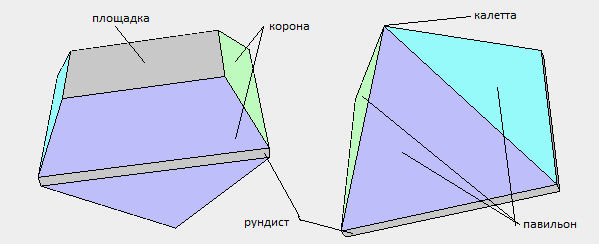
At the first stage, we need to draw the intended view of the model and then number its vertices. The figure below shows the numbering of the vertices and the names of the cut elements of the pyramid cut model.

After that, it is required to form faces from the numbered vertices. For example, the following sequence of vertices should be written for the face of the site and the edges of the crown (the duplicated first vertex of the face indicates that the face has ended):
Bypassing faces should be counterclockwise. The pyramid_index.js file contains source code for traversing all faces of the pyramid and detailed comments. The result of the traversal is written to the index_cut array.
At the second stage, we can color the faces of the model. This step is optional if we do not need coloring. Suppose we want to color the pyramid model as follows:
For this purpose, a pyramid_colors.js file is created in which the facet_colors () function is located which writes the colors of all faces to the colors array.
At the third stage , after all the vertices are numbered and the sequences of traversing all the vertices of the faces are written, you must set the model parameters and then calculate the coordinates of all its vertices. Of course, it is assumed that we have already outlined a construction algorithm for ourselves and have figured out how all faces of the model will be located in space. For the pyramid, we will select the following parameters, which will set the dimensions of both its individual parts and the model as a whole:
The choice of parameters is determined by the model developer. For example, instead of setting two parameters for two corners of the inclination of the crown, you can set a single parameter for two angles at once — then these angles will always be the same. You can enter a parameter that determines the size of the site. In this case, it is necessary either not to set the height of the crown, or not to set the inclination of its faces. Another option for selecting parameters is to make some parameters computable. In this case, when changing some parameters, some others may change their initial value. For example, if we assume that for the pyramid we defined one parameter to set the angle of the crown faces, another parameter for the crown height and another parameter that will define the size of the area, then when we change the inclination of the faces, we will have to change either the size of the area or crown height. On the other hand, if you change the parameter specifying the size of the platform, the value of the parameter specifying either the height or the slope of the crown faces will automatically change. The option associated with the use of calculated parameters in this program, as well as in the construction of the rest of the models, presented on the site, is not used.
At the fourth stage , the coordinates of the model vertices are calculated. The initial data for the calculation are the parameters of the model and how we imagine its appearance. The pyramid_verts.js file contains the source text (with detailed comments) of the model vertex calculation function, which is called VerticesCalculation. It is during this calculation that the functions of the WebGeometry library are used. The results of calculating the coordinates of the vertices are recorded in the array vertices. Note that in the program for finding the coordinates of the vertices, separate sequences of numbers are used for the vertices of the corona (four vertices), the vertices of the girdle (four vertices) and the vertices of the pavilion (in the pyramid model, only the vertex is included in the pyramid). This choice of additional vertex numbering is used for a simpler programmer orientation among the vertices of the cut, since the number of vertices very often exceeds the number 100.
At the fifth stage, after the calculation of the vertex coordinates has been completed, it is required to programmatically construct a polyhedron (polyhedron) of the model. The initial data for its construction are the previously created arrays of index_cut, colors and vertices. A polyhedron model can be represented simply as a set of faces that limit a polyhedron in space. The CreatePolyhedron function is in the polyhedron.js file. As a result of this function, an array of polygons (polygons) of which a three-dimensional model is composed is created. Each polygon is described by the following function (in fact, this constructor function is called by the new operator when creating a new polygon):
Since WebGL and the ThreeJS library created on its basis work with triangular primitives, then for each face of the model its triangulation is performed. It is assumed that all faces of the model are convex polygons. Ultimately, the CreatePolyhedron function takes all the necessary steps to create data structures that fully describe all the faces of a polyhedron in such a way that they can be transferred to the functions of the ThreeJS library to display the model on the screen.
At the sixth stage , the model is displayed on the screen using the ThreeJS functions. The scene, renderer and camera are created in the standard way. In order to inspect the cut pattern from all sides, the Pyramid program uses the orbitControls element. When creating other models of cuts, in order to inspect cuts from all sides, I did not use orbitControls, but introduced the possibility of rotating the model itself. Then we create meshes of the model. You can do in two ways.
In the first method, we consider the faceting model as a set of individual mesh faces. In this case, each face represents a separate 3D object. With this representation of the model, the process of selecting an individual face is quite simply obtained using the Three.JS element, which is called raycaster. Also, this method can be supplemented by creating a mesh of segments bordering each face.
In the second way, we consider the cut model as a single object, represented by just one mesh, including all faces of the model at once. This method is convenient to use when displaying the model using shaders. In the Pyramid cut model, this method is not used, but it is used when creating models of Octagon, Brilliant, and others, which can be seen on my website.
At the seventh stage , buttons and related functions are created that allow you to change the value of the parameters defining the shape and size of the model. When the button is pressed, a function is called that increases or decreases the value of the corresponding parameter. This means that it is necessary to recalculate the coordinate values of the model vertices. After recalculation, the correctness of the newly constructed model is checked. For example, it is determined whether some values are outside the allowable limits. In the case of diamond cut patterns, this usually boils down to checking whether a facet has remained convex after rebuilding it. Check the convexity as follows. Through each face a plane is drawn in which this face lies, and then the position of each vertex of the model relative to that plane is determined. All vertices must be located on the same side of this plane. If the model is recognized as incorrect, then the changed parameter is returned to the original value and the model is rebuilt again. For models of cuts having a non-convex girdle (only this element of some cuts, such as the Heart, may be non-convex), the camber is performed separately for the crown and separately for the pavilion. The gundist is excluded from the check. For simple models, you can restrict yourself to a simple parameter check. For example, if we construct a model of a house, then the roof should not be more than a certain predetermined value in height. Therefore, simply by setting the limit of this parameter in magnitude, we get the desired result. After the parameter buttons are added, it is very desirable to make a visual display of the value of each parameter when it is changed after pressing the button. To do this, create a two-dimensional canvas (canvas) HTML5 and next to the corresponding button on it displays the value of the parameter.
Thus, we considered all the stages of building a model using the example of Pyramid. For the pyramid (as well as for all other models on the site), I created another program Pyramid_text.html. The example of this program shows how you can display three-dimensional text for the numbering of the model vertices. If someone wants to know how complex models are built, then you should consider building models (see GitHub) in the following sequence:
Octagon . A model in which the creation of planes is demonstrated in various ways and working with these planes. When building a model, the methods used when working with vectors and lines in space are also used.
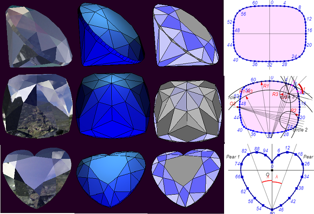
Brilliant . This is the classic and most common diamond cut. Some elements of the construction of a three-dimensional model of this cut are used later in the creation of MoonMarquise, MoonPear and Heart. How the gandist of this super-ellipse-shaped cut is calculated is shown separately in the BrilliantGirdlt.html program. In this program, the girdle line is built on a two-dimensional canvas.
MoonMarquise . The Marquise type cut, as well as Brilliant, is one of the classic cut diamonds. In contrast to the simple cut of this type (Marquise), so-called “moon facets” were added to the MoonMarquise cut on the pavilion. The Moonmarcise cutter is formed by two arcs of ellipses. Detailed construction of this girdle on canvas is shown in the program MarquiseGirdle.html. The text of this program has detailed comments on the construction. Note one point regarding the calculation of the girdle line - it uses the tangent property to the ellipse. It is considered, for example, in the book "The Course of Analytical Geometry" (the author of this book is N.I. Muskhelishvili).
MoonPear . The MoonPear cutter is formed by arcs of three ellipses. Its construction is based on the construction of the Marquise cut girdle, but is more complex. You can see the line of the Marquise girdle and the method of dividing the girdle into segments by launching the program PearGirdle.html.
Heart The heart cut is one of the classic cut-outs, but, unlike most types of cut-outs, it has a non-convex shape of the girdle. The heart-cut rudist is composed of two Pearl boundaries inclined relative to each other. On the canvas you can see the girdle line by running the program HeartGirdle.html. The construction of the Heart cut is a rather complicated task.
Maltese Cross . The round cutter “Maltese cross” is made in the form of a “pillow” (cushion). Cutting with such a girdle has recently become widespread. The line of this girdle consists of eight conjugate arcs of circles - four main arcs bordering the pillow on four sides and four smaller arcs that pair the main arcs of the pillow at the girdle corners. By running the CushionGirdle_1.html and CushionGirdle_2.html programs, you can see the shape of the girdle line, the operation of all parameters defining its shape, and the girdle's division into segments.
Pentagonal Star . The “Pentagonal Star” cutter is formed by a line bearing the name of an epitrochoid. Epitrochoid is a cycloid-related curve. In the program Wavy_Pentagon_Girdle.html, by changing the values of the parameters, you can change the “waviness” of the girdle and even change the pentagon to a polygon with a different number of projections (“petals”). It should however be remembered that the model of this cut itself is built for the value of the parameter “Number of petals” equal to 5.
As mentioned earlier, for all the above models, programs have been created that display the number of vertices of the file. In these programs, a switch is made between the through display of all the model vertices and the display of the number of vertices for the crown, girdle and pavilion separately. Suppose that in the Maltese cut model, you need to create a plane passing through the vertices having the numbers 84, 88 and 145. Instead of creating these planes using the CreatePlaneThreePoints function, you can use these numbers to identify points through which the plane passes the plane using a separate numbering of vertices for girdle and pavilion:
It should be noted that the programs displaying the numbers of the model vertices work very slowly (at least on my computer). It may take a few seconds before the vertex numbers of the model are displayed.
Summarizing all the above, in my opinion, the choice of polyhedra (greenhouse models) for demonstrating the work of geometric functions is one of the best options. Having examined the work of the above examples, you can proceed to the creation of geometric objects belonging to completely different areas of activity than modeling diamond cut.
To display models that were previously calculated using functions from the WebGeometry library, use the ThreeJS library. HTML5 canvas (canvas) is used to display individual flat elements of models and display auxiliary information on the screen.
WebGL technology and libraries created on its basis, such as ThreeJS and BadylonJS, are used on the Internet for realizing a variety of purposes related to 3D graphics. But mostly they are used to display in the browser ready-made three-dimensional models (previously created, for example, in 3ds Max or Blender programs). If we are faced with the task of creating a parametric model, that is, a model in which, in the process of displaying an object in the browser, we can change its individual elements by setting the appropriate model parameters (for example, increase the angle of a certain face), we need to have a set of geometric functions that will allow you to create a model in such a way that in the future it will be possible to interactively vary the shape of individual model elements or the whole model as a whole. To solve this problem, we need a set of functions in the Javascript language, which will implement the methods used in analytical geometry. The library must have functions for creating straight lines, planes and circles, finding points (or straight lines) that intersect them, creating inclined planes, and more. In the ThreeJS and BadylonJS libraries, some of these features are present, but the number of actions performed using them will not allow you to perform all the arising tasks when building a parametric model. There are several other purely mathematical Javascript libraries. Of these, the most widespread are glMatrix and Sylvester . The glMatrix library is mainly designed to work with vectors, matrices, and quaternions, but there are no functions for working with straight lines and planes. The Sylvester library has these functions, but they are present in a rather limited number. However, there are several books in which the implementation of methods of analytic geometry in C / C ++ is described. Corresponding C / C ++ programs can be used as prototypes when creating a Javascript math library. Therefore, when I decided to create three-dimensional parametric models of diamond cut-outs for displaying them in the browser, the library ThreeJS was chosen by me only to display already calculated models on the screen — it was not used to calculate the shape of the models. WebGeometry library was created for the form calculation itself. The basis of this library was taken earlier by the geometric functions I used in C / C ++, which I translated into the Javascript language. Consider the stages of building a model of a pyramid (cut diamond type Pyramid).
')
At the first stage, we need to draw the intended view of the model and then number its vertices. The figure below shows the numbering of the vertices and the names of the cut elements of the pyramid cut model.
After that, it is required to form faces from the numbered vertices. For example, the following sequence of vertices should be written for the face of the site and the edges of the crown (the duplicated first vertex of the face indicates that the face has ended):
0, 3, 2, 1, 0; // 0 - 0, 4, 7, 3, 0, // 1 - 1, 5, 4, 0, 1, // 2 - 2, 6, 5, 1, 2, // 3 - 3, 7, 6, 2, 3, // 4 - Bypassing faces should be counterclockwise. The pyramid_index.js file contains source code for traversing all faces of the pyramid and detailed comments. The result of the traversal is written to the index_cut array.
At the second stage, we can color the faces of the model. This step is optional if we do not need coloring. Suppose we want to color the pyramid model as follows:
For this purpose, a pyramid_colors.js file is created in which the facet_colors () function is located which writes the colors of all faces to the colors array.
At the third stage , after all the vertices are numbered and the sequences of traversing all the vertices of the faces are written, you must set the model parameters and then calculate the coordinates of all its vertices. Of course, it is assumed that we have already outlined a construction algorithm for ourselves and have figured out how all faces of the model will be located in space. For the pyramid, we will select the following parameters, which will set the dimensions of both its individual parts and the model as a whole:
var DEGREE = 0.01745329251994; // var lw = 1.2; // / var r = 0.06; // var angleA = 50*DEGREE; // A var angleB = 60*DEGREE; // B var hCrown = 0.3; // var anglePav = 60*DEGREE; // A The choice of parameters is determined by the model developer. For example, instead of setting two parameters for two corners of the inclination of the crown, you can set a single parameter for two angles at once — then these angles will always be the same. You can enter a parameter that determines the size of the site. In this case, it is necessary either not to set the height of the crown, or not to set the inclination of its faces. Another option for selecting parameters is to make some parameters computable. In this case, when changing some parameters, some others may change their initial value. For example, if we assume that for the pyramid we defined one parameter to set the angle of the crown faces, another parameter for the crown height and another parameter that will define the size of the area, then when we change the inclination of the faces, we will have to change either the size of the area or crown height. On the other hand, if you change the parameter specifying the size of the platform, the value of the parameter specifying either the height or the slope of the crown faces will automatically change. The option associated with the use of calculated parameters in this program, as well as in the construction of the rest of the models, presented on the site, is not used.
At the fourth stage , the coordinates of the model vertices are calculated. The initial data for the calculation are the parameters of the model and how we imagine its appearance. The pyramid_verts.js file contains the source text (with detailed comments) of the model vertex calculation function, which is called VerticesCalculation. It is during this calculation that the functions of the WebGeometry library are used. The results of calculating the coordinates of the vertices are recorded in the array vertices. Note that in the program for finding the coordinates of the vertices, separate sequences of numbers are used for the vertices of the corona (four vertices), the vertices of the girdle (four vertices) and the vertices of the pavilion (in the pyramid model, only the vertex is included in the pyramid). This choice of additional vertex numbering is used for a simpler programmer orientation among the vertices of the cut, since the number of vertices very often exceeds the number 100.
At the fifth stage, after the calculation of the vertex coordinates has been completed, it is required to programmatically construct a polyhedron (polyhedron) of the model. The initial data for its construction are the previously created arrays of index_cut, colors and vertices. A polyhedron model can be represented simply as a set of faces that limit a polyhedron in space. The CreatePolyhedron function is in the polyhedron.js file. As a result of this function, an array of polygons (polygons) of which a three-dimensional model is composed is created. Each polygon is described by the following function (in fact, this constructor function is called by the new operator when creating a new polygon):
function Polygon() { this.IndexFacet = []; // // this.IndexFacet_1 = []; // // this.VertexFacet; // , // this.EdgeFacet = []; // , , // ( // ) this.IndexTriangle = []; // , // , this.VertexTriangle = []; // , // , this.Faces = []; // } Since WebGL and the ThreeJS library created on its basis work with triangular primitives, then for each face of the model its triangulation is performed. It is assumed that all faces of the model are convex polygons. Ultimately, the CreatePolyhedron function takes all the necessary steps to create data structures that fully describe all the faces of a polyhedron in such a way that they can be transferred to the functions of the ThreeJS library to display the model on the screen.
At the sixth stage , the model is displayed on the screen using the ThreeJS functions. The scene, renderer and camera are created in the standard way. In order to inspect the cut pattern from all sides, the Pyramid program uses the orbitControls element. When creating other models of cuts, in order to inspect cuts from all sides, I did not use orbitControls, but introduced the possibility of rotating the model itself. Then we create meshes of the model. You can do in two ways.
In the first method, we consider the faceting model as a set of individual mesh faces. In this case, each face represents a separate 3D object. With this representation of the model, the process of selecting an individual face is quite simply obtained using the Three.JS element, which is called raycaster. Also, this method can be supplemented by creating a mesh of segments bordering each face.
In the second way, we consider the cut model as a single object, represented by just one mesh, including all faces of the model at once. This method is convenient to use when displaying the model using shaders. In the Pyramid cut model, this method is not used, but it is used when creating models of Octagon, Brilliant, and others, which can be seen on my website.
At the seventh stage , buttons and related functions are created that allow you to change the value of the parameters defining the shape and size of the model. When the button is pressed, a function is called that increases or decreases the value of the corresponding parameter. This means that it is necessary to recalculate the coordinate values of the model vertices. After recalculation, the correctness of the newly constructed model is checked. For example, it is determined whether some values are outside the allowable limits. In the case of diamond cut patterns, this usually boils down to checking whether a facet has remained convex after rebuilding it. Check the convexity as follows. Through each face a plane is drawn in which this face lies, and then the position of each vertex of the model relative to that plane is determined. All vertices must be located on the same side of this plane. If the model is recognized as incorrect, then the changed parameter is returned to the original value and the model is rebuilt again. For models of cuts having a non-convex girdle (only this element of some cuts, such as the Heart, may be non-convex), the camber is performed separately for the crown and separately for the pavilion. The gundist is excluded from the check. For simple models, you can restrict yourself to a simple parameter check. For example, if we construct a model of a house, then the roof should not be more than a certain predetermined value in height. Therefore, simply by setting the limit of this parameter in magnitude, we get the desired result. After the parameter buttons are added, it is very desirable to make a visual display of the value of each parameter when it is changed after pressing the button. To do this, create a two-dimensional canvas (canvas) HTML5 and next to the corresponding button on it displays the value of the parameter.
Thus, we considered all the stages of building a model using the example of Pyramid. For the pyramid (as well as for all other models on the site), I created another program Pyramid_text.html. The example of this program shows how you can display three-dimensional text for the numbering of the model vertices. If someone wants to know how complex models are built, then you should consider building models (see GitHub) in the following sequence:
Octagon . A model in which the creation of planes is demonstrated in various ways and working with these planes. When building a model, the methods used when working with vectors and lines in space are also used.
Brilliant . This is the classic and most common diamond cut. Some elements of the construction of a three-dimensional model of this cut are used later in the creation of MoonMarquise, MoonPear and Heart. How the gandist of this super-ellipse-shaped cut is calculated is shown separately in the BrilliantGirdlt.html program. In this program, the girdle line is built on a two-dimensional canvas.
MoonMarquise . The Marquise type cut, as well as Brilliant, is one of the classic cut diamonds. In contrast to the simple cut of this type (Marquise), so-called “moon facets” were added to the MoonMarquise cut on the pavilion. The Moonmarcise cutter is formed by two arcs of ellipses. Detailed construction of this girdle on canvas is shown in the program MarquiseGirdle.html. The text of this program has detailed comments on the construction. Note one point regarding the calculation of the girdle line - it uses the tangent property to the ellipse. It is considered, for example, in the book "The Course of Analytical Geometry" (the author of this book is N.I. Muskhelishvili).
MoonPear . The MoonPear cutter is formed by arcs of three ellipses. Its construction is based on the construction of the Marquise cut girdle, but is more complex. You can see the line of the Marquise girdle and the method of dividing the girdle into segments by launching the program PearGirdle.html.
Heart The heart cut is one of the classic cut-outs, but, unlike most types of cut-outs, it has a non-convex shape of the girdle. The heart-cut rudist is composed of two Pearl boundaries inclined relative to each other. On the canvas you can see the girdle line by running the program HeartGirdle.html. The construction of the Heart cut is a rather complicated task.
Maltese Cross . The round cutter “Maltese cross” is made in the form of a “pillow” (cushion). Cutting with such a girdle has recently become widespread. The line of this girdle consists of eight conjugate arcs of circles - four main arcs bordering the pillow on four sides and four smaller arcs that pair the main arcs of the pillow at the girdle corners. By running the CushionGirdle_1.html and CushionGirdle_2.html programs, you can see the shape of the girdle line, the operation of all parameters defining its shape, and the girdle's division into segments.
Pentagonal Star . The “Pentagonal Star” cutter is formed by a line bearing the name of an epitrochoid. Epitrochoid is a cycloid-related curve. In the program Wavy_Pentagon_Girdle.html, by changing the values of the parameters, you can change the “waviness” of the girdle and even change the pentagon to a polygon with a different number of projections (“petals”). It should however be remembered that the model of this cut itself is built for the value of the parameter “Number of petals” equal to 5.
As mentioned earlier, for all the above models, programs have been created that display the number of vertices of the file. In these programs, a switch is made between the through display of all the model vertices and the display of the number of vertices for the crown, girdle and pavilion separately. Suppose that in the Maltese cut model, you need to create a plane passing through the vertices having the numbers 84, 88 and 145. Instead of creating these planes using the CreatePlaneThreePoints function, you can use these numbers to identify points through which the plane passes the plane using a separate numbering of vertices for girdle and pavilion:
var plane = new Plane3D(); plane.CreatePlaneThreePoints(girdle[68], girdle[72], crown[1]); It should be noted that the programs displaying the numbers of the model vertices work very slowly (at least on my computer). It may take a few seconds before the vertex numbers of the model are displayed.
Summarizing all the above, in my opinion, the choice of polyhedra (greenhouse models) for demonstrating the work of geometric functions is one of the best options. Having examined the work of the above examples, you can proceed to the creation of geometric objects belonging to completely different areas of activity than modeling diamond cut.
Source: https://habr.com/ru/post/418045/
All Articles