Simulation of vibrations and noise in the car's gearbox
In its work, the gearbox used to transfer energy from the engine to the wheels is quite noisy. The first reason for this undesirable effect is that the transverse and axial forces resulting from the transfer of energy from one shaft to another using gear, have an undesirable mechanical effect on the bearings and the housing. The second reason is the flexibility of the various components of the gearbox, including the bearings and housing, which can also lead to vibration. The variable stiffness of the gear clutch in the gearbox causes a constant vibration transmitted to the body, which, in turn, also vibrates and transmits the energy of the surrounding fluid, for example, transmission oil, as a result of which acoustic waves are excited.
To effectively reduce the noise level in such complex dynamic systems in the early stages of design, development engineers often resort to numerical simulation. Under the cut on the example of a 5-speed manual synchronized gearbox, we describe and show the methodology of such research in COMSOL Multiphysics ® , which includes the strength analysis of the mechanical contact of the gearing, the analysis of the dynamics of the multibody gearbox system and the acoustic analysis of the noise generated by the operating box in the surrounding space.

Visualization of sound generated by a working gearbox
Step 1. Calculation of mechanical contact in gearing
The gearing, which we will consider elastic, is a source of constant vibration. For this reason, it is necessary to evaluate the stiffness of the gears in different positions. The teeth are deformed during operation, and a series of stationary strength calculations for various angles of rotation are performed to determine how the stiffness changes during a gear coupling operation cycle. For the calculation, the penalty method is applied to the contact, and constraints are defined to take into account the twisting of the gears, as a result of which contact forces arise.
The characteristic results at the output of such an analysis in the form of the von Mises stress distribution in a gear pair show high stress values at the contact points and at the bases of the teeth (Fig. 1, left). In addition, the calculation made allows us to observe and analyze the change in the rigidity of the gear coupling as the shaft rotates (Fig. 1, right).
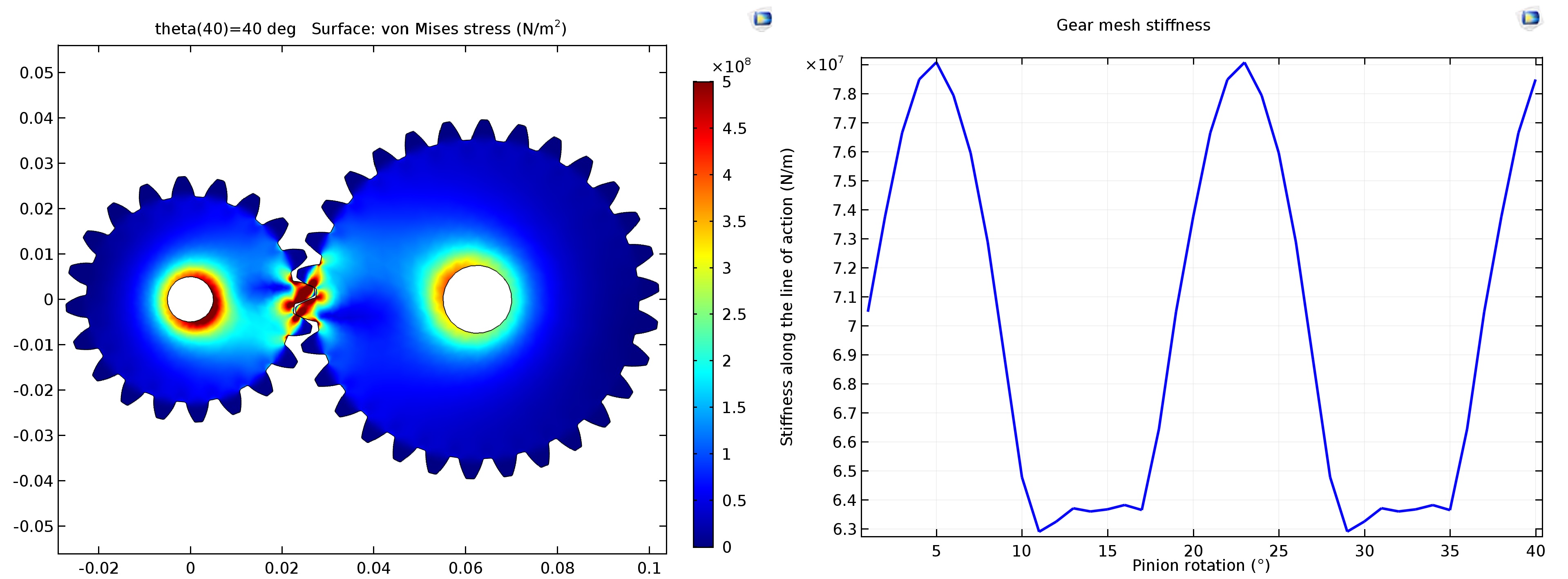
Fig. 1. Left: von Mises stress distribution in a gear pair. Right: change in stiffness of the toothed clutch as the shaft rotates.
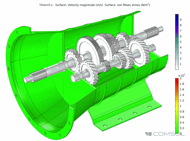
Step 2. Analysis of a multibody system of shafts, gears and casing
Analysis of multibody systems is performed in the time domain for one full rotation of the drive shaft, taking into account the rigidity of the gear coupling, predicted when calculating the contact in the first step. This analysis is necessary to calculate the dynamics of the gears and the values of the resulting vibrations transmitted to the body. In this example, the analysis is performed at an engine speed of 5000 rpm and an output torque of 2000 N m. The calculation is made under the assumption that the shafts and gears are ideally rigid, with the exception of the gear coupling, the rigidity of which is taken from the previous study of mechanical contact. A body made of structural steel is regarded as an elastic body.
The distribution of the von Mises stress in the housing under the action of forces transmitted by the drive and intermediate shafts, as well as the normal acceleration of the vibrating housing, which is the cause of the noise radiation, are shown in Fig. 2

Fig. 2. Left: von Mises stress distribution in the housing. Right: normal acceleration received on the surface of the body.
In fig. 3 shows a time diagram of the normal acceleration in one of the points on the upper part of the body and its frequency spectrum. The frequencies at which the housing vibrates with the greatest amplitude lie in the range between 1500 and 2000 Hz.
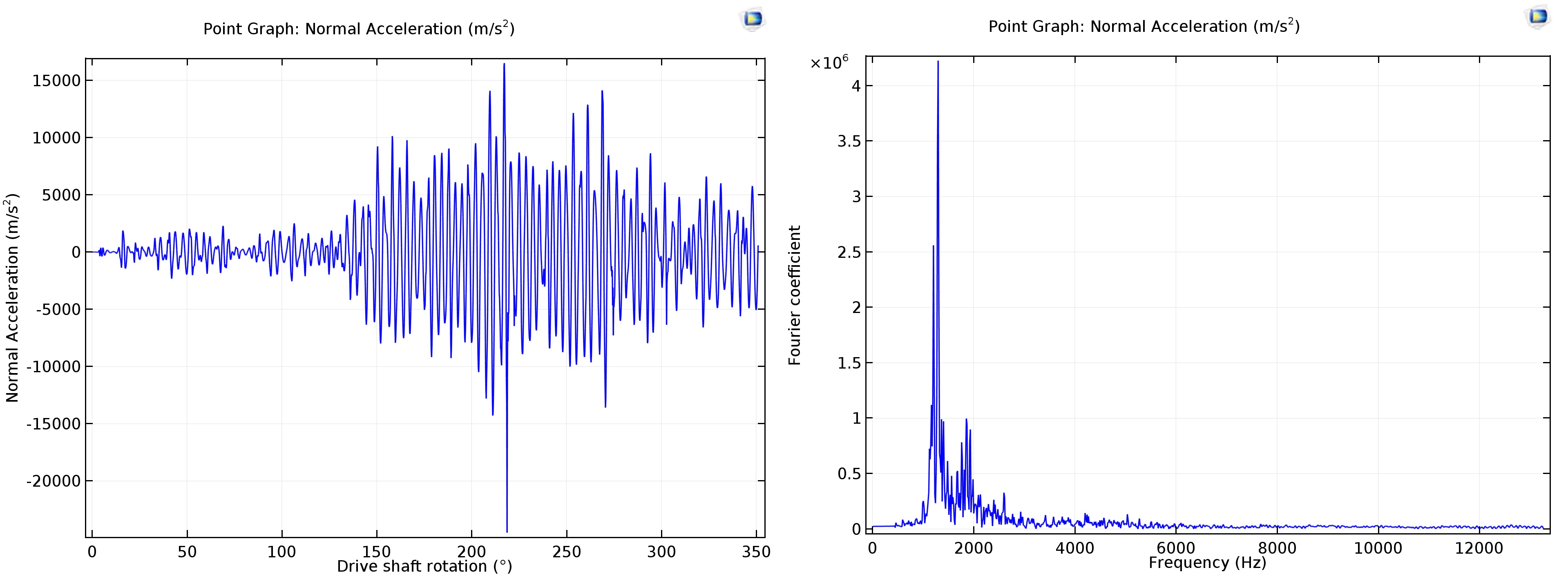
Fig. 3. Normal acceleration at a point on the surface of the body. Left: Timeline. Right: Her frequency spectrum.
Step 3. Acoustic calculation of noise radiation from the body
Normal acceleration of the hull, obtained as a result of analysis of the dynamics of multibody systems, can then be used in acoustic research as a source of noise. Using studies in the frequency domain, one can predict the sound pressure level outside the gearbox. Since the values of normal acceleration are obtained in the time domain, the direct fast Fourier transform (FFT) is used to transform them into the frequency domain. To calculate the acoustic pressure, the gearbox should be surrounded by an air domain, and to reduce the size of the computational domain without reducing the accuracy of the results, a Sommerfeld-type radiation condition for spherical wavefronts is applied to the outer edges of the air region so that outgoing acoustic waves can leave the simulation region with minimal reflection.
The calculation allows to obtain data on the sound pressure level on the surface of the body and in the near zone (Fig. 4), and from the far-field graphs in different planes and at a distance of 1 m, one can find out the prevailing direction of the noise radiation at the selected frequency (Fig. 5).
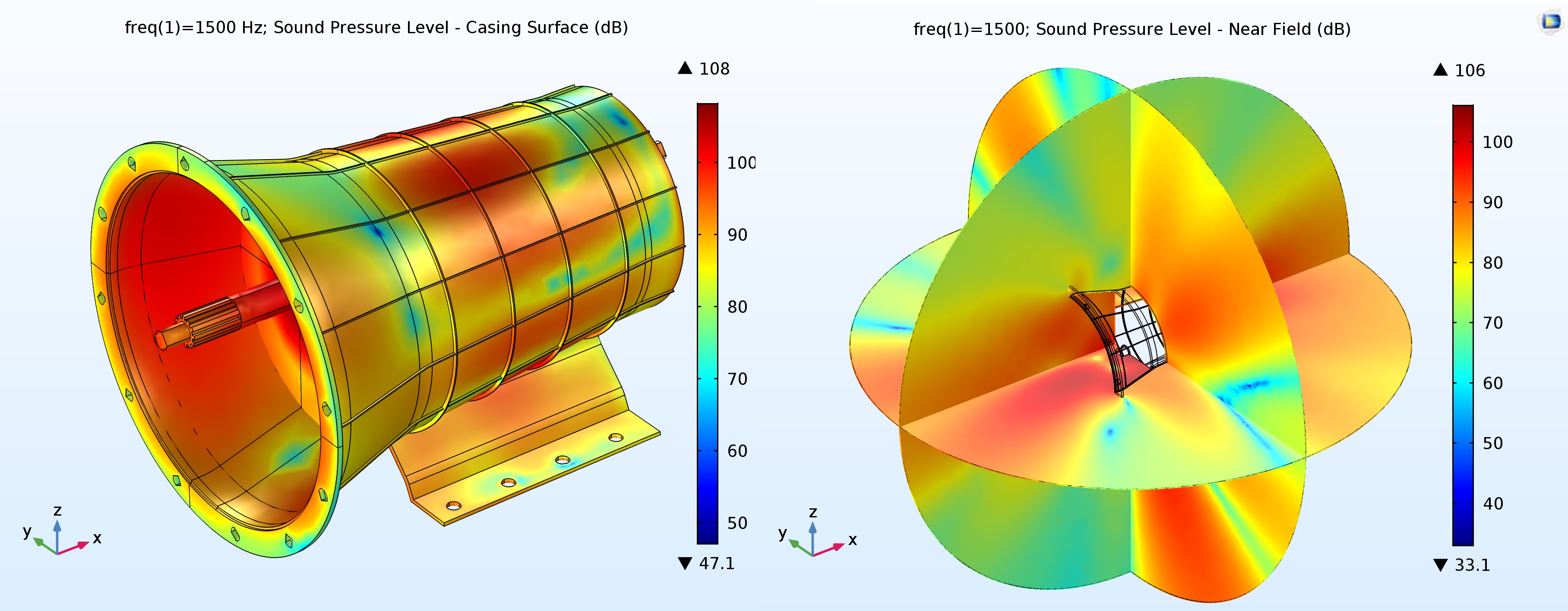
Fig. 4. Sound pressure levels on the surface of the body (left) and in the near zone (right) for the frequency of 1500 Hz.

Fig. 5. The sound pressure level (dB) in the far zone in the xy, xz and yz planes, respectively, at a distance of 1 m for a frequency of 1500 Hz.
Conclusion
In this note, we examined the method of modeling the noise from the gearbox using a combination of mechanical static analysis of a gear coupling, dynamic study of a multibody system and subsequent acoustic calculation.
The actual functionality of the COMSOL Multiphysics ® package will even allow recording and reproducing in the audio format the noise of the gearbox under study , which brings the simulation closer to a real physical experiment.
This technique can be used before the start of the production process to create less noisy gearboxes in the working speed range, as well as in the complex modeling of other working mechanisms in industrial and musical equipment.
Additional Information
This material is based on the following articles:
- Using Software For Gearbox Noise Prediction , Auto Tech Review, June 2017
- How to simulate vibration and noise in a gearbox using COMSOL Multiphysics ® , COMSOL corporate blog
A detailed video tutorial in Russian about assembling models of this class for joint vibration and acoustic analysis of a working gear can be found here . You can also request a demo version of COMSOL in the comments or on our website and independently familiarize yourself with the model described in this note and with step-by-step instructions for assembling it .
More examples of the use of COMSOL ® in acoustic calculations by research teams from B & K, Knowles, ABB, HARMAN and NASA can be found in the issue of COMSOL NEWS 2017: Acoustics in Russian.
- Virtual tuning car audio. HARMAN, France
- Development of industrial and measuring microphones. Bruel & Kjaer, Denmark
- The calculation of the acoustic characteristics of the averaged flow in rocket systems. NASA, USA
- Motorcycle noise reduction. Mahindra Two Wheelers, India
- Investigation of magnetostriction effects and noise in power transformers. ABB, Sweden
- Vibration analysis of the noise generated by the gearbox of the car. COMSOL, USA / Sweden
- Advanced acoustic research of metamaterials. Duke University (USA)
- The effects of vibrations on buildings near airports. NGI, Norway
- Development of hearing aids. Knowles, United States
- Non-destructive acoustic control in water mains. Echologics, Canada
- New design of electrostatic headphones. XI Engineering and WAT, UK
Final gif:
')
Source: https://habr.com/ru/post/417919/
All Articles