Reverse "Neuromant". Part 4: Sound, Animation, Huffman, Github
Hi, as you already understood, this is a continuation of my history of reverse engineering and porting of Neuromant.

Reverse "Neuromant". Part 1: Sprites
Reverse "Neuromant". Part 2: Render the Font
Reverse "Neuromant". Part 3: Finished Rendering, Making the Game
Today we start with two good news:
- Firstly, I am no longer alone - the user viiri has joined the project and has already managed to make a tangible contribution;
- secondly, we now have an open repository on github .
In general, things are going very well and, perhaps, soon we will get at least some playable build. And under the cut, as usual, let's talk about what and how we managed to achieve at the moment.
Began to deal with the sound. Alas, among the game resources there was nothing like audio, and since I had no idea how music works in MS-DOS , it was extremely incomprehensible where to start. After reading a bit about any SoundBlaster , the best I thought of was to scroll the disassembled code in the hope of seeing some familiar signatures. And whoever searches, he usually finds, even if not exactly what he was looking for (comments are stamped by Ida ):
sub_20416: ... mov ax, [si+8] out 42h, al ; 8253-5 (AT: 8254.2). mov al, ah out 42h, al ; Timer 8253-5 (AT: 8254.2). mov bx, [si+0Ah] and bl, 3 in al, 61h ; PC/XT PPI port B bits: ; 0: Tmr 2 gate ═╦═► OR 03H=spkr ON ; 1: Tmr 2 data ═╝ AND 0fcH=spkr OFF ; 3: 1=read high switches ; 4: 0=enable RAM parity checking ; 5: 0=enable I/O channel check ; 6: 0=hold keyboard clock low ; 7: 0=enable kbrd and al, 0FCh or al, bl out 61h, al ; PC/XT PPI port B bits: ; 0: Tmr 2 gate ═╦═► OR 03H=spkr ON ; 1: Tmr 2 data ═╝ AND 0fcH=spkr OFF ; 3: 1=read high switches ; 4: 0=enable RAM parity checking ; 5: 0=enable I/O channel check ; 6: 0=hold keyboard clock low ; 7: 0=enable kbrd Googling this Timer 8253-5 I came across an article that became the first key to understanding what was happening. Below I will try to explain what's what.
So, in the era of IBM-PC , before the availability of sound cards, the most common audio playback device was the so-called PC Speaker , also known as "beeper." This device is nothing more than a normal speaker, connected to the motherboard, in most cases, through a four-pin connector. Beeper, as planned, allowed to reproduce a two-level rectangular pulse (corresponding to two voltage levels, usually 0V and + 5V) and was controlled via the 61st port of the PPI controller (Programmable Peripheral Interface) . Specifically, the first two bits of the value sent to the port are responsible for controlling the “speaker” (see comments to the strings in al, 61h and out 61h, al ).
As I said (in a few other words), our speaker can be in two states - “in” and “out” ( “low” - “high” , “off” - “on” , “off” - “on” , as you wish). To create a single pulse, you need to change the current state to the opposite and, after some time, back. This can be done directly by manipulating the first bit (counting from scratch) of port 61, for example, like this:
PULSE: in al, 61h ; and al, 11111100b ; ... or al, 00000010b ; ... ; , 0 out 61h, al ; 61- mov cx, 100 ; DELAY: loop DELAY ; in al, 61h ; and al, 11111100b ; out 61h, al ; 61- The result of the execution of this code will look as follows:
loop DELAY +5V +----------------------+ ! ! 0V ---+ +-------------------------- or al, 00000010b and al, 11111100b out 61h, al out 61h, al Repeating PULSE with a delay, we get a square wave:
mov dx, 100 ; 100 PULSE: ... mov cx, 100 WAIT: loop WAIT dec dx jnz PULSE PULSE +5V +---------+ +---------+ +---------+ ! ! ! ! ! ! 0V ---+ +---------+ +---------+ +--- loop WAIT If in the first case we would hardly have heard something, then in the second we will get a tone of frequency depending on the speed of the machine at which this code is executed. This is great, but it is associated with certain difficulties. In any case, there is a more convenient way to control the speaker.
Here a programmable three-channel timer comes into play - the Intel 8253 , the second channel of which (starting from zero) is connected to the beeper. This timer receives a signal from the Intel 8254 clock chip, sending 1193180 pulses per second (~ 1.193 MHz), and can be programmed for a specific reaction after the specified number of pulses. One of these reactions is sending a square pulse to a speaker. In other words, the 8253 can operate in the mode of a rectangular signal generator with an adjustable frequency; this makes it relatively easy to synthesize various sound effects on a speaker. And here's what you need to do:
- Set the second channel of the timer to generate a square wave. To do this, write a special single-byte value to port 43 ( 8253 Mode / Command register ). In my case, this is
10110110B(more10110110Bhere ):
Bits Usage 6 and 7 Select channel : 1 0 = Channel 2 4 and 5 Access mode : 1 1 = Access mode: lobyte/hibyte 1 to 3 Operating mode : 0 1 1 = Mode 3 (square wave generator) 0 BCD/Binary mode: 0 = 16-bit binary Set the desired frequency on the second channel. To do this, byte-by-byte, from low to high, we send to the 42nd port ( 8253 Channel 2 data port ) a value of
1193180 / freq, wherefreqis the required frequency value in Hertz.Allow the speaker to receive impulses from the timer. To do this, set to the first two bits of the value in port 61 ( PPI ). The fact is that if the zero bit is set to 1, then the first is interpreted as a “switch”:
Bit 0 Effect ----------------------------------------------------------------- 0 The state of the speaker will follow bit 1 of port 61h 1 The speaker will be connected to PIT channel 2, bit 1 is used as switch ie 0 = not connected, 1 = connected. As a result, we have the following picture:
mov al, 10110110b out 43h, al ; mov ax, 02E9Bh ; 1193180 / 100 = ~0x2E9B out 42h, al ; mov al, ah out 42h, al ; in al, 61h ; or al, 00000011b ; 1 out 61h, al ; ... ; ~100 in al, 61h and al, 11111100b out 61h, al ; And this is exactly what the code I did at the very beginning does (except for initialization, but I found it in another function): at si + 8 there is a frequency divider sent to port 42, and at si + 0Ah - the state of the speaker ( "on" - "off" ), recorded in port 61.
The playback mechanism is simple and clear, but then it was necessary to deal with the timings. Having studied the nearby code, I saw that in the same function in which the timer is initialized ( sub_2037A , then - init_8253 ), the eighth interrupt handler ( Time of Day ) is sub_20416 function (hereafter - play_sample ). It soon became clear that this interrupt is generated approximately 18.2 times per second and serves to update the system time. Replacing this interrupt handler is a common practice if you need to perform some action 18 times per second (in fact, you must also call the original handler inside the hook, otherwise the system time will stop). Based on this, it turns out that the next frequency is charged to the generator every (1 / 18.2) * 1000 ~ 55 .
The plan was:
- put a breakpoint in the
play_samplefunction, on the line where the next frequency divider is extracted; - calculate the frequency using the formula
freq = 1193180 / divisor; - generate 55ms of freq square wave signal in some audio editor (I used Adobe Audition );
- repeat the first three steps to accumulate at least 3 seconds.
So I got the beginning of the melody from the main menu, but playing times 10 times slower than necessary. Then I shortened the sample duration from 55 ms to 5 ms - it became much better, but still not that. The issue with timings remained open until I found this article . It turned out that the eighth interrupt is generated from the filing of the same 8253 , the zero channel of which is connected to the interrupt controller ( PIC ). During machine boot, the BIOS sets the zero channel to generate pulses with a frequency of ~ 18.2 Hz (that is, an interrupt is generated every ~ 54.9 ms). However, the zero channel can be reprogrammed so that it generates pulses with a higher frequency. To do this, by analogy with the second channel, the 40th port needs to write a value equal to 1193180 / freq , where freq is the required frequency value in Hertz. This is what happens in the function init_8253 , just initially I did not pay enough attention to this:
init_8253: ... mov al, 0B6h ; 10110110b out 43h, al ; Timer 8253-5 (AT: 8254.2). mov ax, 13B1h out 40h, al ; Timer 8253-5 (AT: 8254.2). mov al, ah out 40h, al ; Timer 8253-5 (AT: 8254.2). 13B1h translate the 13B1h value into the frequency: 1193180 / 13B1h ~ 236.7 , then we get approximately (1 / 236.7) * 1000 ~ 4.2 to the “sample”. The puzzle has developed.
Next is the case of technology - to implement a function that extracts sound tracks from the game. But here's the thing, the values of frequency dividers recorded in the 42nd port are not stored explicitly. They are calculated by a certain cunning algorithm, the input data and the working area of which lie directly in the executable file of the game (in the seventh segment according to Ida ). Also, among the features, there is no indication of the end of the track, when there is nothing more to play, the algorithm infinitely produces the zero state of the speaker. But I did not bother, and, as in the case of the decompression algorithm ( first part ), I simply ported to 64-bit assembler the function of setting the track for playback and the algorithm for obtaining the next frequency (I took the seventh segment as a whole).
And it worked. After that, I implemented the soundtrack generation functions for the selected track ( PCM, 44100 Hz, 8 bit, mono ; I did something like a generator used in a speaker emulator in DosBox ). I solved the problem with the termination sign with a simple silence counter: counted a second — we complete the algorithm. Wrapping the resulting track into a WAV header, and saving the result to a file, I got exactly the track from the main menu. And 13 more tracks that you can listen to below [or in the resource viewer, which now has a built-in player and the ability to save any track to .WAV] :
[Studying the question, I also learned about the more advanced “beeper playing” techniques, such as using pulse-width modulation for low-quality PCM audio playback. At the end of this article I will give a list of materials from which you can learn more.]
In the second part , when different resource formats were considered, I assumed that in .ANH files there are animations for backgrounds of locations (that is, for images stored in .PIC ). [This is so.] Having finished with the sound, I decided to check it out. Purely based on the assumption that the animation is applied directly to the image of the backdrop stored in memory (not in video memory , but in sprite-chain ), I decided to make dumps of this memory, respectively, before and after applying the animation (look where the cursor points - at the top the string of the letter 'S'):

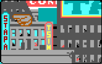
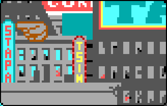
3DE6:0E26 03 B4 44 B3 ... ; 3DE6:0E26 03 BC CC B3 ... ; Exactly what I expected - dark red color (0x4) changed to bright red (0xC). Now you can try to set a breakpoint to change the value at the address, for example, 3DE6:0E28 and, if you're lucky, do a reverse trace. [I was lucky.] The breakpoint led me to a line that directly changes the value at a given address: xor es:[bx], al . After examining the surroundings, I easily built a chain of calls from the main loop of the level up to this point: sub_1231E (xor es:[bx], al) <- sub_12222 <- sub_105F6 <- sub_1038F ( ) .
I will not go into details about how I reverse the animation process. This is a fairly routine and methodical work, but not very difficult if the boundaries are clearly defined (the backtrack obtained is these boundaries). But I can not tell you about what happened in the end.
First about the .ANH format. In fact, it is a set of containers, and the first word in the .ANH file is the number of containers inside:
typedef struct anh_hdr_t { uint16_t anh_entries; /* first entry hdr */ } anh_hdr_t; By itself, a container is a separately taken animation of the background element. The container can have a header that contains its byte size and the number of frames in the animation it represents. Following the header, the duration (delay) of the next frame and the byte offset of the frame itself, relative to the bytes of the first frame, go in pairs. The number of such pairs is obviously equal to the number of frames:
typedef struct anh_entry_hdr_t { uint16_t entry_size; uint16_t total_frames; /* anh_frame_data_t first_frame_data */ /* another frames data */ /* anh_frame_hdr first_frame_hdr */ /* another frames */ } anh_entry_hdr_t; typedef struct anh_frame_data_t { uint16_t frame_sleep; uint16_t frame_offset; } anh_frame_data_t; ... extern uint8_t *anh; anh_hdr_t *hdr = (anh_hdr_t*)anh; anh_entry_hdr_t *entry = (anh_entry_hdr_t*)(anh + sizeof(anh_hdr_t)); for (uint16_t u = 0; u < anh->anh_entries; u++) { uint8_t *p = (uint8_t*)entry; anh_frame_data_t *first_frame_data = (anh_frame_data_t*)(p + sizeof(anh_entry_hdr_t)); uint8_t *first_frame_bytes = p + (entry->total_frames * sizeof(anh_frame_data_t)); for (uint16_t k = 0; k < entry->total_frames; k++) { anh_frame_data_t *frame_data = first_frame_data + k; uint8_t *frame_bytes = first_frame_bytes + frame_data->frame_offset; ... } /* plus 2 bytes of padding */ p += (entry->entry_size + 2); entry = (anh_entry_hdr_t*)p; } A separate frame consists of a four-byte header containing its linear dimensions and displacements relative to the background image, and frame pixels encoded by the Run Length algorithm I already know:
typedef struct anh_frame_hdr { uint8_t bg_x_offt; uint8_t bg_y_offt; uint8_t frame_width; uint8_t frame_height; /* rle encoded frame bytes */ }; "Overlay" frame on the backdrop may look like this:
extern uint8_t *level_bg; uint8_t frame_pix[8192]; anh_frame_hdr *hdr = (anh_frame_hdr*)frame_bytes; uint16_t frame_len = hdr->frame_width * hdr->frame_height; decode_rle(frame + sizeof(anh_frame_hdr), frame_len, frame_pix); /* 0xFB4E - some magic value, have no idea what is it */ uint16_t bg_offt = (hdr->bg_y_offt * 152) + hdr->bg_x_offt + 0xFB4E; uint16_t bg_skip = 152 - hdr->frame_width; uint8_t *p1 = frame_pix, *p2 = level_bg; for (uint16_t i = hdr->frame_height; i != 0; i--) { for (uint16_t j = hdr->frame_width; j != 0; j--) { *p2++ ^= *p1++; } p2 += bg_skip; } This is the .ANH format , but there is another structure that makes it all work:
typedef struct bg_animation_control_table_t { uint16_t total_frames; uint8_t *first_frame_data; uint8_t *first_frame_bytes; uint16_t sleep; uint16_t curr_frame; } bg_animation_control_table_t; In the game itself, an array of at least four structures of this type is globally declared. After loading the next .ANH file, the number of animations inside is also saved to the global variable, and the array elements are initialized as follows:
extern uint8_t *anh; uint16_t g_anim_amount = 0; bg_animation_control_table_t g_anim_ctl[4]; ... anh_hdr_t *hdr = (anh_hdr_t*)anh; anh_entry_hdr_t *entry = (anh_entry_hdr_t*)(anh + sizeof(anh_hdr_t)); g_anim_amount = hdr->anh_entries; for (uint16_t u = 0; u < g_anim_amount; u++) { uint8_t *p = (uint8_t*)entry; g_anim_ctl[u].total_frames = entry->total_frames; g_anim_ctl[u].first_frame_data = p + sizeof(anh_entry_hdr_t); g_anim_ctl[u].first_frame_bytes = g_anim_ctl[u].first_frame_data + (entry->total_frames * sizeof(anh_frame_data_t)); g_anim_ctl[u].sleep = *(uint16_t*)(g_animation_control[u].first_frame_data); g_anim_ctl[u].curr_frame = 0; /* plus 2 bytes of padding */ p += (entry->entry_size + 2); entry = (anh_entry_hdr_t*)p; } Finally, apply animations:
for (uint16_t u = 0; u < g_anim_amount; u++) { bg_animation_control_table_t *anim = &g_anim_ctl[u]; if (anim->sleep-- == 0) { anh_frame_data_t *data = (anh_frame_data_t*)anim->first_frame_data + anim->curr_frame; /* */ ... if (++anim->curr_frame == anim->total_frames) { anim->curr_frame = 0; data = (anh_frame_data_t*)anim->first_frame_data; } else { data++; } anim->sleep = data->frame_sleep; } } And we get the following [much more can be viewed in the resource viewer] :
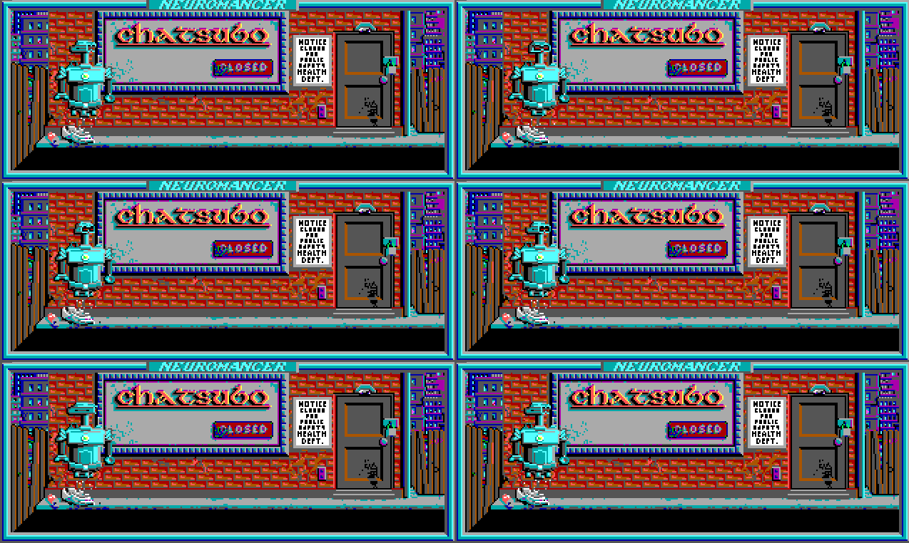

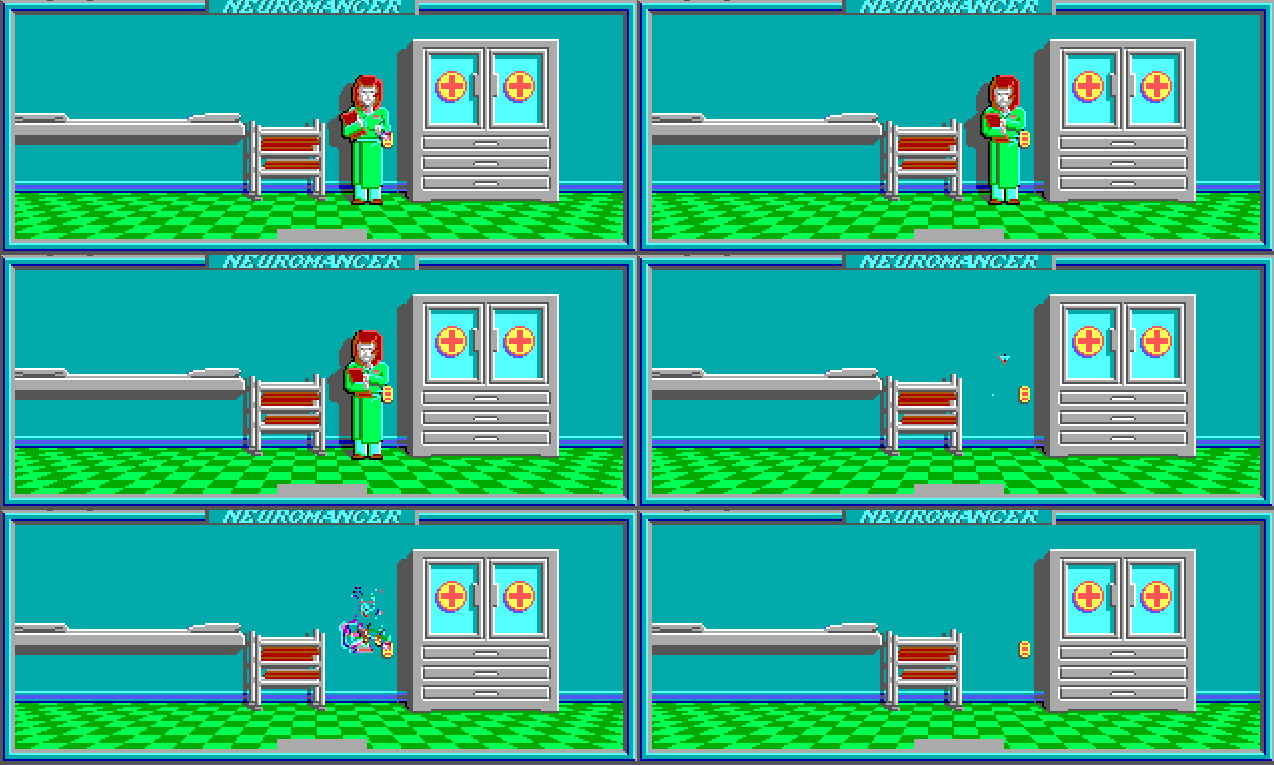
There are a couple of problems with animation at the moment. The first is that in my code I play all the available animations, but the original checks for some global flags, indicating whether to scroll through the next one. And the second, due to the fact that some animations add objects to the screen that are not there initially. And since the frames are “citing” on the background, then with cyclic scrolling, the object simply disappears on every second lap. Here, for example, how it might look like:
But for now, let's leave it at that.
Remember the unknown decompression algorithm from the first part ? Having barely connected to the development, viiri not only determined what kind of algorithm it was, but also wrote his own version of the decoder, replacing the awful three-lined piece of Assembler in the codebase. In this regard, I asked viiri to write a short essay on the work done. What was done, but before I give it, a few words need to be said about the theory.
To compress resources, Neuromant developers used Huffman code . This is one of the first effective methods for encoding information using prefix codes . In coding theory, prefix codes are codes with a word of variable length and those in which no code word is a prefix of another. That is, if the word “a” is part of the prefix code, then the word “ab” does not exist in the code. This property allows you to uniquely break into words the message encoded by such code.
The idea of the Huffman algorithm is that, knowing the probabilities of the appearance of symbols of a certain alphabet in a message, one can describe the procedure for constructing codes of variable length, consisting of an integer number of bits. Characters with a higher probability of occurrence are assigned shorter codes, while characters with a lower probability are, on the contrary, longer codes. In general, the coding procedure is reduced to the construction of an optimal code tree and, based on it, the mapping of the message symbol to the corresponding code. The prefix property of the resulting code allows you to uniquely decode the compressed message.
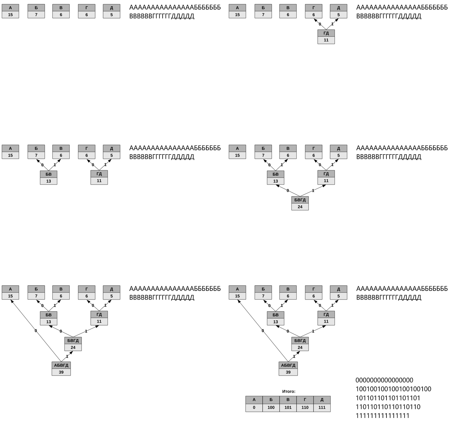
The algorithm has one major drawback (in fact, not one, but now only this one is important). The fact is that in order to restore the contents of a compressed message, the decoder must know the table of frequency of appearance of characters used by the encoder. In this regard, together with the encoded message, either the probability table or the code tree itself must be transmitted (the variant used in the game). The size of the additional data can be relatively large, and this significantly increases the compression efficiency.
Something about how to deal with this, as well as about your decoder and the one that is implemented in the game, tells viiri :
Immediately it is worth mentioning that the whole game was completely written in Assembler, by hand, so the code contains interesting solutions, tricks and optimizations.
According to the procedures. Thesub_1ff94(build_code_table) function is needed to load a Huffman tree from a file. To decode a static Huffman (sometimes a dynamic one , and this requirement does not apply to it), along with the message, you must pass a code tree, which is the mapping of Huffman codes to real character codes. This tree is big enough and therefore it would be nice to store it somehow. The most correct way is to use canonical codes ( MOAR ). Due to their properties, there is a very interesting and efficient way to store a tree (used in the implementation of the Deflate compression method of the archiver PKZip ). But in the game, canonical codes are not used, instead a direct traversal of the tree is performed and for each vertex bit 0 is written to the output stream if the node is not a leaf, or bit 1 if the node is a leaf, then the next 8 bits are the character code in this the node. When decoding a similar traversal of the tree, which we see in the game. There is an example and some explanation.
build_code_table proc near call getbit ; jb short loc_1FFA9 ; ... shl dx, 1 inc bx call build_code_table ; build_code_table or dl, 1 call build_code_table ; build_code_table shr dx, 1 dec bx ret loc_1FFA9: call sub_1FFC2 ; (8 ) ... ; ret sub_1FF94 endp sub_1FFC2 proc near sub di, di mov ch, 8 loc_1FFC6: call getbit rcl di, 1 dec ch jnz short loc_1FFC6 retn sub_1FFC2 endp getbit(sub_1ffd0) reads a bit from the input stream. Her analysis allows us to conclude that the individual bits are allocated from the 16-bit registerax, the value of which is loaded from memory with thelodswinstruction, which loads two bytes from the stream, but since the Intel processor is in little-endian byte order,xchghalf of the register. Further, the order of bits in the stream looks somewhat illogical - the first is not the youngest, but the high bit. ,shl,jb.
getbit proc near or cl, cl jz short loc_1FFD9 dec cl shl ax, 1 retn loc_1FFD9: cmp si, 27B6h jz short loc_1FFE7 ; lodsw xchg al, ah mov cl, 0Fh shl ax, 1 retn loc_1FFE7: call sub_202FC ; lodsw xchg al, ah mov cl, 0Fh shl ax, 1 retn getbit endp viiri , :
typedef struct node_t { uint8_t value; struct node_t *left, *right; } node_t; static uint8_t *g_src = NULL; static int getbits(int numbits) { ... } static uint32_t getl_le() { /* 4- */ } static node_t* build_tree(void) { node_t *node = (node_t*)calloc(1, sizeof(node_t)); if (getbits(1)) { node->right = NULL; node->left = NULL; node->value = getbits(8); } else { node->right = build_tree(); node->left = build_tree(); node->value = 0; } return node; } int huffman_decompress(uint8_t *src, uint8_t *dst) { int length, i = 0; node_t *root, *node; g_src = src; length = getl_le(); node = root = build_tree(); while (i < length) { node = getbits(1) ? node->left : node->right; if (!node->left) { dst[i++] = node->value; node = root; } } ... } :
build_code_table. , , . , . , , , — (huffman_decompress).
? Right! ! , . ( ): . , 3- , N , (3 — N) .
ABCD : A - 0b, B - 10b, C - 110b, D - 111b . ( ), , :
| Code | Length | Symbol |
|---|---|---|
| 0 00b | one | A |
| 10 0b | 2 | B |
| 110 b | 3 | C |
| 111 b | 3 | D |
, . , , , 010b — . . , 'A' 0b , , . :
| Index | Code | Length | Symbol |
|---|---|---|---|
| 0 | 0 00b | one | A |
| one | 0 01b | one | A |
| 2 | 0 10b | one | A |
| 3 | 0 11b | one | A |
| four | 10 0b | 2 | B |
| five | 10 1b | 2 | B |
| 6 | 110 b | 3 | C |
| 7 | 111 b | 3 | D |
, 011010111b :
- :
011b; - ,
011b (3),A, ; 011b1, , :110b;- ,
110b (6),, ; - , .
«» 8- . 256 . 8 . , , :
: — , . , . 4 — 32- .
, . .
, github . , , , - [ , README.md] .
, , 2015- :
- LibNeuroRoutines (, MASM) — , , . (
neuro_routines.h) , . , :- (
huffman_decompression.c,decompression.c); - (
cp437.c); - (
dialog.c); - (
audio.c).
- (
- NeuromancerWin64 () — . . , «» , , . CSFML ( SFML C ).
- ResourceBrowser (C++) — . MFC -, .DAT -. :
- BMP (8bpp) ( IMH , PIC );
- ( ANH );
- WAV (PCM, 44100Hz, 8bps, mono) ( SOUND ).
LibNeuroRoutines . LibNeuroRoutines CSFML ( ResourceBrowser SFML ).
64- Windows . , LibNeuroRoutines 64- MASM (Microsoft Macro Assembler) . — , 64- . , NASM FASM , , . VS 2015 — MASM .
, . C . , ( , MFC ).
, . - , .
. ? , . , . - , . , , , . ().
')
Source: https://habr.com/ru/post/417639/
All Articles