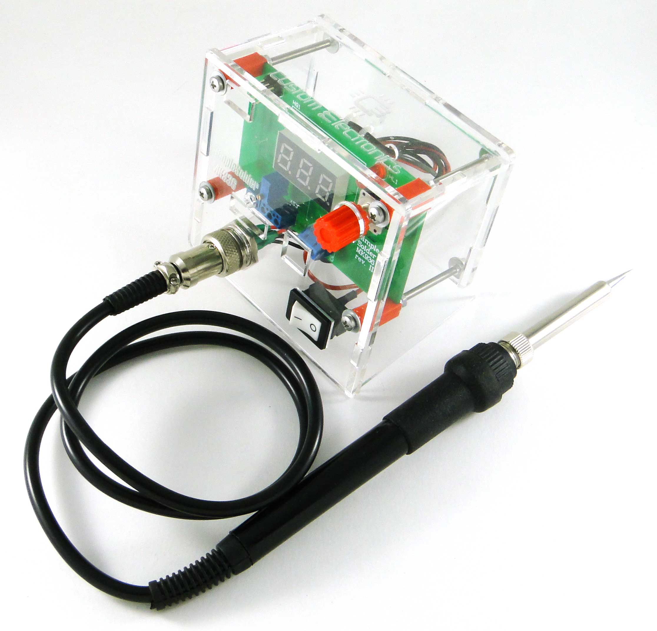
Simple Solder MK936 SMD. DIY soldering station on SMD components
In this article we want to introduce you to the project of a soldering station, which everyone can assemble with their own hands.
It represents a soldering iron with a unit for setting and adjusting the temperature. In the article you will find diagrams, circuit boards drawings, firmware for the microcontroller, as well as recommendations for assembly and configuration.
Having collected it, you will gain experience with components of surface mounting (SMD) and, of course, a useful device.
')
The soldering station differs from a simple network soldering iron in that it has temperature stabilization. And it is very important when working with various trifles. Network soldering iron always dissipates the same power. That is, if it lies on the spot, it can even heat up to 500 degrees, and when you begin to solder, it sharply cools.
On the other hand, if a thermocouple is built into the soldering iron, you can arrange feedback. This makes it possible to regulate the power on the heater in order to maintain a stable temperature.
Our goal was to develop a soldering station based on a common and cheap soldering iron with a thermocouple. It has the following characteristics:
The board is double-sided, but adapted for manufacturing at home. At the end of the article you will find a link to the file for SprintLayout.

If you are interested in the scheme of the device, you can find it here . On it, only the reference designations of the elements and the pin numbers of the microcontroller differ. In fact, everything is done on the Atmega8 microcontroller, to which a seven-segment indicator, an encoder, a heater through a switch and a signal from a thermocouple, amplified by an operational amplifier, are connected.
The following components and materials will be required to assemble the circuit board and case:
Here is a set of all the details:
When assembling it is convenient to use assembly drawings:


You need to start with the installation of SMD components. Install elements on the board according to the list of elements. When installing elements, it is important to follow the orientation of the tantalum capacitors and the operational amplifier. The first output of DA2 is determined by the bevel on the body.
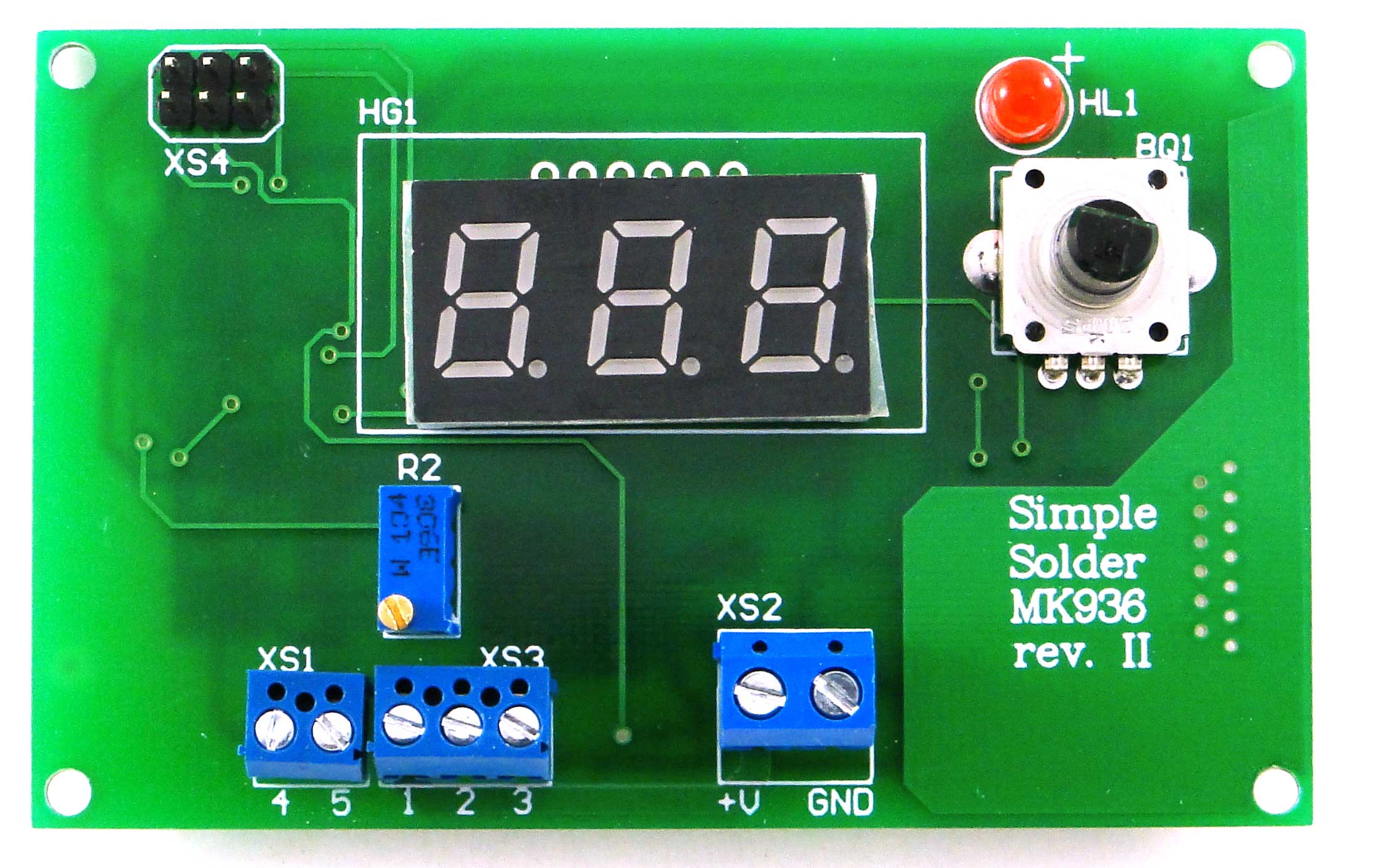
If everything is assembled correctly, the board should look like this.
Please note that we used 1kOhm resistors without marking.
Next, you need to install the output elements on the board in accordance with the list of elements. Long LED output is a plus. The seven-segment indicator is set “points” down.
Here is the front side of the PCB assembly:
Power and soldering iron are connected according to the following scheme:

Before assembling the case, it is necessary to prepare a switch and a connector. The switch must be connected to the break of the red wire so that on one contact of the switch there is a short piece of red thick wire, and on the second a long one.
You need to connect short red wires to the first and fifth pins of the soldering iron connector, and the rest to black.
Heat-shrink tubing should be worn on the switch and the connector and tinned all the free ends of the wires, so that later it was more convenient to fasten them to the terminals.
Next, you need to install a switch and a soldering iron connector on the front panel. Please note that the switch may be installed tightly and it may be necessary to modify the slot for it with a file.
Then you should connect the first pin of the connector to the first pin of the board, the second to the second, and so on. in accordance with the above figure. The power supply on the board must be connected to the red short wire from the switch, and to the minus the black wire.

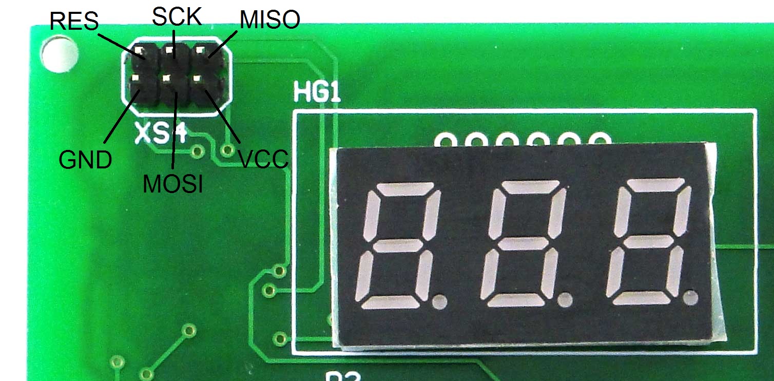
In the upper left corner of the board there is a standard ISP connector for flashing AVR microcontrollers.
You can flash the microcontroller with any programmer you have, for example USBasp. If the programmer provides power itself supplies 5V, then connect the external is not required. You can also find the firmware file at the end of the article.
Configuration bits! You must enable CKSEL0, CKSEL2, CKSEL3, SUT0, BOOTSZ0, BOOTSZ1 and SPIEN! That is, a change of default settings is required to start the controller at a clock frequency of 2 MHz.
Now you can connect a soldering iron and supply the input supply voltage (from 12 to 24V). After switching on, the soldering iron should start to heat up, and the temperature reading on the indicator should increase. When the encoder shaft rotates, the value of the required temperature should change.
Now you can screw the board to the front panel. It is allowed to use conventional racks with a height of 10 mm, but we have prepared special racks that provide better fixation of the board. A model for 3D printing can also be found at the end of the article.
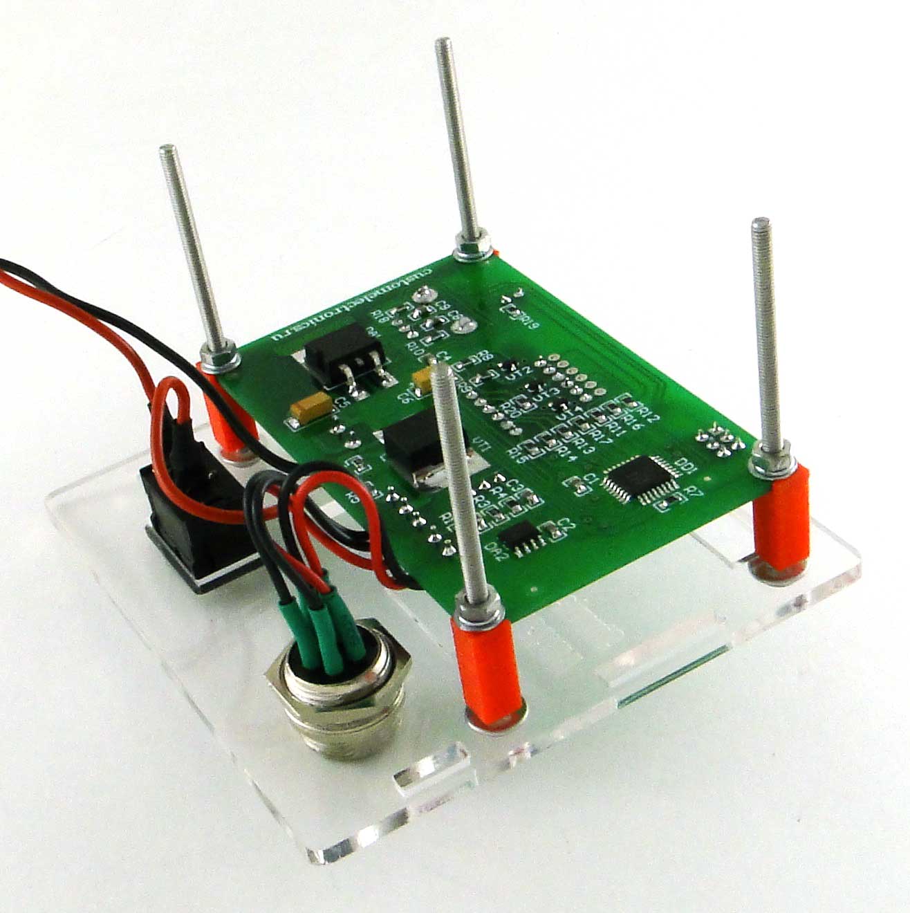
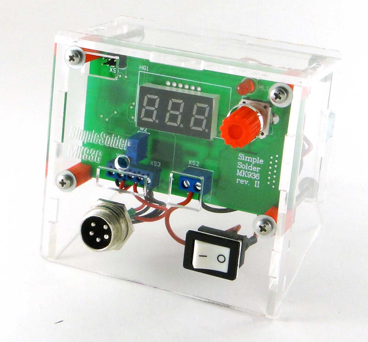
Side walls are installed without any mounts. Now it remains only to insert the rear cover into the grooves, tighten the nuts, pull the power wires through the hole and fix them with cable clamps. Remember that the plexiglass parts are quite fragile and do not overtighten the fasteners!

For precise temperature adjustment using a trimmer resistor. The front panel has a special opening for access to it.
When calibrating, first of all it is necessary to bring the sting to the temperature at which the solder melts. You can just set the encoder very high temperature immediately. Then, having collected a solder ball on a sting, it is required to warm up the thermocouple. There are special measuring devices for such purposes, but an ordinary multimeter with a thermocouple will do. Next, by rotating the trimming shaft, ensure that the measured value of the soldering station matches the readings of the external thermocouple.
During calibration, remember that the more time you give a soldering iron to stabilize the temperature, the more accurately you will be able to adjust it. Also note that the trimmer is multi-loop and one revolution changes the temperature very slightly. That is, you need to turn it boldly and a lot.
We also prepared a video instruction:
Direct links to all the necessary files for downloading can be found on the main page of the project .
This device also has a version on a one-sided board using only pin components. Find it here
Once again I want to emphasize that we provide all the necessary and very detailed information for the independent production of this device, and additionally we provide the opportunity to purchase it in the form of a set ( one , two , three ).
PS: and we are also preparing a hairdryer) thanks for your interest in our activities!
It represents a soldering iron with a unit for setting and adjusting the temperature. In the article you will find diagrams, circuit boards drawings, firmware for the microcontroller, as well as recommendations for assembly and configuration.
Having collected it, you will gain experience with components of surface mounting (SMD) and, of course, a useful device.
')
Description
The soldering station differs from a simple network soldering iron in that it has temperature stabilization. And it is very important when working with various trifles. Network soldering iron always dissipates the same power. That is, if it lies on the spot, it can even heat up to 500 degrees, and when you begin to solder, it sharply cools.
On the other hand, if a thermocouple is built into the soldering iron, you can arrange feedback. This makes it possible to regulate the power on the heater in order to maintain a stable temperature.
Our goal was to develop a soldering station based on a common and cheap soldering iron with a thermocouple. It has the following characteristics:
- Powered by a DC voltage source of 12-24V
- Power consumption, with 24V power: 50W
- Soldering iron resistance: 12Ω
- Time of an exit to an operating mode: 1-2 minutes depending on the feeding tension
- Maximum deviation of temperature in the stabilization mode, not more than 5 degrees
- Regulation algorithm: PID
- Temperature display on a seven-segment display
- Heater type: nichrome
- Type of temperature sensor: thermocouple
- Temperature calibration capability
- Temperature setting with encoder
- LED to display the status of the soldering iron (heating / work)
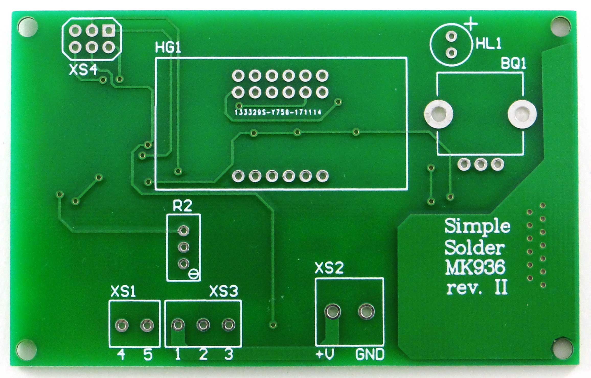
Printed circuit board
The board is double-sided, but adapted for manufacturing at home. At the end of the article you will find a link to the file for SprintLayout.
If you are interested in the scheme of the device, you can find it here . On it, only the reference designations of the elements and the pin numbers of the microcontroller differ. In fact, everything is done on the Atmega8 microcontroller, to which a seven-segment indicator, an encoder, a heater through a switch and a signal from a thermocouple, amplified by an operational amplifier, are connected.
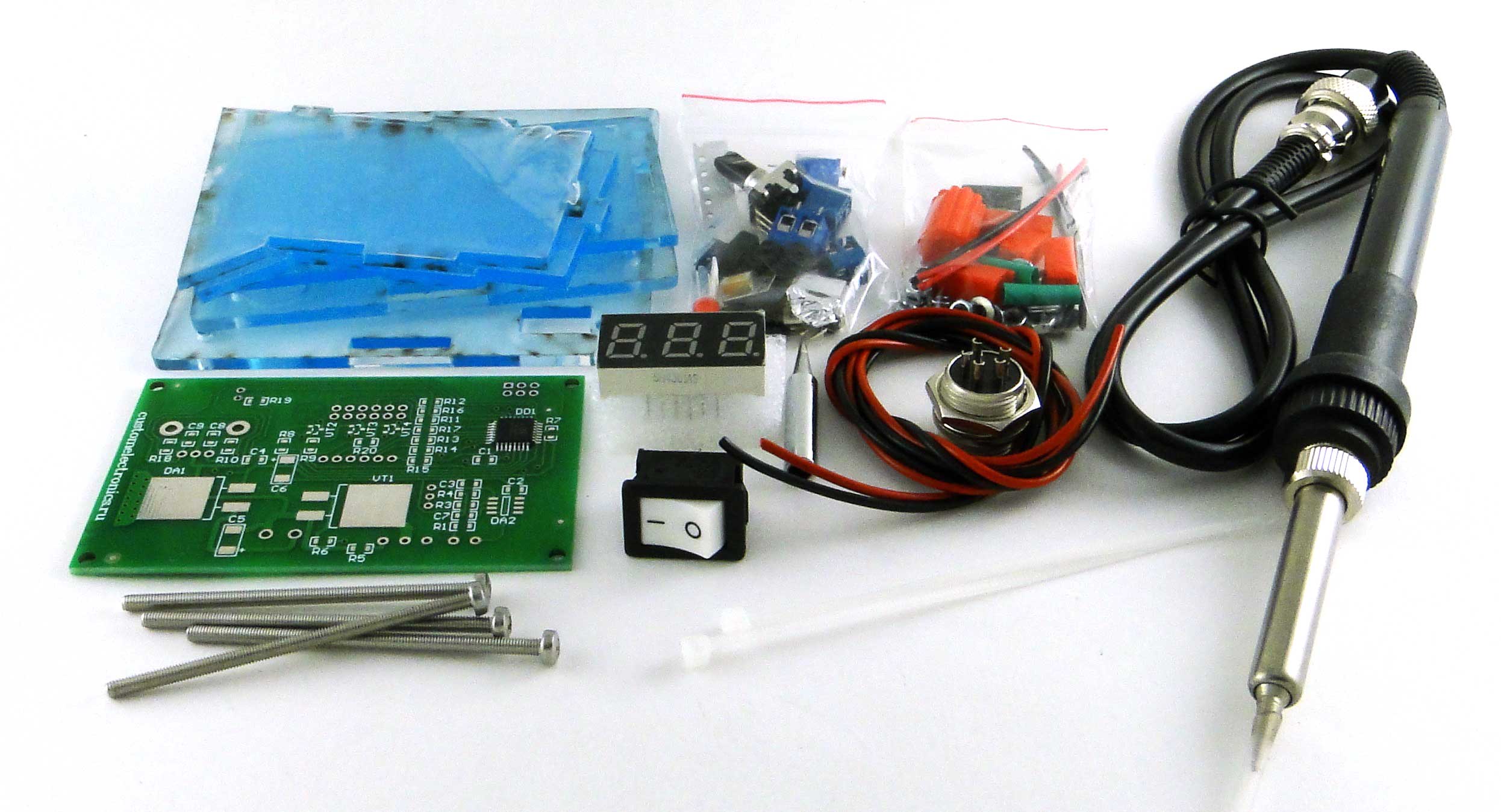
Component List
The following components and materials will be required to assemble the circuit board and case:
- BQ1. Encoder EC12E24204A8
- C5. Tantalum capacitor 35V, 10µF, size C
- C1-C4, C7-C9. Ceramic capacitors 0.1 microfarad in case 0805
- C6. Tantalum capacitor 16V, 22µF, size C
- DD1. ATmega8A-AU microcontroller in TQFP32 package
- DA1. Stabilizer L7805ACD2T-TR to 5V in the D2PAK package
- DA2. Operational amplifier LM358ADT in SO8 package
- HG1. Seven-segment three-digit indicator with a common cathode BC56-12GWA. Also, the board provides a seat for a cheap analogue .
- HL1. Any indicator LED for a current of 20mA with a pitch of 2.54 mm
- R1, R6. Resistors 300 Ohm, 0805 body - 2pcs
- R4, R7-R20. Resistors 1kOhm, building 0805 - 15pcs
- R3. Resistor 100kΩ, body 0805
- R5. 1MΩ resistor, 0805 body
- R2. Trimmer 3296W 100kΩ
- VT1. Field effect transistor IRF3205SPBF in D2PAK package
- VT2-VT4. BC547BTA Transistors in the SOT323 package - 3pcs
- XS2. Two-prong terminal with lead pitch 5.08 mm
- Xs1. Terminal for two pins with lead pitch 3.81mm
- XS3. Three-prong terminal with lead pitch 3.81mm
- XS4. PLS-06 programming connector
- Connector for soldering iron
- Power Switch SWR-45 BW (13-KN1-1)
- Soldering iron . We will write about it later
- Details from plexiglas for the body (links to files for cutting plexiglass at the end of the article)
- Encoder knob. You can buy it, or you can print it on a 3D printer. File for downloading the model at the end of the article
- Racks. They can also be printed, but you can use ordinary sleeves with a hole of 3mm and a height of 10mm.
- Screw M3x60 - 4pcs
- Nut M3 - 8pcs
- M3 washer - 4pcs
- M3 washer increased - 8 pieces
- M3 horizontal washer - 8pcs
- Also required for the assembly of assembly wires, ties and shrink tube
Here is a set of all the details:
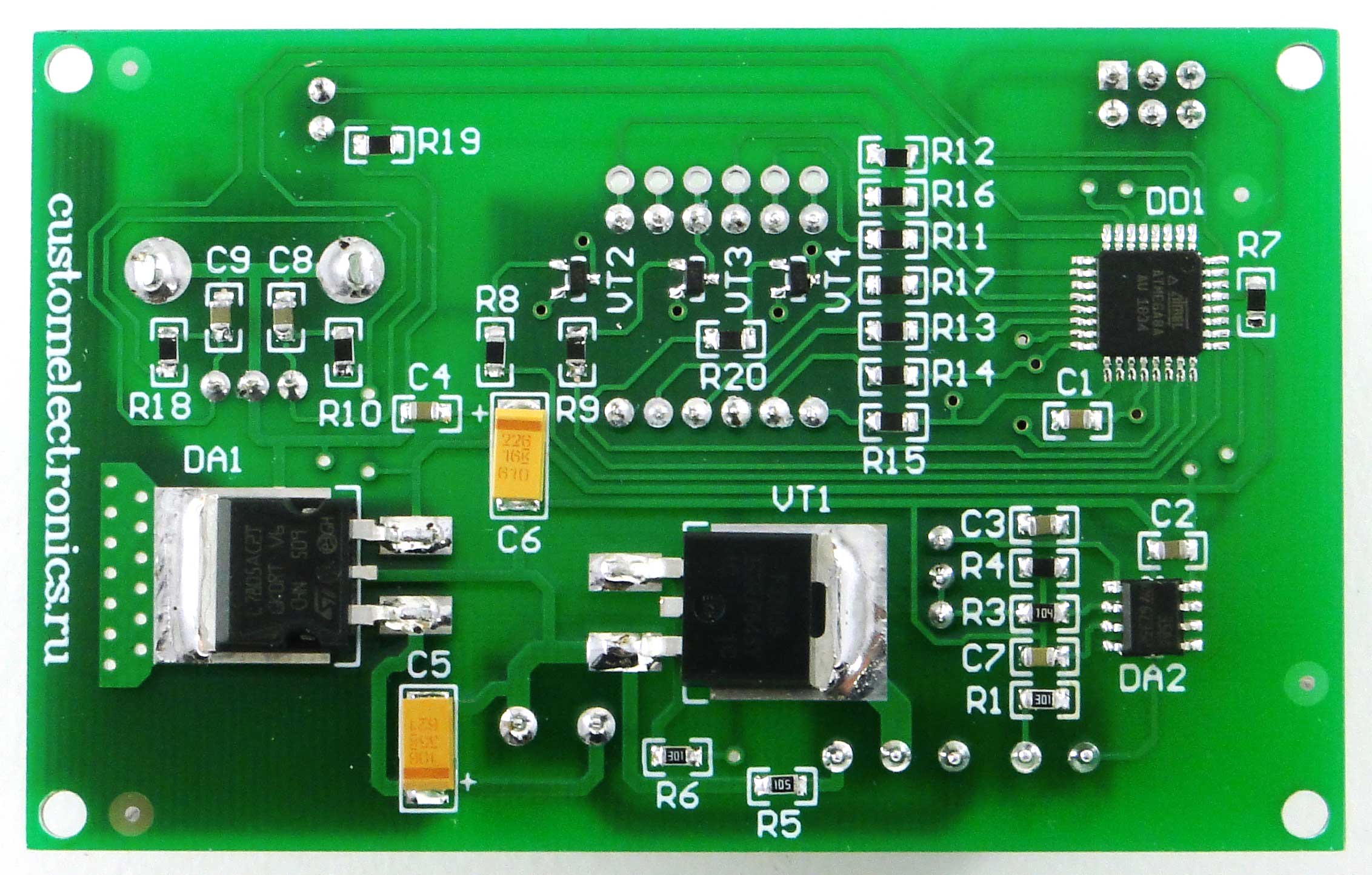
PCB Mounting
When assembling it is convenient to use assembly drawings:
You need to start with the installation of SMD components. Install elements on the board according to the list of elements. When installing elements, it is important to follow the orientation of the tantalum capacitors and the operational amplifier. The first output of DA2 is determined by the bevel on the body.
If everything is assembled correctly, the board should look like this.
Please note that we used 1kOhm resistors without marking.
Next, you need to install the output elements on the board in accordance with the list of elements. Long LED output is a plus. The seven-segment indicator is set “points” down.
Here is the front side of the PCB assembly:
Assembly of the case and volume installation
Power and soldering iron are connected according to the following scheme:
Before assembling the case, it is necessary to prepare a switch and a connector. The switch must be connected to the break of the red wire so that on one contact of the switch there is a short piece of red thick wire, and on the second a long one.
You need to connect short red wires to the first and fifth pins of the soldering iron connector, and the rest to black.
Heat-shrink tubing should be worn on the switch and the connector and tinned all the free ends of the wires, so that later it was more convenient to fasten them to the terminals.
Next, you need to install a switch and a soldering iron connector on the front panel. Please note that the switch may be installed tightly and it may be necessary to modify the slot for it with a file.
Then you should connect the first pin of the connector to the first pin of the board, the second to the second, and so on. in accordance with the above figure. The power supply on the board must be connected to the red short wire from the switch, and to the minus the black wire.
Microcontroller firmware and first start
In the upper left corner of the board there is a standard ISP connector for flashing AVR microcontrollers.
You can flash the microcontroller with any programmer you have, for example USBasp. If the programmer provides power itself supplies 5V, then connect the external is not required. You can also find the firmware file at the end of the article.
Configuration bits! You must enable CKSEL0, CKSEL2, CKSEL3, SUT0, BOOTSZ0, BOOTSZ1 and SPIEN! That is, a change of default settings is required to start the controller at a clock frequency of 2 MHz.
Now you can connect a soldering iron and supply the input supply voltage (from 12 to 24V). After switching on, the soldering iron should start to heat up, and the temperature reading on the indicator should increase. When the encoder shaft rotates, the value of the required temperature should change.
Completion of assembly
Side walls are installed without any mounts. Now it remains only to insert the rear cover into the grooves, tighten the nuts, pull the power wires through the hole and fix them with cable clamps. Remember that the plexiglass parts are quite fragile and do not overtighten the fasteners!
Calibration
For precise temperature adjustment using a trimmer resistor. The front panel has a special opening for access to it.
When calibrating, first of all it is necessary to bring the sting to the temperature at which the solder melts. You can just set the encoder very high temperature immediately. Then, having collected a solder ball on a sting, it is required to warm up the thermocouple. There are special measuring devices for such purposes, but an ordinary multimeter with a thermocouple will do. Next, by rotating the trimming shaft, ensure that the measured value of the soldering station matches the readings of the external thermocouple.
During calibration, remember that the more time you give a soldering iron to stabilize the temperature, the more accurately you will be able to adjust it. Also note that the trimmer is multi-loop and one revolution changes the temperature very slightly. That is, you need to turn it boldly and a lot.
Video
We also prepared a video instruction:
Links
Direct links to all the necessary files for downloading can be found on the main page of the project .
This device also has a version on a one-sided board using only pin components. Find it here
Once again I want to emphasize that we provide all the necessary and very detailed information for the independent production of this device, and additionally we provide the opportunity to purchase it in the form of a set ( one , two , three ).
PS: and we are also preparing a hairdryer) thanks for your interest in our activities!
Source: https://habr.com/ru/post/417471/
All Articles