Superconducting transformer almost with their own hands
In the near 2016, one young, but very impressionable fourth-year student of the Faculty of Energy was influenced by an article in which the author very popularly showed what today's high-temperature superconductors (hereinafter HTSC) are today. Blinded by the desire to revive a rather monotonous and extremely conservative power industry in his soul, making his way through a veil of contradictions and an acute shortage of finances, the young bachelor with his colleagues still built a transformer with windings of a high-temperature superconductor.
Enjoy reading!
Why make transformers superconducting?
The current transformer products have truly achieved in some sense an ideal. Large power transformers, the ones that stand in brick or iron transformer substations (TP-ears) in your yard, as well as larger representatives have an efficiency of about 99%. A huge number of regulatory documents regulates the work, diagnostics, method of installation and creation of such transformers, and at conferences and exhibitions there are more and more new representatives with an innovative nut in the core of the magnetic core or revolutionary oil with a low concentration of gases dissolved in it.
')

Typical representative of power transformers
And, it would seem, where we are fools to climb into this highly polished area of engineering thought. Are the extra half-percent efficiencies that the superconducting windings of a transformer can produce, worth the cost and organization of a special cryogenic farm, retraining engineers and re-equipment of production? Why reinvent the wheel? Primary analysis shows that there is no need. However, let me give one argument, which was the reason why this article later became possible: “What if the bike is an emergency?”.
The advantages of a transformer with HTS windings over conventional ones:
- The almost complete absence of energy losses in the windings (the wires are superconducting, they do not heat up);
- Explosion and fire safety (liquid nitrogen, unlike transformer oil, does not emit explosive gases);
- Smaller mass and dimensions (current density in a superconducting wire may be 10 times higher than in copper, at equal voltage);
- Ability to limit short-circuit currents .
Despite the strong component of the first three advantages, they all fade before the oppression of the huge price that has to be paid for superconductivity. Therefore, I am afraid that the commercial success of HTS transformers can occur, except in particularly demanding types of military and space technology or at special fire-safety facilities. However, the fourth property can dramatically change the picture and to me personally it alone alone seems sufficient to not only draw attention to the HTS paradigm, but also to do some research. Actually, as many of my colleagues around the world did, take at least work [1-3].
What is the trick here?
About current limiting physics
At the moment, speaking of HTS wires in the context of the power industry, we almost always speak of composite HTS tapes based on ceramic compounds. As can be seen from the image below, the superconductor (YBCO layer) deposited on a metal substrate is covered on all sides with a certain protective layer. This protective layer can be some metals and their alloys, such as copper. Naturally, these materials do not have superconducting properties at liquid nitrogen temperature, and therefore if superconductivity for some reason disappears from YBCO ceramics, then all the current is parallelized between these layers, in accordance with their resistive resistance.
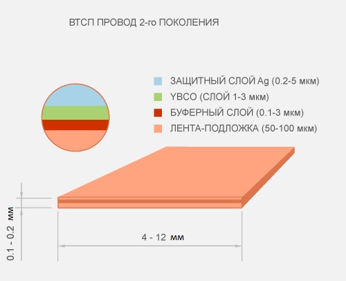
Any current is proportional to the voltage applied to a given resistance, which means that if, out of the blue, resistance appeared where it did not exist before (superconductivity collapsed), then the current (at a constant voltage) will decrease. Moreover, the degree of this reduction depends on the resistance of the materials surrounding, the HTS layer. But how to destroy superconductivity? There are actually 2 fundamental ways: to raise the temperature above the critical one, at which superconductivity cannot exist or act on HTSC with a magnetic field above the critical one. Moreover, if a current flows through a superconductor, it also creates a magnetic field that tries to penetrate this superconductor, and if the current creates too large a field, then the superconductivity begins to gradually break down. The current at which superconductivity began to break down is commonly called critical .
Build a transformer!
All right! Now, I am sure you understand enough to start building a transformer, and believe me, this was a really exciting journey for me, because if winding the wire for an ordinary transformer (hello to those who shook it) is a very meticulous and rather tedious thing, then the complexity of the HTS transformer increases by several times. Especially when such a device is assembled from scrap materials. Understand why!
Winding cages
One of the serious shortcomings of HTS transformers is that the core is not and cannot be superconducting. Therefore, we have two options for how to act, heat and hydro-insulate the core from the windings, increasing the distance between it and the windings and reducing the efficiency, or shove the core into nitrogen along with the windings, creating a large boiler for nitrogen, since the losses at idling of the transformer are nowhere put it up We decided to go the first way, making a cryostat in the form of a hollow cylinder. For which purpose, as the framework for the secondary winding (which is closer to the core), we chose this:
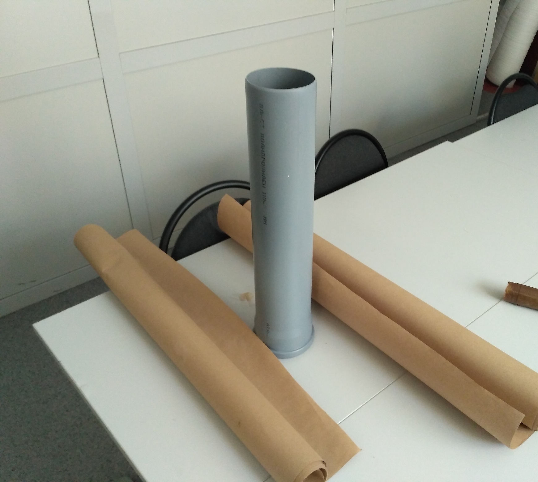
Polypropylene pipe and wrapping paper near it
Pipe with an internal diameter of 100 mm. made of polypropylene is an ideal hydro insulator, but not a very good heat insulator. Moreover, some types of plastic tend to shrink at low temperatures, because of which the winding wound directly on such a pipe can be deformed together with the pipe. Therefore, it was decided to reinforce this pipe additionally by wrapping it over paper soaked in epoxy. There were no problems with paper, you can get one in abundance at the exit from various (large) building stores (ala Leroy), there it is free. With a compound heavier. We had no experience with homemade textolites based on paper, and we did not know how the paper-impregnated frame would behave at -196 degrees Celsius. We consulted and decided to take the first epoxy resin brand ED-20. When buying a resin, we were warned that the hardener (the second component with which the resin is mixed, after which it hardens during the chemical reaction) works within 20 minutes. Why it immediately became clear that it would be impossible to hesitate and it would be necessary to soak the paper quickly. To do this, faithful colleagues appeared in the form of a human conveyor.
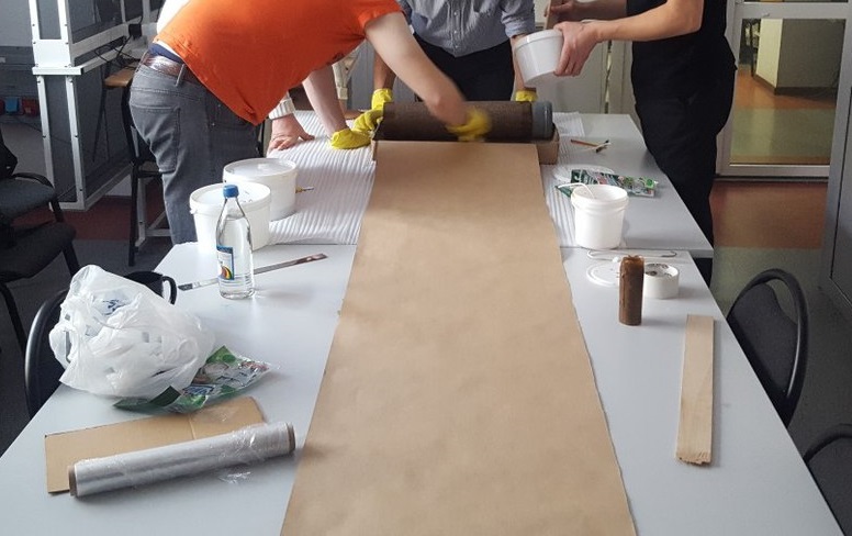
Improvised epoxy paper impregnation conveyor
The smell was, frankly, not very. And take care of your hands when working with compounds!
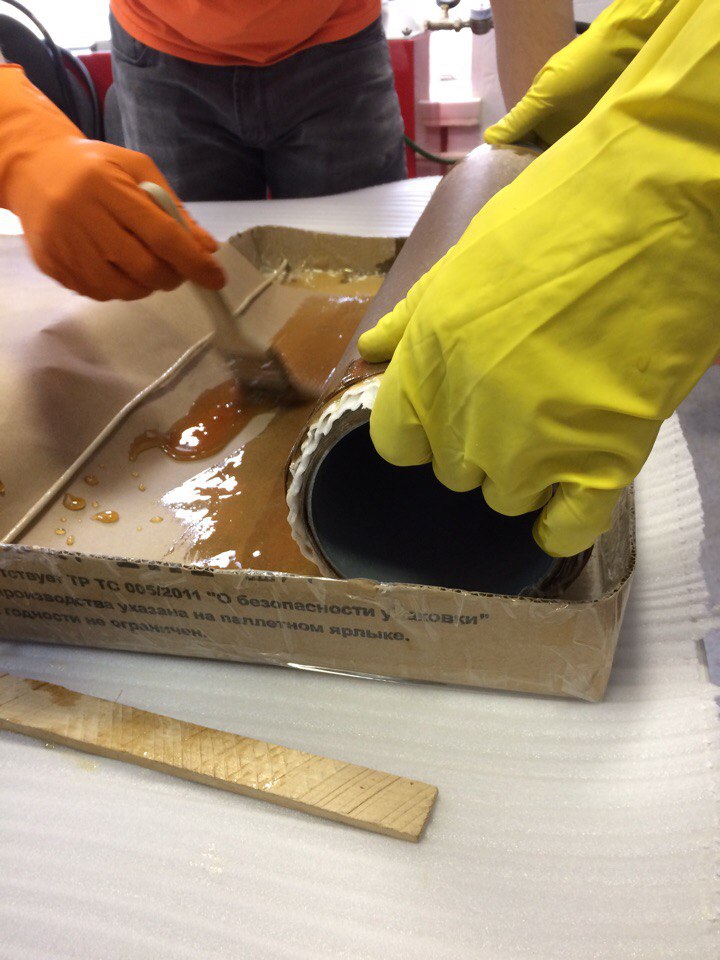
Paper impregnation process
The second frame (for the outer winding) was made in the image of the first and directly on top of it. To prevent the carcasses from sticking together, they put a little bit of random material that could later be pulled off. The result was:
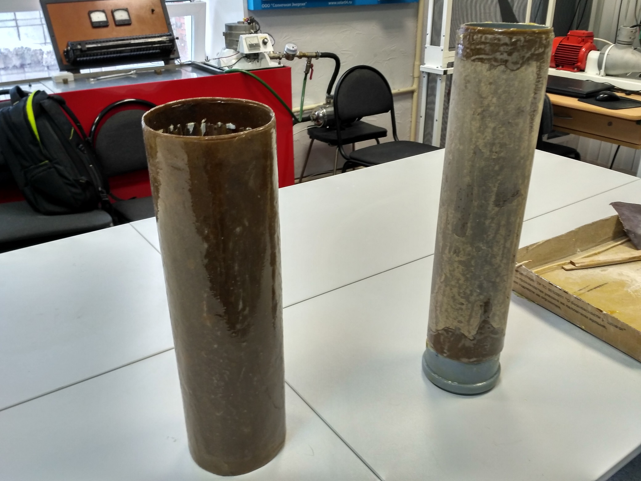
Prefabricated winding cages
Summarizing this part, I will say that there is probably no cheaper way to create two non-magnetic, non-metallic, cryostable and sufficiently durable framework. The most expensive element in the creation of the frame was of course the compound ~ 500 r. / Kg., Followed by the PP pipe, and then brushes, gloves - this is optional.
Windings
Perhaps the central and most expensive element of this story are the HTSC windings themselves. The reason why the word “almost” appears in the title of the article is the price. 40 meters of HTS tapes 4 mm wide and 0.1 mm thick, with a critical current of 80 A. We purchased it at a price of 2500 rubles per meter. It is clear nat. a person is unlikely to pay for this. Let us look at their dazzlingly precious greatness.
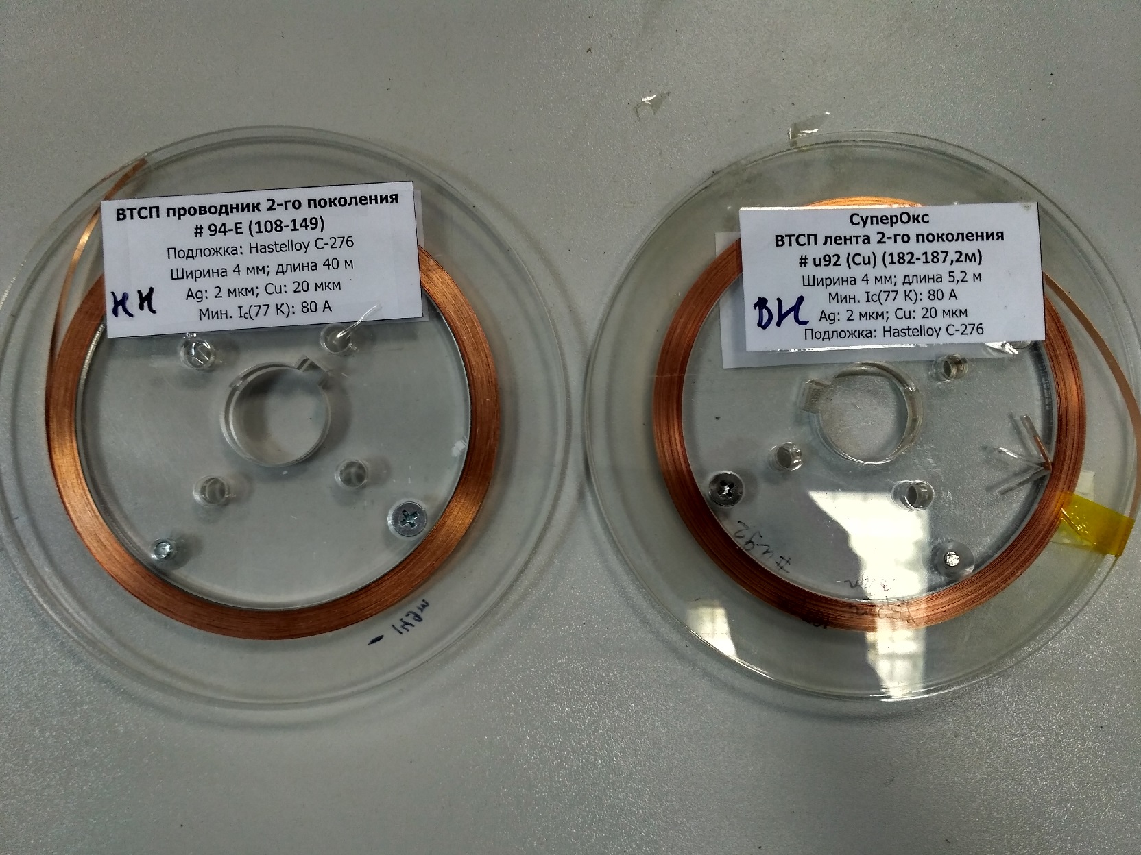
Dazzlingly expensive part of the project described
In addition to the high cost of HTS tape is also very capricious material. It does not like strong overheating (over 500 degrees), it has a large limiting bending radius (about 20 mm, if it starts, deformation of the superconductor will begin), it also cannot be twisted, crushed, beaten. All this turns the work with HTS wires into something like jewelry. How are we going to wind?
To be honest, the method of winding the tape on the frame is probably the most primitive one. The tape is covered along one side with a Kapton tape , and the edges of the tape extending beyond the limits of the tape are glued together with the tape to the frame. As a result, in the process of winding, we get two factors that hold the winding on the frame: adhesive tape adhesion and the textolite surface and the friction force of the tape on the same surface. In the end, surprisingly, it turned out pretty reliable.
Kapton tape is not allocated randomly. The fact is that not every material can be reliable insulation at low temperatures. For example, the usual tape becomes almost glass and sits down. Electrical tape also sits down. Insulating varnishes crack (though not all), PVC insulation also shrinks. Kapton (or polyimide) adhesive tape behaves extremely calmly at low temperatures (as well as at high temperatures), it is traditionally chosen for HTS wires when you need to do something “quickly”, although it must be said that it is not cheap compared to the usual scotch tape When you need to do something solid, use all the coating also on the basis of polyimide.
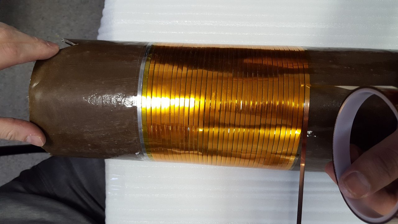
The process of winding the outer (primary) winding
Motali, in fact, a transformer with the number of turns 50:25, in practice turned out a little less, but not the essence. The primary winding (external) was one-way (one spiral across the entire height), the secondary winding (internal) was two-way (two spirals go, alternating). What actually gives the critical current primary = 80 A and for the secondary 160A. If we take into account that the mains voltage (under which the transformer was made) = 220 V. This results in about 10 kW of transmitted power with virtually no losses, in a fairly small volume. The results of the winding:
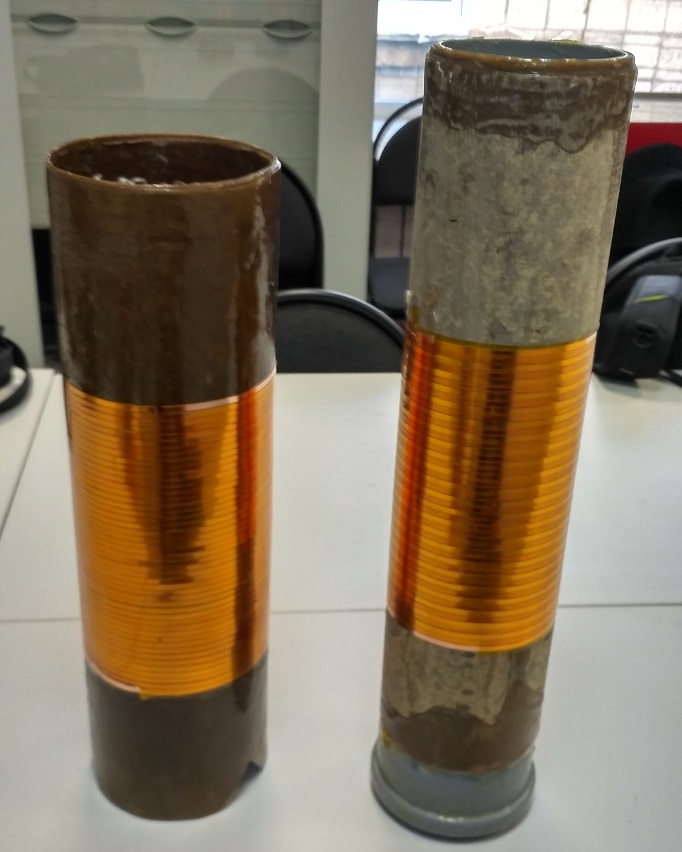
Primary (left) and secondary (right) windings of HTS transformer
Soldering
We got to the very nervous process in the manufacture of a transformer. As mentioned above, a superconductor does not like high temperatures. When we speak of a copper wire capable of carrying 60-80 Amps for a long time without overheating, we mean sections of 16 or 25 mm ^ 2. These are rather massive and unruly wires that are hard to give the desired elegant shape for comfortable soldering with 4 mm HTS tape. If you take a fairly powerful soldering iron and a simple solder, then you can overheat the tape. Therefore, it is better to take Indium-Tin solder with a melting point of ~ 103 degrees. C. It is even better to melt it in a solder bath, cover the tape and wire with soldering acid and get a fabulous reflection of self-adoration from a job well done in the reflection of hot metal.
Nuance. It is better to solder current contacts, not sparing the area of the tape, for a better current lead. We took 3 cm. Tape on the surface of contact with the current contact, but can be more. We removed the voltage contacts a few centimeters from the current in order not to measure the voltage drop at the point of contact, but directly at the winding. Unfortunately, only the photo of the final of this action has been preserved.
Winding with contacts
Cryostat
The final and most artisanal part of our production. The cryostat was made of foam and acrylic sealant. And that's all. Unfortunately, not every grade of foam will work. Foam with large granules in contact with the nitrogen on it immediately self-destruct with a bang and a crash.
Incorrect foam (left) and correct foam (right)
As for the sealant, then, aside from the jokes, they took the cheapest of those that were. I do not know what the trick is. The main thing is that the sealant should be acrylic, not silicone, because the latter (as we were assured in the store) can eat foam.
The cryostat was prefabricated, squares with round holes were cut out, so that the whole structure would fit inside, with a pipe sticking out outside the cryostat into which the magnetic core was supposed to be placed in the future. In other words:
Precast cryostat
As can be seen in the photo, the joints of this whole structure were greased and greased and impregnated with sealant. On hand, the fact that the sealant freezes in the presence of nitrogen, to the touch resembles a very thick cheese, and performs its functions extremely well. At the last stage, a special bottom is cut under the pipe-frame, on which it is installed and, finally, the whole structure is assembled into a single HTS transformer.

HTS transformer
As a result, we received:
VTsPT-10000, 220/110 V, 50/100 A, OHL
Experiments
I think every experimenter at least once experienced this mixture of thrill and ruthlessness with which he subjected the torments of his "newly made beast." Of course the HTS transformer was created to be incinerated. However, we will incinerate him carefully - scientifically.
Here I will show the main experience for the sake of which the transformer was made. Let us short-circuit the secondary winding and with the help of a switch, apply voltage from the mains (220 V) to the primary winding. Since the resistances of the primary winding and the secondary winding magnetically connected with it (through the air) are small, sufficiently large currents will flow in the circuits. These currents will exceed the critical level of 80 A and, therefore, destroy the superconductivity, because of which the HTSC winding will gradually acquire the final electrical resistance, which in turn will cause a current limitation. What we fix in the form of a distorted sinusoid current. And the appearance on the oscillogram of the voltage of some finite values (instead of zero in the normal mode). Measurements will be carried out using the device unexpected for a given experience: a power quality analyzer . It is unexpected because the sampling frequency of this device in the oscilloscope mode leaves much to be desired. But what to do. Nevertheless, let's take a look at the qualitative picture of what is happening.
Oscillograms of currents (dots in the graphs correspond to the actual captured data)
The oscillograms on the left (for comparison) show a short circuit mode if you do not fill the transformer with liquid nitrogen: we see a slightly distorted but quiet sinusoid of short circuit current, which after a period (half of the period shown in the figure) is turned off by an automatic switch. On the right is the short-circuit mode if the cryostat is pre-filled with liquid nitrogen: we see a strong initial increase in current, which gradually (starting from 150 A) is bent under the action of the increasing resistance. However, due to the larger value of the short-circuit current, the circuit breaker operates already in the first half period.
Alas, for the time being we are content only with these qualitative results, but soon we will definitely make many others.
Conclusion
Of course, the HTS transformer leaves behind a lot of contradictions. These contradictions are manifested even in the artisanal method of manufacturing such an uneasy device. What to say about the real acting samples, which you can find on [1,3]. Real HTS electric power industry has galloped far ahead with the development of cables and current limiters, experiencing difficulties even in these more advanced divisions of it. It is quite popular to get acquainted with them without leaving this site, for example here .
Nevertheless, no matter how contradictory this field of engineering knowledge might be, in the end, the one who can justify his case is right, so we will try.
And in any case, it is terribly interesting!
Thank you for attention!
Yours sincerely, DOK.
Thanks also to:
Vysotsky Vitaly Sergeevich and the VNIIKP team for helping and advising in this difficult path.
Pavlyuchenko Dmitry Anatolyevich for his tremendous support and desire to develop this area from scratch!
Enjoy reading!
Why make transformers superconducting?
The current transformer products have truly achieved in some sense an ideal. Large power transformers, the ones that stand in brick or iron transformer substations (TP-ears) in your yard, as well as larger representatives have an efficiency of about 99%. A huge number of regulatory documents regulates the work, diagnostics, method of installation and creation of such transformers, and at conferences and exhibitions there are more and more new representatives with an innovative nut in the core of the magnetic core or revolutionary oil with a low concentration of gases dissolved in it.
')
Typical representative of power transformers
And, it would seem, where we are fools to climb into this highly polished area of engineering thought. Are the extra half-percent efficiencies that the superconducting windings of a transformer can produce, worth the cost and organization of a special cryogenic farm, retraining engineers and re-equipment of production? Why reinvent the wheel? Primary analysis shows that there is no need. However, let me give one argument, which was the reason why this article later became possible: “What if the bike is an emergency?”.
The advantages of a transformer with HTS windings over conventional ones:
- The almost complete absence of energy losses in the windings (the wires are superconducting, they do not heat up);
- Explosion and fire safety (liquid nitrogen, unlike transformer oil, does not emit explosive gases);
- Smaller mass and dimensions (current density in a superconducting wire may be 10 times higher than in copper, at equal voltage);
- Ability to limit short-circuit currents .
Despite the strong component of the first three advantages, they all fade before the oppression of the huge price that has to be paid for superconductivity. Therefore, I am afraid that the commercial success of HTS transformers can occur, except in particularly demanding types of military and space technology or at special fire-safety facilities. However, the fourth property can dramatically change the picture and to me personally it alone alone seems sufficient to not only draw attention to the HTS paradigm, but also to do some research. Actually, as many of my colleagues around the world did, take at least work [1-3].
What is the trick here?
About current limiting physics
At the moment, speaking of HTS wires in the context of the power industry, we almost always speak of composite HTS tapes based on ceramic compounds. As can be seen from the image below, the superconductor (YBCO layer) deposited on a metal substrate is covered on all sides with a certain protective layer. This protective layer can be some metals and their alloys, such as copper. Naturally, these materials do not have superconducting properties at liquid nitrogen temperature, and therefore if superconductivity for some reason disappears from YBCO ceramics, then all the current is parallelized between these layers, in accordance with their resistive resistance.
Any current is proportional to the voltage applied to a given resistance, which means that if, out of the blue, resistance appeared where it did not exist before (superconductivity collapsed), then the current (at a constant voltage) will decrease. Moreover, the degree of this reduction depends on the resistance of the materials surrounding, the HTS layer. But how to destroy superconductivity? There are actually 2 fundamental ways: to raise the temperature above the critical one, at which superconductivity cannot exist or act on HTSC with a magnetic field above the critical one. Moreover, if a current flows through a superconductor, it also creates a magnetic field that tries to penetrate this superconductor, and if the current creates too large a field, then the superconductivity begins to gradually break down. The current at which superconductivity began to break down is commonly called critical .
Build a transformer!
All right! Now, I am sure you understand enough to start building a transformer, and believe me, this was a really exciting journey for me, because if winding the wire for an ordinary transformer (hello to those who shook it) is a very meticulous and rather tedious thing, then the complexity of the HTS transformer increases by several times. Especially when such a device is assembled from scrap materials. Understand why!
Winding cages
One of the serious shortcomings of HTS transformers is that the core is not and cannot be superconducting. Therefore, we have two options for how to act, heat and hydro-insulate the core from the windings, increasing the distance between it and the windings and reducing the efficiency, or shove the core into nitrogen along with the windings, creating a large boiler for nitrogen, since the losses at idling of the transformer are nowhere put it up We decided to go the first way, making a cryostat in the form of a hollow cylinder. For which purpose, as the framework for the secondary winding (which is closer to the core), we chose this:
Polypropylene pipe and wrapping paper near it
Pipe with an internal diameter of 100 mm. made of polypropylene is an ideal hydro insulator, but not a very good heat insulator. Moreover, some types of plastic tend to shrink at low temperatures, because of which the winding wound directly on such a pipe can be deformed together with the pipe. Therefore, it was decided to reinforce this pipe additionally by wrapping it over paper soaked in epoxy. There were no problems with paper, you can get one in abundance at the exit from various (large) building stores (ala Leroy), there it is free. With a compound heavier. We had no experience with homemade textolites based on paper, and we did not know how the paper-impregnated frame would behave at -196 degrees Celsius. We consulted and decided to take the first epoxy resin brand ED-20. When buying a resin, we were warned that the hardener (the second component with which the resin is mixed, after which it hardens during the chemical reaction) works within 20 minutes. Why it immediately became clear that it would be impossible to hesitate and it would be necessary to soak the paper quickly. To do this, faithful colleagues appeared in the form of a human conveyor.
Improvised epoxy paper impregnation conveyor
The smell was, frankly, not very. And take care of your hands when working with compounds!
Paper impregnation process
The second frame (for the outer winding) was made in the image of the first and directly on top of it. To prevent the carcasses from sticking together, they put a little bit of random material that could later be pulled off. The result was:
Prefabricated winding cages
Summarizing this part, I will say that there is probably no cheaper way to create two non-magnetic, non-metallic, cryostable and sufficiently durable framework. The most expensive element in the creation of the frame was of course the compound ~ 500 r. / Kg., Followed by the PP pipe, and then brushes, gloves - this is optional.
Windings
Perhaps the central and most expensive element of this story are the HTSC windings themselves. The reason why the word “almost” appears in the title of the article is the price. 40 meters of HTS tapes 4 mm wide and 0.1 mm thick, with a critical current of 80 A. We purchased it at a price of 2500 rubles per meter. It is clear nat. a person is unlikely to pay for this. Let us look at their dazzlingly precious greatness.
Dazzlingly expensive part of the project described
In addition to the high cost of HTS tape is also very capricious material. It does not like strong overheating (over 500 degrees), it has a large limiting bending radius (about 20 mm, if it starts, deformation of the superconductor will begin), it also cannot be twisted, crushed, beaten. All this turns the work with HTS wires into something like jewelry. How are we going to wind?
To be honest, the method of winding the tape on the frame is probably the most primitive one. The tape is covered along one side with a Kapton tape , and the edges of the tape extending beyond the limits of the tape are glued together with the tape to the frame. As a result, in the process of winding, we get two factors that hold the winding on the frame: adhesive tape adhesion and the textolite surface and the friction force of the tape on the same surface. In the end, surprisingly, it turned out pretty reliable.
Kapton tape is not allocated randomly. The fact is that not every material can be reliable insulation at low temperatures. For example, the usual tape becomes almost glass and sits down. Electrical tape also sits down. Insulating varnishes crack (though not all), PVC insulation also shrinks. Kapton (or polyimide) adhesive tape behaves extremely calmly at low temperatures (as well as at high temperatures), it is traditionally chosen for HTS wires when you need to do something “quickly”, although it must be said that it is not cheap compared to the usual scotch tape When you need to do something solid, use all the coating also on the basis of polyimide.
The process of winding the outer (primary) winding
Motali, in fact, a transformer with the number of turns 50:25, in practice turned out a little less, but not the essence. The primary winding (external) was one-way (one spiral across the entire height), the secondary winding (internal) was two-way (two spirals go, alternating). What actually gives the critical current primary = 80 A and for the secondary 160A. If we take into account that the mains voltage (under which the transformer was made) = 220 V. This results in about 10 kW of transmitted power with virtually no losses, in a fairly small volume. The results of the winding:
Primary (left) and secondary (right) windings of HTS transformer
Soldering
We got to the very nervous process in the manufacture of a transformer. As mentioned above, a superconductor does not like high temperatures. When we speak of a copper wire capable of carrying 60-80 Amps for a long time without overheating, we mean sections of 16 or 25 mm ^ 2. These are rather massive and unruly wires that are hard to give the desired elegant shape for comfortable soldering with 4 mm HTS tape. If you take a fairly powerful soldering iron and a simple solder, then you can overheat the tape. Therefore, it is better to take Indium-Tin solder with a melting point of ~ 103 degrees. C. It is even better to melt it in a solder bath, cover the tape and wire with soldering acid and get a fabulous reflection of self-adoration from a job well done in the reflection of hot metal.
Nuance. It is better to solder current contacts, not sparing the area of the tape, for a better current lead. We took 3 cm. Tape on the surface of contact with the current contact, but can be more. We removed the voltage contacts a few centimeters from the current in order not to measure the voltage drop at the point of contact, but directly at the winding. Unfortunately, only the photo of the final of this action has been preserved.
Winding with contacts
Cryostat
The final and most artisanal part of our production. The cryostat was made of foam and acrylic sealant. And that's all. Unfortunately, not every grade of foam will work. Foam with large granules in contact with the nitrogen on it immediately self-destruct with a bang and a crash.
Incorrect foam (left) and correct foam (right)
As for the sealant, then, aside from the jokes, they took the cheapest of those that were. I do not know what the trick is. The main thing is that the sealant should be acrylic, not silicone, because the latter (as we were assured in the store) can eat foam.
The cryostat was prefabricated, squares with round holes were cut out, so that the whole structure would fit inside, with a pipe sticking out outside the cryostat into which the magnetic core was supposed to be placed in the future. In other words:
Precast cryostat
As can be seen in the photo, the joints of this whole structure were greased and greased and impregnated with sealant. On hand, the fact that the sealant freezes in the presence of nitrogen, to the touch resembles a very thick cheese, and performs its functions extremely well. At the last stage, a special bottom is cut under the pipe-frame, on which it is installed and, finally, the whole structure is assembled into a single HTS transformer.
HTS transformer
As a result, we received:
VTsPT-10000, 220/110 V, 50/100 A, OHL
Explanation
HTS T - Last Letter Means Transformer
10,000 - power in VA
220/100 - the rated voltage of the primary / secondary windings
50/100 - rated primary / secondary currents
OHL - work under very cold conditions
10,000 - power in VA
220/100 - the rated voltage of the primary / secondary windings
50/100 - rated primary / secondary currents
OHL - work under very cold conditions
Experiments
I think every experimenter at least once experienced this mixture of thrill and ruthlessness with which he subjected the torments of his "newly made beast." Of course the HTS transformer was created to be incinerated. However, we will incinerate him carefully - scientifically.
Here I will show the main experience for the sake of which the transformer was made. Let us short-circuit the secondary winding and with the help of a switch, apply voltage from the mains (220 V) to the primary winding. Since the resistances of the primary winding and the secondary winding magnetically connected with it (through the air) are small, sufficiently large currents will flow in the circuits. These currents will exceed the critical level of 80 A and, therefore, destroy the superconductivity, because of which the HTSC winding will gradually acquire the final electrical resistance, which in turn will cause a current limitation. What we fix in the form of a distorted sinusoid current. And the appearance on the oscillogram of the voltage of some finite values (instead of zero in the normal mode). Measurements will be carried out using the device unexpected for a given experience: a power quality analyzer . It is unexpected because the sampling frequency of this device in the oscilloscope mode leaves much to be desired. But what to do. Nevertheless, let's take a look at the qualitative picture of what is happening.
Oscillograms of currents (dots in the graphs correspond to the actual captured data)
The oscillograms on the left (for comparison) show a short circuit mode if you do not fill the transformer with liquid nitrogen: we see a slightly distorted but quiet sinusoid of short circuit current, which after a period (half of the period shown in the figure) is turned off by an automatic switch. On the right is the short-circuit mode if the cryostat is pre-filled with liquid nitrogen: we see a strong initial increase in current, which gradually (starting from 150 A) is bent under the action of the increasing resistance. However, due to the larger value of the short-circuit current, the circuit breaker operates already in the first half period.
Alas, for the time being we are content only with these qualitative results, but soon we will definitely make many others.
Conclusion
Of course, the HTS transformer leaves behind a lot of contradictions. These contradictions are manifested even in the artisanal method of manufacturing such an uneasy device. What to say about the real acting samples, which you can find on [1,3]. Real HTS electric power industry has galloped far ahead with the development of cables and current limiters, experiencing difficulties even in these more advanced divisions of it. It is quite popular to get acquainted with them without leaving this site, for example here .
Nevertheless, no matter how contradictory this field of engineering knowledge might be, in the end, the one who can justify his case is right, so we will try.
And in any case, it is terribly interesting!
Thank you for attention!
Yours sincerely, DOK.
Thanks also to:
Vysotsky Vitaly Sergeevich and the VNIIKP team for helping and advising in this difficult path.
Pavlyuchenko Dmitry Anatolyevich for his tremendous support and desire to develop this area from scratch!
Literature
1. Dai S. et al. Development of a 1250-kVA superconducting transformer and its demonstration at the superconducting substation // IEEE Transactions on Applied Superconductivity. - 2016. - V. 26. - №. 1. - p. 1-7.
2. Manusov V.Z., Aleksandrov N.V. Restriction of short-circuit currents using transformers with high-temperature superconducting windings // Bulletin of Tomsk Polytechnic University. - 2013. - T. 323. - №. four.
3. Lapthorn AC et al. HTS transformer: Construction details, test results, and noted failure mechanisms // IEEE Transactions on Power Delivery. - 2011. - V. 26. - №. 1. - p. 394-399.
Source: https://habr.com/ru/post/410939/
All Articles