Solar panel on the balcony: charge controller testing
Hello geektimes!
In the previous part , the operation of the BMS board was examined and verified, ensuring the correct charge of the lithium-ion battery. The Chinese mail finally delivered the Solar charge controller, so it's time to test it.
')
Test results under the cut.
This device is basic throughout the system - it is the controller that provides the interaction of all components - the solar panel, the load and the battery (it is needed only if we want to store energy in the battery, if we give energy directly to the electricity grid, we need a different type of grid tie controller).
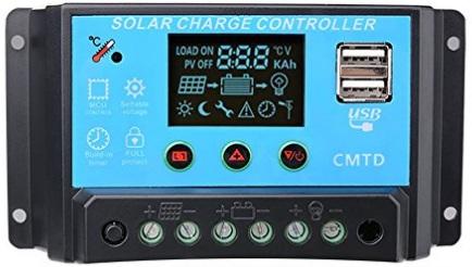
There are quite a lot of controllers for small currents (10-20A) on the market, but since In our case, a lithium battery is used instead of a lead one, then we need to choose a controller with adjustable parameters. A controller was purchased, as in the photo, the issue price from $ 13 on eBay to $ 20-30, depending on the greed of local sellers. The controller is proudly called the “Intelligent PWM Solar Panel Charge Controller”, although in fact all its “intelligence” is the ability to set charge and discharge thresholds, and it is not structurally very different from the usual DC-DC converter.
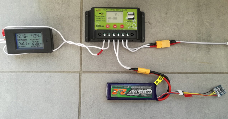
Connecting the controller is quite simple, it has only 3 connectors - for the solar panel, the load and the battery, respectively. As a load in my case, a 12V LED strip was connected, the battery is still the same test one with Hobbyking. Also on the controller there are 2 USB-connectors from which you can charge various devices.
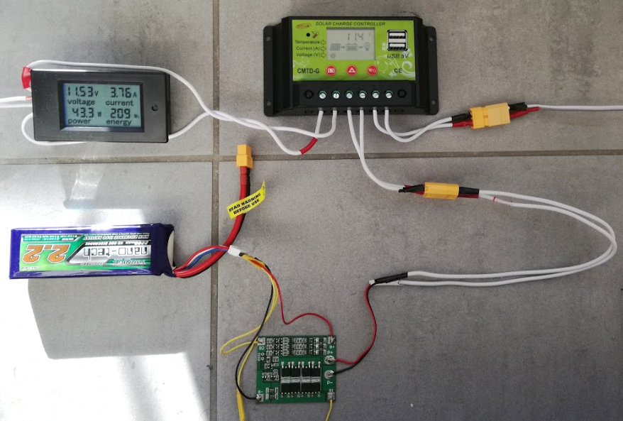
Everything together looked like this:
Before using the controller, it must be configured. The controllers of this model are sold in different versions for different types of batteries, the differences are likely only in the preset parameters. For my three-cell lithium battery (3S1P), I set the following values:
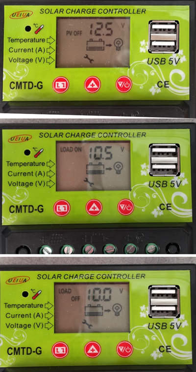
As you can see, the charge disconnect voltage (PV OFF) is set to 12.5V (based on 4.2V, 12.6 could be put per cell, but a small undercharging has a positive effect on the number of battery cycles). The next 2 parameters are load disconnection, in my case it is set to 10V, and re-enable the charge to 10.5V. The minimum value could be set lower, to 9.6V, a small margin was left for the controller itself, which is powered by the same battery.
With the discharge of problems was not expected. The battery charge was enough to charge the tablet, the LED strip also burned, and at a threshold voltage of 10V, the tape went out - the controller disconnected the load so as not to discharge the battery below a predetermined threshold.
But with the charge, everything went wrong. At first, everything was fine, and the maximum wattmeter power was about 50W, which is quite good. But towards the end of the charge, the tape connected as a load began to flicker strongly. The reason is clear and without an oscilloscope - the two BMS are not very friendly with each other. As soon as the voltage on one of the cells reaches the threshold, the BMS turns off the battery, which causes the load and the controller to turn off, then the process repeats. And considering that the threshold voltages are already set in the controller, the second protection card is not needed at all.
I had to go back to plan “B” - put only the balance board on the battery, leaving the charge control to the controller. The 3S balance board looks like this:
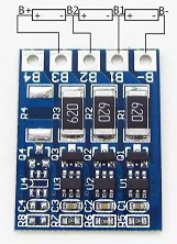
The bonus of this balancer is also in the fact that it is 2 times cheaper.
The design turned out to be even simpler and more beautiful - the balancer took its "legitimate" place on the balancing connector of the battery, the battery is connected to the controller through the power connector.
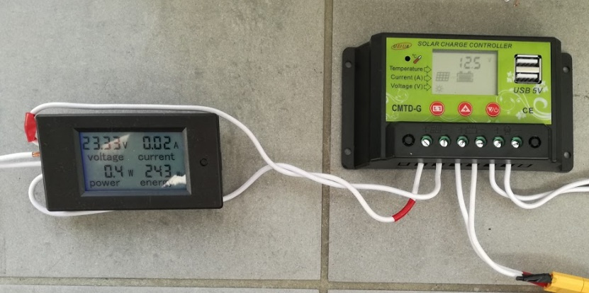
All together looks like this:
No more surprises there. When the voltage on the battery rose to 12.5V, the power consumed from the panels dropped to almost zero and the voltage increased to the maximum “idle” (22V), i.e. the charge no longer goes.
The voltage on the 3 cells of the battery at the end of the charge was 4.16V, 4.16V and 4.16V, which is a total of 12.48V, there are no complaints about the charge control, as well as the balancer.
The system works, almost as expected. During the day, electricity can accumulate, in the evening it can be used. In the final version, the battery will be replaced by a block of 18650 cells, which were already described in the previous section. The battery capacity can be increased up to 20 Ah, more for the balcony system is already redundant. If you buy another balancer, you can use LiFePo4 batteries, it is enough to set the required voltage thresholds in the controller. However, in my case, there is probably no point in this - the cost of LiFePo4 for 10-20 Ah is $ 80-100, which is already comparable to the cost of the Grid Tie controller, which I am going to test in the future.
Continued in the next part .
Still exclusively for tests (it is clear that there is no economic sense in this) a 12V ionistor battery was ordered, since prices are falling and now they are relatively cheap. It will be interesting to check how long their charge is. Stay tuned.
Note : The Hobbyking battery shown in the photo was supplied exclusively for the test. These batteries have not been tested for permanent use in such systems, nor are they recommended to be left unattended.
More or less, the final version of the battery looks like this:

These are 12 cells 18650, connected in groups in parallel by 4. The approximate battery capacity is about 12 hours, this is enough for charging various gadgets and for evening lighting of the room with LED tape. The battery uses the elements of Panasonic, the same as in cars Tesla S, the reliability of these cells can be considered quite good.
For those who want to watch the video version, the video is uploaded to youtube .
In the previous part , the operation of the BMS board was examined and verified, ensuring the correct charge of the lithium-ion battery. The Chinese mail finally delivered the Solar charge controller, so it's time to test it.
')
Test results under the cut.
Solar charge controller
This device is basic throughout the system - it is the controller that provides the interaction of all components - the solar panel, the load and the battery (it is needed only if we want to store energy in the battery, if we give energy directly to the electricity grid, we need a different type of grid tie controller).
There are quite a lot of controllers for small currents (10-20A) on the market, but since In our case, a lithium battery is used instead of a lead one, then we need to choose a controller with adjustable parameters. A controller was purchased, as in the photo, the issue price from $ 13 on eBay to $ 20-30, depending on the greed of local sellers. The controller is proudly called the “Intelligent PWM Solar Panel Charge Controller”, although in fact all its “intelligence” is the ability to set charge and discharge thresholds, and it is not structurally very different from the usual DC-DC converter.
Connecting the controller is quite simple, it has only 3 connectors - for the solar panel, the load and the battery, respectively. As a load in my case, a 12V LED strip was connected, the battery is still the same test one with Hobbyking. Also on the controller there are 2 USB-connectors from which you can charge various devices.
Everything together looked like this:
Before using the controller, it must be configured. The controllers of this model are sold in different versions for different types of batteries, the differences are likely only in the preset parameters. For my three-cell lithium battery (3S1P), I set the following values:
As you can see, the charge disconnect voltage (PV OFF) is set to 12.5V (based on 4.2V, 12.6 could be put per cell, but a small undercharging has a positive effect on the number of battery cycles). The next 2 parameters are load disconnection, in my case it is set to 10V, and re-enable the charge to 10.5V. The minimum value could be set lower, to 9.6V, a small margin was left for the controller itself, which is powered by the same battery.
Testing
With the discharge of problems was not expected. The battery charge was enough to charge the tablet, the LED strip also burned, and at a threshold voltage of 10V, the tape went out - the controller disconnected the load so as not to discharge the battery below a predetermined threshold.
But with the charge, everything went wrong. At first, everything was fine, and the maximum wattmeter power was about 50W, which is quite good. But towards the end of the charge, the tape connected as a load began to flicker strongly. The reason is clear and without an oscilloscope - the two BMS are not very friendly with each other. As soon as the voltage on one of the cells reaches the threshold, the BMS turns off the battery, which causes the load and the controller to turn off, then the process repeats. And considering that the threshold voltages are already set in the controller, the second protection card is not needed at all.
I had to go back to plan “B” - put only the balance board on the battery, leaving the charge control to the controller. The 3S balance board looks like this:
The bonus of this balancer is also in the fact that it is 2 times cheaper.
The design turned out to be even simpler and more beautiful - the balancer took its "legitimate" place on the balancing connector of the battery, the battery is connected to the controller through the power connector.
All together looks like this:
No more surprises there. When the voltage on the battery rose to 12.5V, the power consumed from the panels dropped to almost zero and the voltage increased to the maximum “idle” (22V), i.e. the charge no longer goes.
The voltage on the 3 cells of the battery at the end of the charge was 4.16V, 4.16V and 4.16V, which is a total of 12.48V, there are no complaints about the charge control, as well as the balancer.
Conclusion
The system works, almost as expected. During the day, electricity can accumulate, in the evening it can be used. In the final version, the battery will be replaced by a block of 18650 cells, which were already described in the previous section. The battery capacity can be increased up to 20 Ah, more for the balcony system is already redundant. If you buy another balancer, you can use LiFePo4 batteries, it is enough to set the required voltage thresholds in the controller. However, in my case, there is probably no point in this - the cost of LiFePo4 for 10-20 Ah is $ 80-100, which is already comparable to the cost of the Grid Tie controller, which I am going to test in the future.
Continued in the next part .
Still exclusively for tests (it is clear that there is no economic sense in this) a 12V ionistor battery was ordered, since prices are falling and now they are relatively cheap. It will be interesting to check how long their charge is. Stay tuned.
Note : The Hobbyking battery shown in the photo was supplied exclusively for the test. These batteries have not been tested for permanent use in such systems, nor are they recommended to be left unattended.
More or less, the final version of the battery looks like this:
These are 12 cells 18650, connected in groups in parallel by 4. The approximate battery capacity is about 12 hours, this is enough for charging various gadgets and for evening lighting of the room with LED tape. The battery uses the elements of Panasonic, the same as in cars Tesla S, the reliability of these cells can be considered quite good.
For those who want to watch the video version, the video is uploaded to youtube .
Source: https://habr.com/ru/post/404035/
All Articles