We manage the house through Telegram
Currently, smart home control systems are becoming increasingly popular. A centralized interface that manages devices throughout your home helps save time and makes it much more efficient to control your home. Realization of their vision of such systems is done by both famous brands: Apple, Amazon and Google, embedding them in their infrastructure, as well as craftsmen who assemble similar systems based on the Arduino platform.
Our goal was the following: to create a system that will be available on a large number of devices and will not be tied to any place. An excellent option for the implementation of management was a bot for the Telegram messenger. Telegram has applications on all major platforms, as well as a web version. Access to it can be obtained from anywhere, you just need to have an account.
From the modules we have chosen the following:
• Controlled RGB LED strip
• Controlled outlet
• Temperature sensor
• Light sensor (used to automatically turn on the light)
What we need
1. Raspberry Pi 3
A small but remote computer that does not need to be presented, its power will be enough for us with our head for these tasks. The third version is good presence of built-in Wi-Fi module, so we do not have to think about a third-party adapter.
2. Modules ESP8266
We need them 4 pieces. We used ESP-12F, but in general there is no difference: ESP-1 will be quite enough. Also ready NodeMCU boards will help save you time and effort.
3. LED strip
We took a managed RGB tape on the WS2812b controllers, although, however, any tape running on 5V and supported by the Arduino platform will do.
4. Temperature and lighting sensors
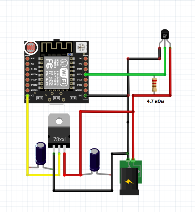
We used the BH1750 module to determine the illumination in the room and the DS18B20 for temperature. The main criteria were availability, support for the Arduino platform and the ability to work with 3.3V logic ESP8266.
5. Relay
The submodule MOD-1CH for Arduino can pass up to 10A of current and is controlled by 5V, we did not find any analogs for 3.3V, so we used a transistor in the key mode for control.
6. Telegram bot
Direct control of the entire system will be carried out using a Telegram bot running on Raspberry: this will allow the system to be easily accessible on any platform from anywhere in the world. Creating a bot for Telegram is quite simple, thanks to the advanced platform and the support of a large number of languages.
Thus, our entire system will look something like this:

Implementation
First we test the modules.
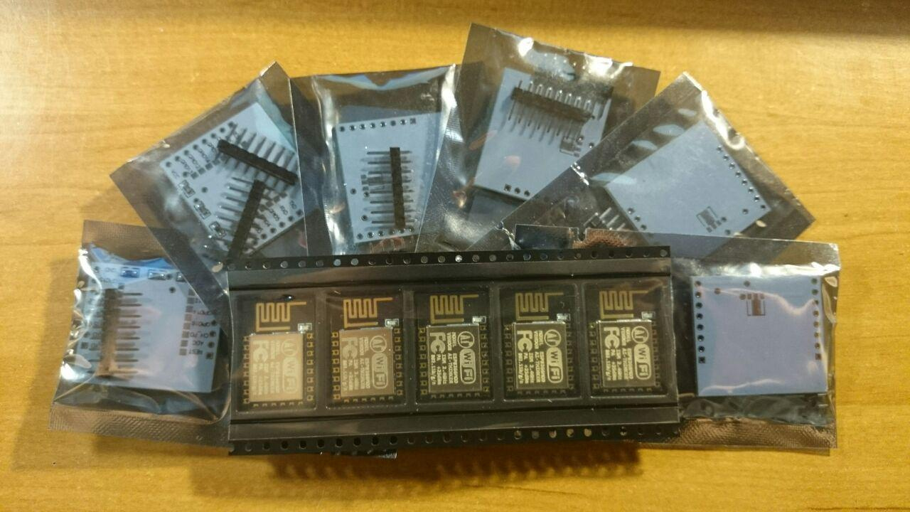
The finished printed circuit boards adapt the distance between the pins, which considerably facilitates the soldering, and also contains the necessary resistors connecting the CH_PD and GPIO2 pins to the Vcc.
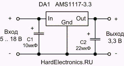
Unfortunately, the ESP8266 modules are powered and run on 3.3V, not 5, like the Arduino. You can convert voltage using a ready-to-use converter module, but you can also solder a circuit based on the AMS1117 linear stabilizer, as we did.
The next stage is programming.
Fortunately, the ESP8266 platform is supported by the Arduino IDE, which opens up many possibilities. To directly download the firmware to the module, we will use the Arduino Nano, but the same can be done through a regular USB-UART converter. Do not forget about the voltage difference between the Arduino and ESP.
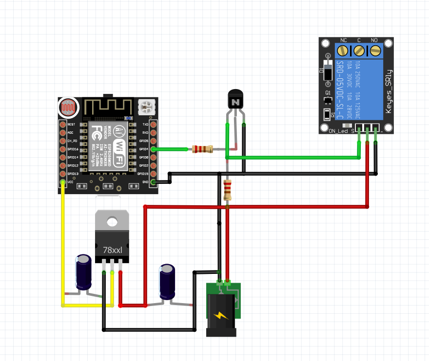
The scheme is as follows:
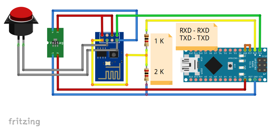
The button is needed in order to close the pin GPIO1 to GND when power is applied to the module and, thus, put it into programming mode.
Next, set up the Arduino IDE so that it understands ESP ( detailed instructions with all links ) and try to record a test sketch of a blinking LED.

After a successful blink, we proceeded to solder all the modules. With a temperature and lighting sensor, everything is pretty standard.
Temperatures:
Lighting:

But the ribbon and smart socket caused some difficulties.
A simple connection of the control input of the tape to the ESP did not result. It is not surprising, because WS2812b requires at least 70% of the VCC input (5x0.7 = 3.5) for the control input, and 3.3V board is not enough. However we found crutch An interesting way to run them without using a boost converter. If the diode requires at least 0.7xVcc to react to the signal and we cannot increase the level of this signal, then Vcc must be reduced! Yes, the LEDs will not burn so brightly, but we do not need to power the entire tape in this way; one diode is enough. Transmitting the signal further along the chain, the LED already uses the Vcc level to form a signal, which is quite enough for a “normal” LED. Thus, by connecting the first diode in the tape to power through a diode that “eats” about 0.6V, we get a perfectly working tape, which is directly controlled from our ESP8266 module. And we left the slightly dimmer first LED for debugging needs: display network connection status.
This is what happened:


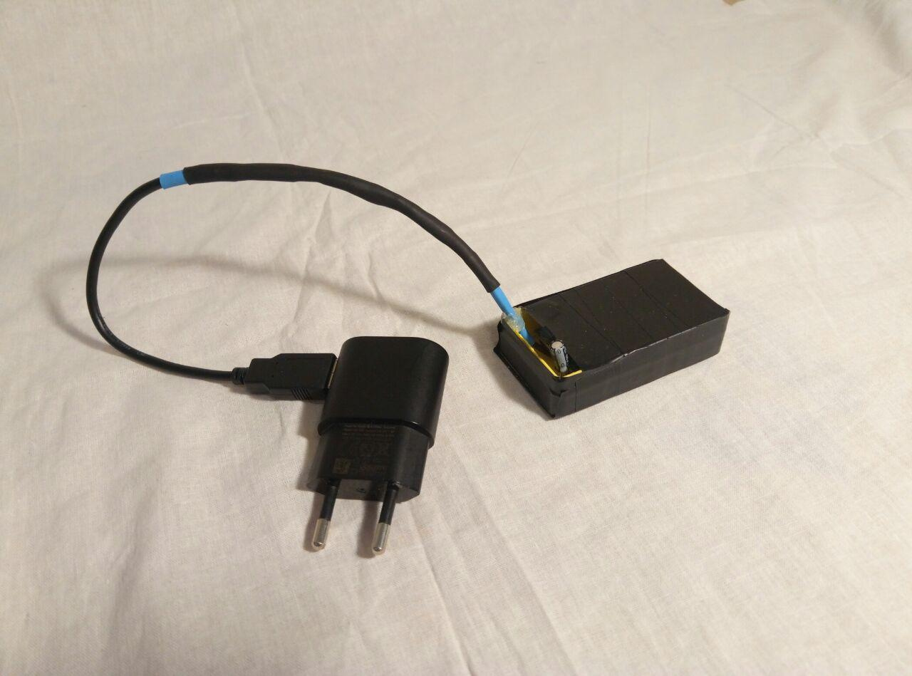
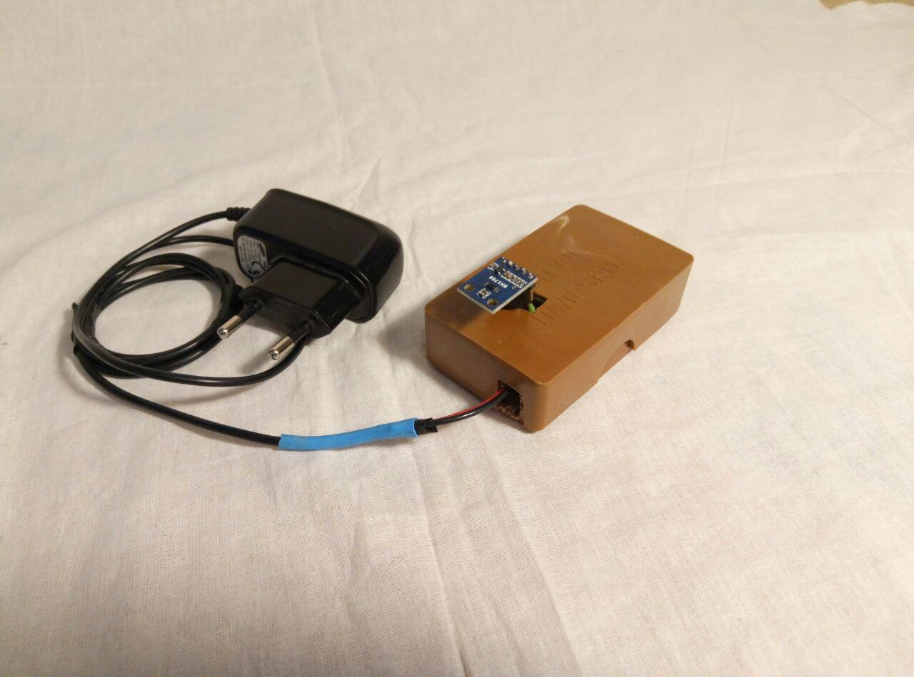
We wanted to place our smart socket completely in the case from the old socket with a timer. There should have got into: the ESP-12F itself, the power supply for it and the relay controlling the outlet. However, having placed a relay and a power supply there, we could not fit an ESP module there either. Therefore, I had to attach a small box from below.
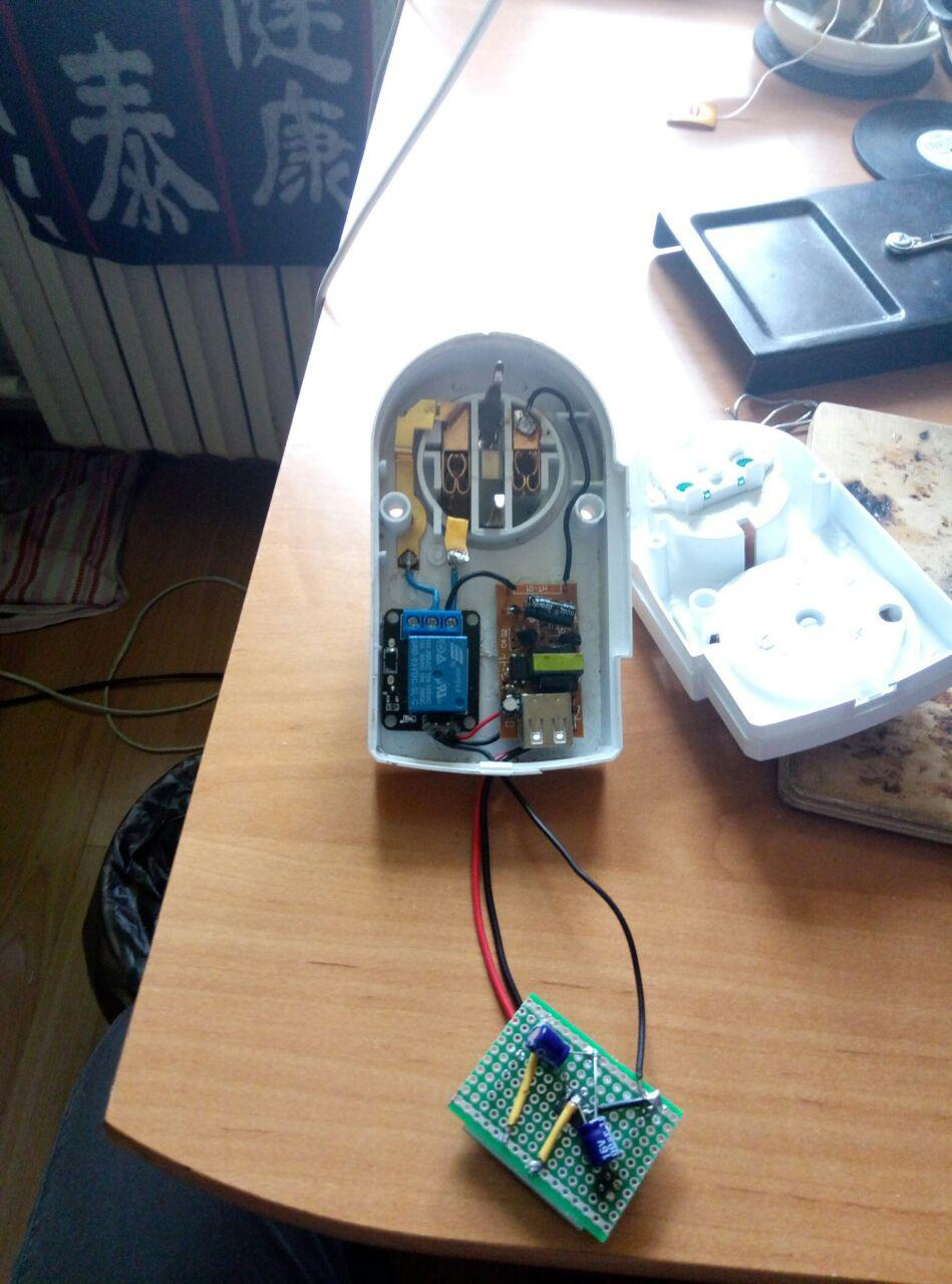
The result was not as elegant as we originally wanted, but it was a whole device that just had to be plugged into an outlet.

The next step was to configure Raspberry. The plan was this: our modules connect to the Wi-Fi access point, which is Raspberry, or rather, to its built-in Wi-Fi module. Telegram-bot was launched on Raspberry, which is located with all modules on the local network and can exchange http-requests with them without any problems. To the Internet it is all connected via Ethernet.
To implement this plan, we used two packages:
- hostapd - allows you to use the built-in wi-fi module as an access point
- dnsmasq - combines DHCP and DNS servers.
We tried to achieve relative independence of the code and devices, so all requests were made not to ip-addresses, but to names from the invented zone .sh (light.sh, socket.sh, etc.). To do this, we configured static ip-addresses for each module and added DNS records corresponding to the modules to these DNS addresses. The benefit of dnsmasq is very easy to configure ( detailed instructions for setting up this system ).
And, finally, directly bot.
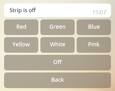
We wrote a bot in Python using the python-telegram-bot library. We have developed a button interface that simplifies operation, turning the device into a kind of remote control:

The source bot code can be explored here .
And so that no one would use it, we set the password protection.
Conclusion
Of course, we have not created any revolutionary system, there is a huge amount of more holistic and well thought-out implementations. The temperature and lighting modules could be made autonomous, since the ESP8266 has a special standby mode in which it consumes very little power. You could add lightweight user extensibility that does not require changing the source code and reconfiguring network connections and whatnot. However, the goal of this whole project was not at all that. First of all, we wanted to create a simple system that could well be created by anyone at home and would not require serious preparation and costs. And most importantly: we wanted to learn many things while we were doing this project. And if the practicality and functionality of our solution can be refined for a long time, then the knowledge we gained in the process of planning and implementing this system was definitely worth the effort.
')
Source: https://habr.com/ru/post/404009/
All Articles