Underwater GPS: continued
Today I want to tell you a little bit about what happened after the last article was published , where I told how the three of us made underwater GPS over the year.
We decided to estimate in real time the discrepancy between our underwater GPS and the present GPS. And not even just with GPS, but with combined GPS / GLONASS data. If we are interested in what we have done - welcome under the cut!
In general, we have somehow checked this, but in good “sea” conditions. Now, the idea arose to check everything in fact in a puddle. Here I must clarify that for any hydroacoustics, shallow water bodies are considered (and for good reason) the most difficult. Some manufacturers do not work at all in shallow water, saying that there is a terrible near-surface layer with dissolved gas and multiple reflections, etc.
In general, not far from us there is a wonderful puddle
')
This is how it looks from the shore:
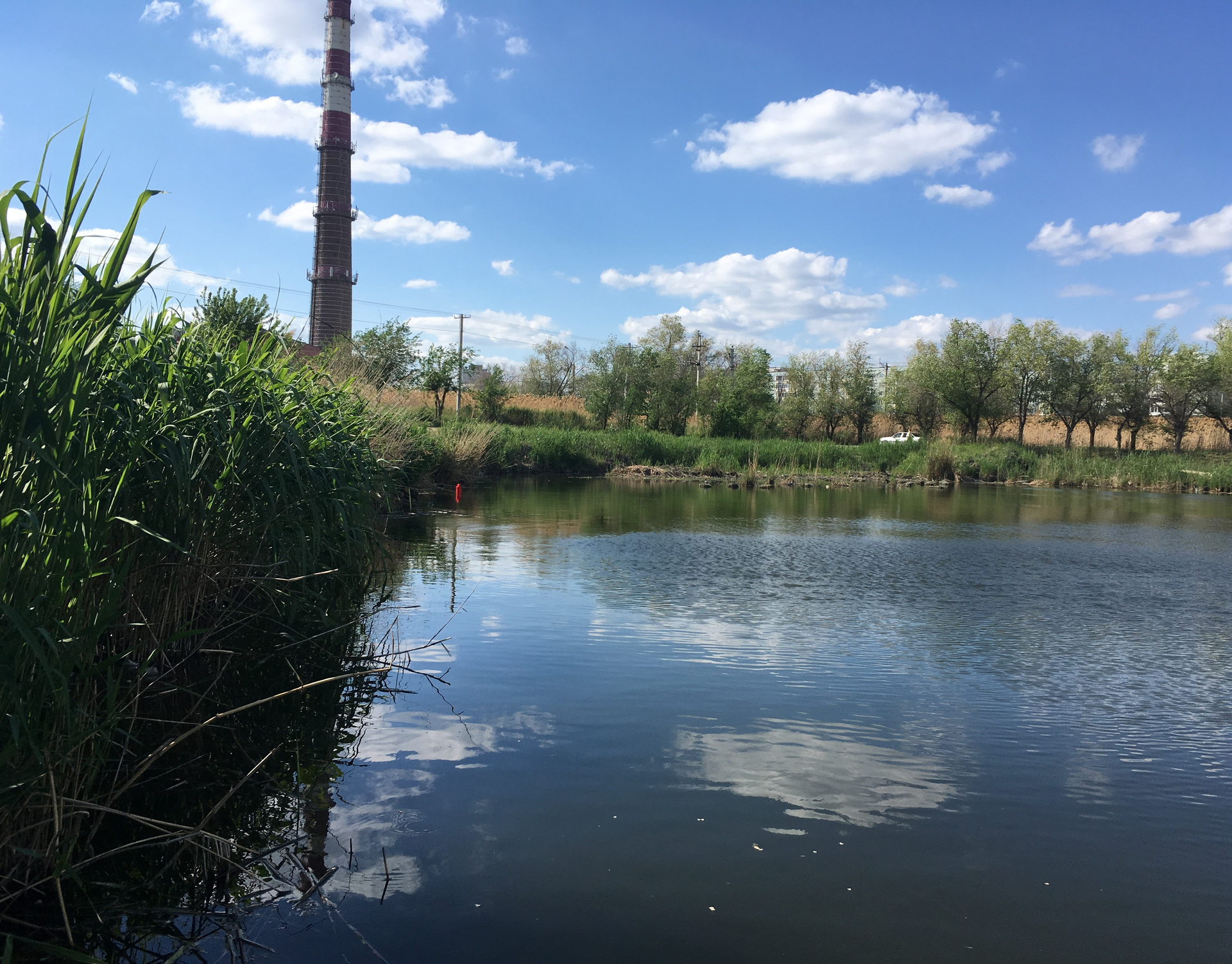
The maximum depth in it is about 2-2.5 m, that is, a shallower body of water, in which navigation may be required, is difficult to imagine.
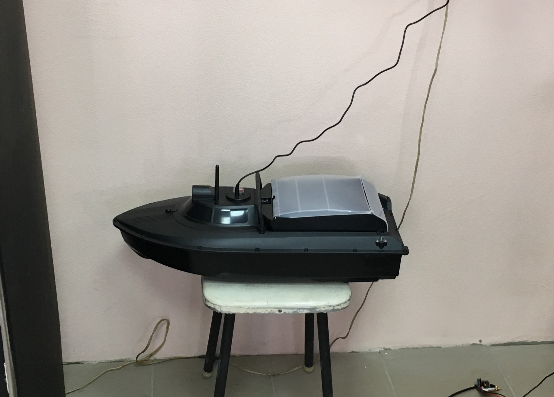
Especially for the upcoming experiments, a Chinese bait boat was purchased on the radio control - ideal for our purposes: it is enough (sometimes it seems to me that even too) a low-speed, roomy craft, which easily allows various modifications.
That is how the boat looked originally:
Then we made a number of improvements. Native electronics remained almost all and was only slightly moved, with the exception of the bait reset mechanism - as superfluous it was completely dismantled.
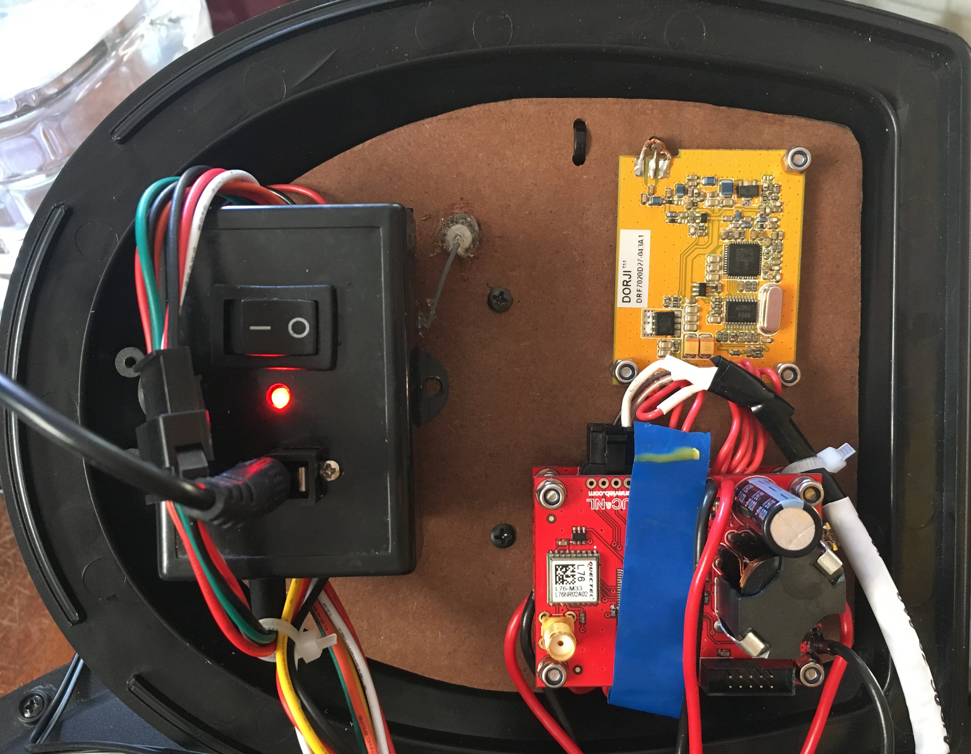
Additionally installed on the boat:
- a board with a GPS / GLONASS receiver of its own design (not visible in the photo - under the organalite panel);
- 433 MHz radio module DORJI + antenna to it;
- our board with a processor that parses the output data from the GPS module, acoustic navigation receiver and sends the whole thing over the radio;
- an additional lead battery of 1.5 A * h from which all of our consumers feed;
- Bulgin Bucaneer charging connector for it;
- toggle switch with a rubber cap (as on our buoys), including all our systems;
- a pair of simple cable entries through which the cable of the navigation receiver RedNODE is inserted into the boat and the cable of the acoustic emitter is output (used in another experiment).
The photo shows another board - this is just from another experiment.
As I told in the previous article, our underwater GPS is a long-base navigation system, and for its work on the pond, we need to install four floating buoys-repeater satellite navigation signal. This is the main minus of the long base - on the pond you still need to put something there, which means you need a boat. But this time we wanted to show how you can do everything exclusively from the shore.
Fortunately, there were four of us (yes, there are no more three of us!), And, according to the idea, everyone took a buoy with him and went to his point on the bank of the pond, where he put his buoy on a string from the shore (so as not to sail away - they did not take the boat) .
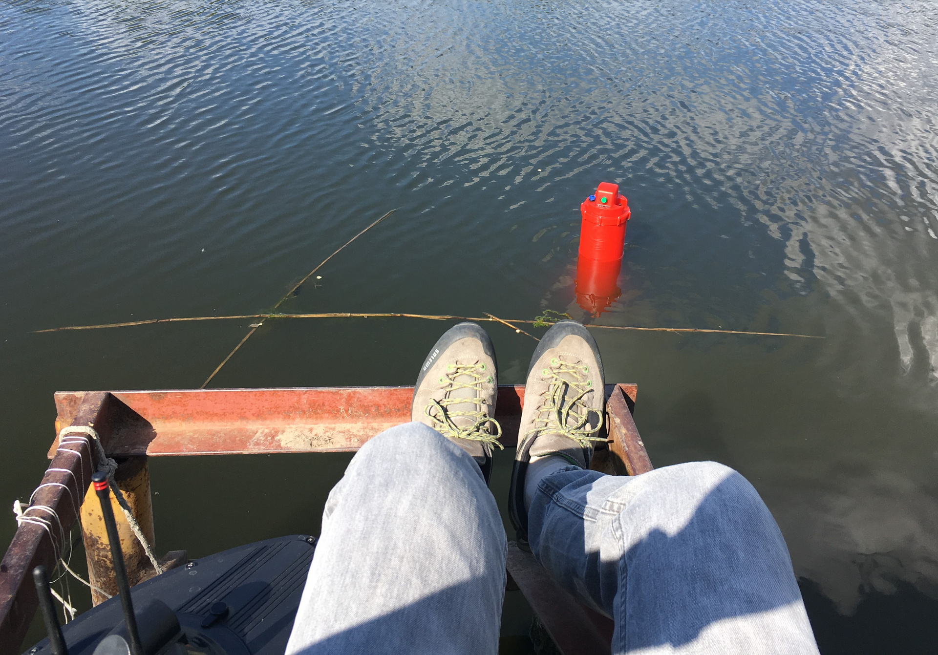
Here at my point (Buoy No. 4) it looked like this:
On the shore where I was located, there were two convenient approaches. My two colleagues on the opposite bank were less fortunate - there is just a fairly flat coast overgrown with reeds, trampled down here and there by fishermen. As a result, as will be seen from the location, the buoy No. 3 had to endure very far from the rest, simply because in that place it was quite difficult to approach the water.
The screenshot below shows how the buoys were arranged (decomposed) during the experiment:

By the way, looking ahead, I will say that the coordinates of the buoys are obtained from the navigation receiver, and not measured directly on land.
The photo shows very clearly that a bank is located to the left of the conventional line between the buoys No. 1 and No. 2. Such that a heron walks there on foot (she’s about a knee-deep there), which could not be photographed this time.
From my post, the opposite bank looks like in the next photo, and the person sitting on the left is ours, he keeps buoy No. 1 on the rope.
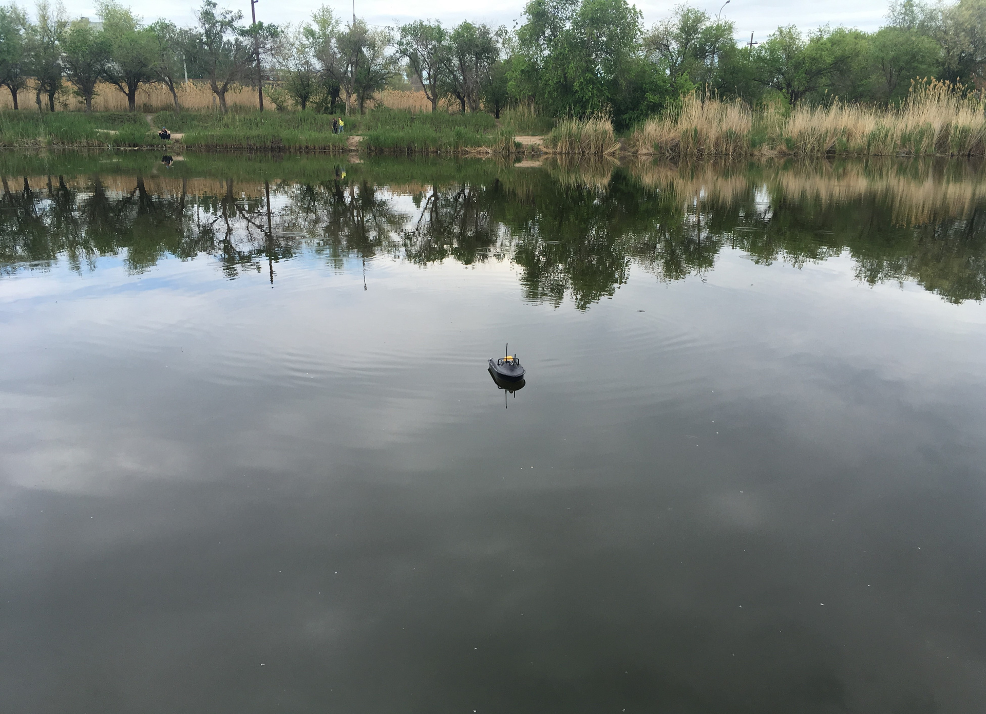
In the same photo you can see our boat in the process of sailing.
This is how it looks assembled next to one of our buoys:
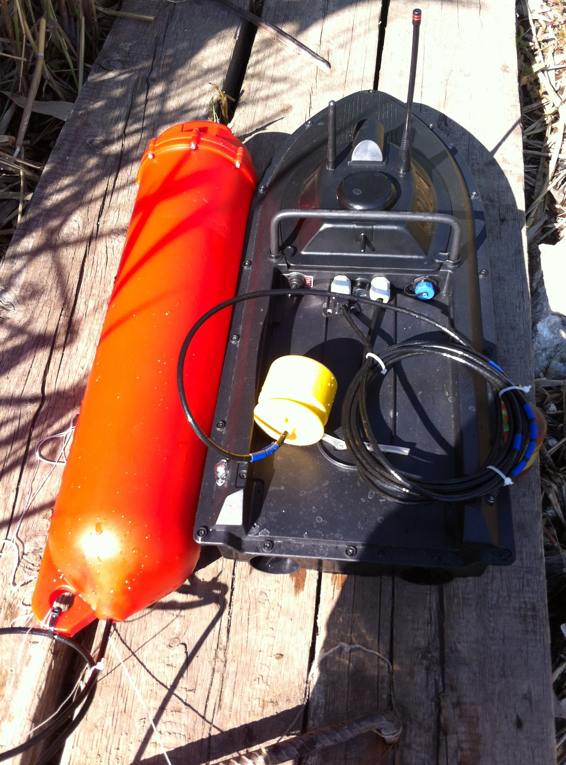
The cables of the buoys had to be shorter, pulling them to the load-carrying eye of the buoy with a nylon tie, otherwise the radiator simply turned out to be lying on a silty bottom. In the normal position, the distance from the water edge to the buoy acoustic transmitter is 1.5 meters. You can also see that the acoustic navigation receiver is mounted on a sufficiently long cable. Its length is 1.5 meters, remember this, in the future it will allow to explain some features of the results.
The influence of freely dangling cylinder on the movement of the boat is very significant. In fact, the turning radius of an already indecent 3-4 meter became terrifying: on calm water, you need 10-15 meters to turn. My attempts to keep the boat on the course with a light side wind will be visible on the resulting tracks.
Speaking of tracks. Before the experiment, there was no 100% certainty that the system would, in principle, work adequately in such conditions. But nevertheless, I saw the first point on the screen almost a minute after the receiver was immersed in water.
I saw it on the screen of our technology application, something like this:
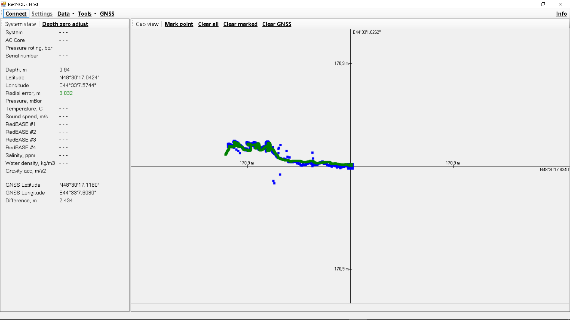
The track from the GPS / GLONASS receiver is displayed in green, and the track from the acoustic receiver is displayed in blue. The bottom line in the left pane displays the difference in meters between the current reading according to the GPS / GLONASS and the speaker navigation system. I’ll say right away that the hastily collected “combiner” of data selected only a part of the information that the navigation receiver transmits and many fields remained empty.
And finally, the resulting tracks in all their glory:
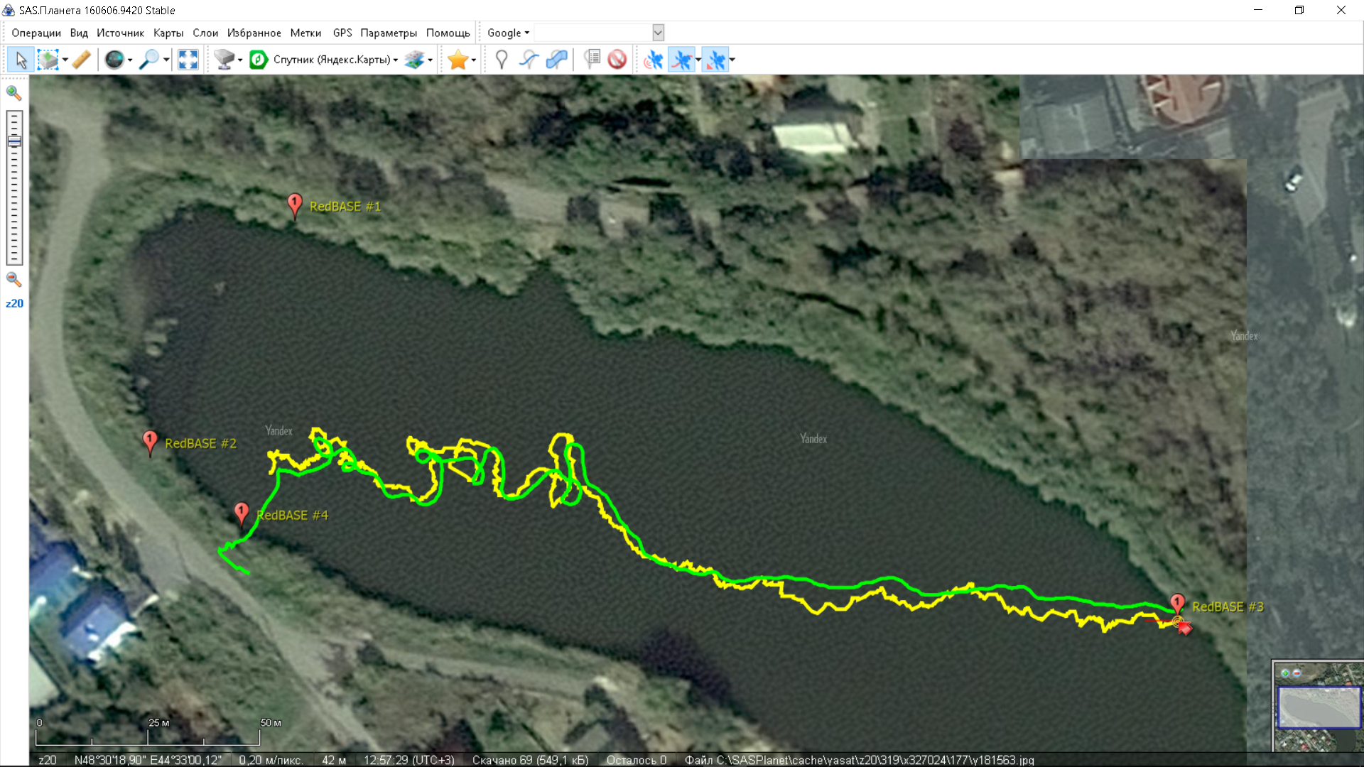
The maximum difference between the trajectories in different places is about 3 meters, which is explained, firstly, by the fact that the acoustic system is still much more influenced by the motion of the positioned object on the accuracy of the calculated position, simply because between receiving signals from buoys she has enough time to move, and, secondly, the fact that the acoustic navigation receiver dangled on a 1.5-meter cable behind the boat with all the ensuing consequences.
Very characteristic look repetitions of the trajectory with some delay, obtained with the help of an acoustic navigation system, in those areas where the boat was intensively maneuvering.
In general, we did not plan such a long hike tritely afraid of losing the boat in the reeds, but at some point I realized that I could hardly safely deploy the ship and decided to send it in the wind, which almost brought it to our buoy No. 3, where it is safely and caught my colleague.
What do we have as a result of the experiment?
- the system works in a reservoir monstrous from the point of view of hydrology
- accuracy is comparable with accuracy of ground GPS
- does not require any calibration
- integrates as easily as a conventional GPS receiver
- deployment does not take much time (in our case, three buoys were in the water in 5 minutes, and the fourth in 10 more, and then, all this time was spent on getting around the pond)
It is inconvenient to show the tracks in sufficient detail with the help of a picture, so I lay out the tracks separately so that all who are interested can analyze them:
tracks redwave 12-05-2017
Thanks for attention.
"And that's it for today!" (C)
Attention! Update! As it turned out, if you follow the link to our puddle , you can see that the drone was supposedly flying just above the site of our experiments at the time of the survey:

We decided to estimate in real time the discrepancy between our underwater GPS and the present GPS. And not even just with GPS, but with combined GPS / GLONASS data. If we are interested in what we have done - welcome under the cut!
In general, we have somehow checked this, but in good “sea” conditions. Now, the idea arose to check everything in fact in a puddle. Here I must clarify that for any hydroacoustics, shallow water bodies are considered (and for good reason) the most difficult. Some manufacturers do not work at all in shallow water, saying that there is a terrible near-surface layer with dissolved gas and multiple reflections, etc.
In general, not far from us there is a wonderful puddle
')
This is how it looks from the shore:
The maximum depth in it is about 2-2.5 m, that is, a shallower body of water, in which navigation may be required, is difficult to imagine.
Especially for the upcoming experiments, a Chinese bait boat was purchased on the radio control - ideal for our purposes: it is enough (sometimes it seems to me that even too) a low-speed, roomy craft, which easily allows various modifications.
That is how the boat looked originally:
Then we made a number of improvements. Native electronics remained almost all and was only slightly moved, with the exception of the bait reset mechanism - as superfluous it was completely dismantled.
Additionally installed on the boat:
- a board with a GPS / GLONASS receiver of its own design (not visible in the photo - under the organalite panel);
- 433 MHz radio module DORJI + antenna to it;
- our board with a processor that parses the output data from the GPS module, acoustic navigation receiver and sends the whole thing over the radio;
- an additional lead battery of 1.5 A * h from which all of our consumers feed;
- Bulgin Bucaneer charging connector for it;
- toggle switch with a rubber cap (as on our buoys), including all our systems;
- a pair of simple cable entries through which the cable of the navigation receiver RedNODE is inserted into the boat and the cable of the acoustic emitter is output (used in another experiment).
The photo shows another board - this is just from another experiment.
As I told in the previous article, our underwater GPS is a long-base navigation system, and for its work on the pond, we need to install four floating buoys-repeater satellite navigation signal. This is the main minus of the long base - on the pond you still need to put something there, which means you need a boat. But this time we wanted to show how you can do everything exclusively from the shore.
Fortunately, there were four of us (yes, there are no more three of us!), And, according to the idea, everyone took a buoy with him and went to his point on the bank of the pond, where he put his buoy on a string from the shore (so as not to sail away - they did not take the boat) .
Here at my point (Buoy No. 4) it looked like this:
On the shore where I was located, there were two convenient approaches. My two colleagues on the opposite bank were less fortunate - there is just a fairly flat coast overgrown with reeds, trampled down here and there by fishermen. As a result, as will be seen from the location, the buoy No. 3 had to endure very far from the rest, simply because in that place it was quite difficult to approach the water.
The screenshot below shows how the buoys were arranged (decomposed) during the experiment:
By the way, looking ahead, I will say that the coordinates of the buoys are obtained from the navigation receiver, and not measured directly on land.
The photo shows very clearly that a bank is located to the left of the conventional line between the buoys No. 1 and No. 2. Such that a heron walks there on foot (she’s about a knee-deep there), which could not be photographed this time.
From my post, the opposite bank looks like in the next photo, and the person sitting on the left is ours, he keeps buoy No. 1 on the rope.
In the same photo you can see our boat in the process of sailing.
This is how it looks assembled next to one of our buoys:
The cables of the buoys had to be shorter, pulling them to the load-carrying eye of the buoy with a nylon tie, otherwise the radiator simply turned out to be lying on a silty bottom. In the normal position, the distance from the water edge to the buoy acoustic transmitter is 1.5 meters. You can also see that the acoustic navigation receiver is mounted on a sufficiently long cable. Its length is 1.5 meters, remember this, in the future it will allow to explain some features of the results.
The influence of freely dangling cylinder on the movement of the boat is very significant. In fact, the turning radius of an already indecent 3-4 meter became terrifying: on calm water, you need 10-15 meters to turn. My attempts to keep the boat on the course with a light side wind will be visible on the resulting tracks.
Speaking of tracks. Before the experiment, there was no 100% certainty that the system would, in principle, work adequately in such conditions. But nevertheless, I saw the first point on the screen almost a minute after the receiver was immersed in water.
I saw it on the screen of our technology application, something like this:
The track from the GPS / GLONASS receiver is displayed in green, and the track from the acoustic receiver is displayed in blue. The bottom line in the left pane displays the difference in meters between the current reading according to the GPS / GLONASS and the speaker navigation system. I’ll say right away that the hastily collected “combiner” of data selected only a part of the information that the navigation receiver transmits and many fields remained empty.
And finally, the resulting tracks in all their glory:
The maximum difference between the trajectories in different places is about 3 meters, which is explained, firstly, by the fact that the acoustic system is still much more influenced by the motion of the positioned object on the accuracy of the calculated position, simply because between receiving signals from buoys she has enough time to move, and, secondly, the fact that the acoustic navigation receiver dangled on a 1.5-meter cable behind the boat with all the ensuing consequences.
Very characteristic look repetitions of the trajectory with some delay, obtained with the help of an acoustic navigation system, in those areas where the boat was intensively maneuvering.
In general, we did not plan such a long hike tritely afraid of losing the boat in the reeds, but at some point I realized that I could hardly safely deploy the ship and decided to send it in the wind, which almost brought it to our buoy No. 3, where it is safely and caught my colleague.
What do we have as a result of the experiment?
- the system works in a reservoir monstrous from the point of view of hydrology
- accuracy is comparable with accuracy of ground GPS
- does not require any calibration
- integrates as easily as a conventional GPS receiver
- deployment does not take much time (in our case, three buoys were in the water in 5 minutes, and the fourth in 10 more, and then, all this time was spent on getting around the pond)
It is inconvenient to show the tracks in sufficient detail with the help of a picture, so I lay out the tracks separately so that all who are interested can analyze them:
tracks redwave 12-05-2017
Thanks for attention.
"And that's it for today!" (C)
Attention! Update! As it turned out, if you follow the link to our puddle , you can see that the drone was supposedly flying just above the site of our experiments at the time of the survey:
Source: https://habr.com/ru/post/403891/
All Articles