Balcony Solar Panel: Battery and BMS Testing
Hello geektimes! In the previous part we briefly talked about the components necessary for the accumulation of energy from the solar battery, now we will move on to testing the components. I wanted to test both main parts - the solar panel controller (Solar charge controller) and the BMS (Battery Management System), but the speed of the mail operation made its adjustments. Therefore, we begin only with BMS, and the rest of the details had to be taken from those that were found at hand.
What happened, the details under the cut.
As mentioned earlier, the Battery Management System is used to work with the battery - it is a board that does several useful functions at once:
- provides uniform charge of cells,
- protects the battery from overcharging, which is extremely harmful and even fire hazardous for lithium batteries,
- protects the battery from overdischarge, which is also harmful to the battery, although not flammable.
')
In my case, the 18650 Protection Balance Board was ordered (again, it is important to note the presence of both protection and balance components on the board, there are boards where there is one thing), which looks like this:

The cost of the fee is $ 8, and some readers have expressed doubts about the quality of its work. This we also check. In the previous part there were questions, so once again I will explain that the 3 “batteries” on the diagram are shown conditionally, each cell in real life may consist of several parallel (as is actually done in laptops).
To connect the BMS in the old stocks were missing components.
1) Lithium-ion 3S1P battery with Hobbyking capacity 2.1Ah:
This is not the 18650 form factor, but the cell chemistry is the same, so there is essentially no difference.
2) Step-down dc-dc converter:
With this converter, the voltage will be applied to the BMS. The power of the converter is 15W, so by and large, it does not fit the 100-watt panel. However, the weather was overcast, so that the test will come down. The maximum value for LiPo 4.2 * 3 = 12.6V was set on the converter.
The correct LiPo charge algorithm looks like this:
In the first phase, the battery is charged with a constant current (CC, constant current) until it reaches a voltage of 4.2V per cell. Then this voltage is maintained by the charger (CV mode, constant voltage), until the charge current drops to the minimum value.
Our charge algorithm will be “slightly” more simplified. Only the first phase of the SS remains, in which the current will only conditionally be constant, since current from solar panels is constantly changing. However, there is nothing wrong with this; on the contrary, charging with lower currents prolongs the life of the battery. The absence of the second phase of the CV will only lead to the fact that the battery will be charged at about 80%, but this will not worsen other battery parameters. Harm to the battery from undercharging is also not, rather the opposite.
For testing, a lithium-ion battery was taken, the cell voltage was different, and was respectively 3.13, 3.47 and 3.44V. "On the knee" all the above components were assembled and connected together.
Cloud cover was variable, and even with intermittent rain. The power received from the solar panel ranged from 2 to 18W. There were concerns about the operation of the converter, which was very warm to the touch, but in fact its temperature turned out to be quite low.

BMS did not warm up at all, the elements were only 1-2 degrees warmer than the background. The battery was also cold.
Finally, somewhere in 3.5 hours the voltage on the indicator reached 12.5V, and the current consumed became zero - BMS disconnected the battery from the charge. For those who did not believe in the possibility of BMS operation for $ 8 - the voltage measured on the cells by a multimeter was 4.18, 4.18 and 4.18V. This is slightly less than 4.2 V, but it fits into the declared for LiPo tolerance +/– 50mV / cell.
For discharge, a piece of LED strip was connected to the battery, also through BMS, as “evening” lighting:
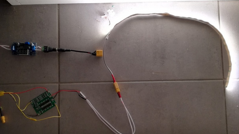
Of course, a 12V LED lamp would be more convenient, but I don't have one. The tape luminescent about 2.5 hours in the evening, as a background light. In the morning, a smart phone was turned on for charging to the battery via dc-dc converter with built-in USB output:
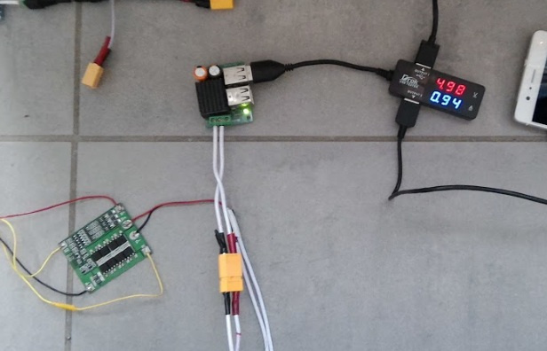
The remaining charge in the battery was enough to charge the smartphone from 15% to 75%, then BMS disconnected the battery. The voltage remaining on the battery cells after disconnection was 3.18, 3.51 and 3.45V, respectively, which again complies with the norms. As you can see, the BMS disconnected the battery as soon as the voltage on at least one cell dropped below normal.
We can say that BMS works as expected - it aligns the voltage of the cells during charging, and does not allow deep discharge. However, taking into account the parameters stated by the manufacturer “3S 12.6V 25A”, it would be strange if it did not work - the current from the solar panels is noticeably less (even taking into account the likely marketing and “Chinese watts”).
Even in such a “test” form, the system is already working, allowing us to accumulate solar energy during the day and use it in the evening. The peak power per watt meter was about 30W with a current of about 2A, you can roughly estimate that in half a day you can charge a 12Ah battery, i.e. with some reserve, there will be enough batteries for 20 Ah (again, there is not a lot of batteries, on cloudy days the output is less). This is enough for evening lighting with a 1-3W LED-lamp and for charging all gadgets.
A battery from rc-models with Hobbyking was delivered as a temporary solution, exclusively for the test. These batteries have not been tested in continuous mode, so I cannot recommend it for purchase in this capacity. At the same time, there were no problems in her work either - discharge currents 1-2A for these batteries are simply ridiculous (for comparison, in a quadcopter during flight the current is 20-25A).
The next part will cover Solar Charge Controller, and how it all works together. Stay tuned.
What happened, the details under the cut.
Battery charge
As mentioned earlier, the Battery Management System is used to work with the battery - it is a board that does several useful functions at once:
- provides uniform charge of cells,
- protects the battery from overcharging, which is extremely harmful and even fire hazardous for lithium batteries,
- protects the battery from overdischarge, which is also harmful to the battery, although not flammable.
')
In my case, the 18650 Protection Balance Board was ordered (again, it is important to note the presence of both protection and balance components on the board, there are boards where there is one thing), which looks like this:
The cost of the fee is $ 8, and some readers have expressed doubts about the quality of its work. This we also check. In the previous part there were questions, so once again I will explain that the 3 “batteries” on the diagram are shown conditionally, each cell in real life may consist of several parallel (as is actually done in laptops).
Components
To connect the BMS in the old stocks were missing components.
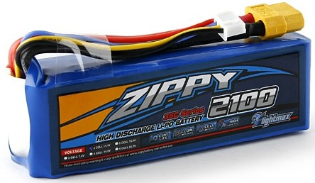
1) Lithium-ion 3S1P battery with Hobbyking capacity 2.1Ah:
This is not the 18650 form factor, but the cell chemistry is the same, so there is essentially no difference.
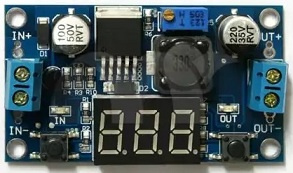
2) Step-down dc-dc converter:
With this converter, the voltage will be applied to the BMS. The power of the converter is 15W, so by and large, it does not fit the 100-watt panel. However, the weather was overcast, so that the test will come down. The maximum value for LiPo 4.2 * 3 = 12.6V was set on the converter.
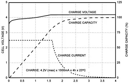
The correct LiPo charge algorithm looks like this:
In the first phase, the battery is charged with a constant current (CC, constant current) until it reaches a voltage of 4.2V per cell. Then this voltage is maintained by the charger (CV mode, constant voltage), until the charge current drops to the minimum value.
Our charge algorithm will be “slightly” more simplified. Only the first phase of the SS remains, in which the current will only conditionally be constant, since current from solar panels is constantly changing. However, there is nothing wrong with this; on the contrary, charging with lower currents prolongs the life of the battery. The absence of the second phase of the CV will only lead to the fact that the battery will be charged at about 80%, but this will not worsen other battery parameters. Harm to the battery from undercharging is also not, rather the opposite.
Charge
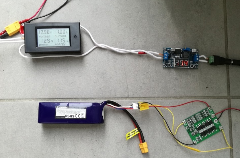
For testing, a lithium-ion battery was taken, the cell voltage was different, and was respectively 3.13, 3.47 and 3.44V. "On the knee" all the above components were assembled and connected together.
Cloud cover was variable, and even with intermittent rain. The power received from the solar panel ranged from 2 to 18W. There were concerns about the operation of the converter, which was very warm to the touch, but in fact its temperature turned out to be quite low.
BMS did not warm up at all, the elements were only 1-2 degrees warmer than the background. The battery was also cold.
Finally, somewhere in 3.5 hours the voltage on the indicator reached 12.5V, and the current consumed became zero - BMS disconnected the battery from the charge. For those who did not believe in the possibility of BMS operation for $ 8 - the voltage measured on the cells by a multimeter was 4.18, 4.18 and 4.18V. This is slightly less than 4.2 V, but it fits into the declared for LiPo tolerance +/– 50mV / cell.
Discharge
For discharge, a piece of LED strip was connected to the battery, also through BMS, as “evening” lighting:
Of course, a 12V LED lamp would be more convenient, but I don't have one. The tape luminescent about 2.5 hours in the evening, as a background light. In the morning, a smart phone was turned on for charging to the battery via dc-dc converter with built-in USB output:
The remaining charge in the battery was enough to charge the smartphone from 15% to 75%, then BMS disconnected the battery. The voltage remaining on the battery cells after disconnection was 3.18, 3.51 and 3.45V, respectively, which again complies with the norms. As you can see, the BMS disconnected the battery as soon as the voltage on at least one cell dropped below normal.
Conclusion
We can say that BMS works as expected - it aligns the voltage of the cells during charging, and does not allow deep discharge. However, taking into account the parameters stated by the manufacturer “3S 12.6V 25A”, it would be strange if it did not work - the current from the solar panels is noticeably less (even taking into account the likely marketing and “Chinese watts”).
Even in such a “test” form, the system is already working, allowing us to accumulate solar energy during the day and use it in the evening. The peak power per watt meter was about 30W with a current of about 2A, you can roughly estimate that in half a day you can charge a 12Ah battery, i.e. with some reserve, there will be enough batteries for 20 Ah (again, there is not a lot of batteries, on cloudy days the output is less). This is enough for evening lighting with a 1-3W LED-lamp and for charging all gadgets.
A battery from rc-models with Hobbyking was delivered as a temporary solution, exclusively for the test. These batteries have not been tested in continuous mode, so I cannot recommend it for purchase in this capacity. At the same time, there were no problems in her work either - discharge currents 1-2A for these batteries are simply ridiculous (for comparison, in a quadcopter during flight the current is 20-25A).
The next part will cover Solar Charge Controller, and how it all works together. Stay tuned.
Source: https://habr.com/ru/post/403873/
All Articles