Make Keyestudio GSM / GPRS Shield work through the Amperka library
I want to present a library to GSM / GPRS Shield for Arduino from Keyestudio. I bought this device because of the price. In China, it was almost 2 times cheaper than its counterpart from Amperki, and three times less than that of iAruino. The reason for writing this text is the lack of an acceptable library on Keyestudio website for working with it. Work through a set of AT-commands is not considered. Libraries for other similar devices in the direct did not fit. In any case, I could not get them to work.
I had to adapt, in my opinion, the most developed "Amperek" library for this board, and thus try to preserve the compatibility of the code written under the amperovsky shield.
Actually link to the library: github.com/andrewinc/keyestudio-gsm-gprs-shield
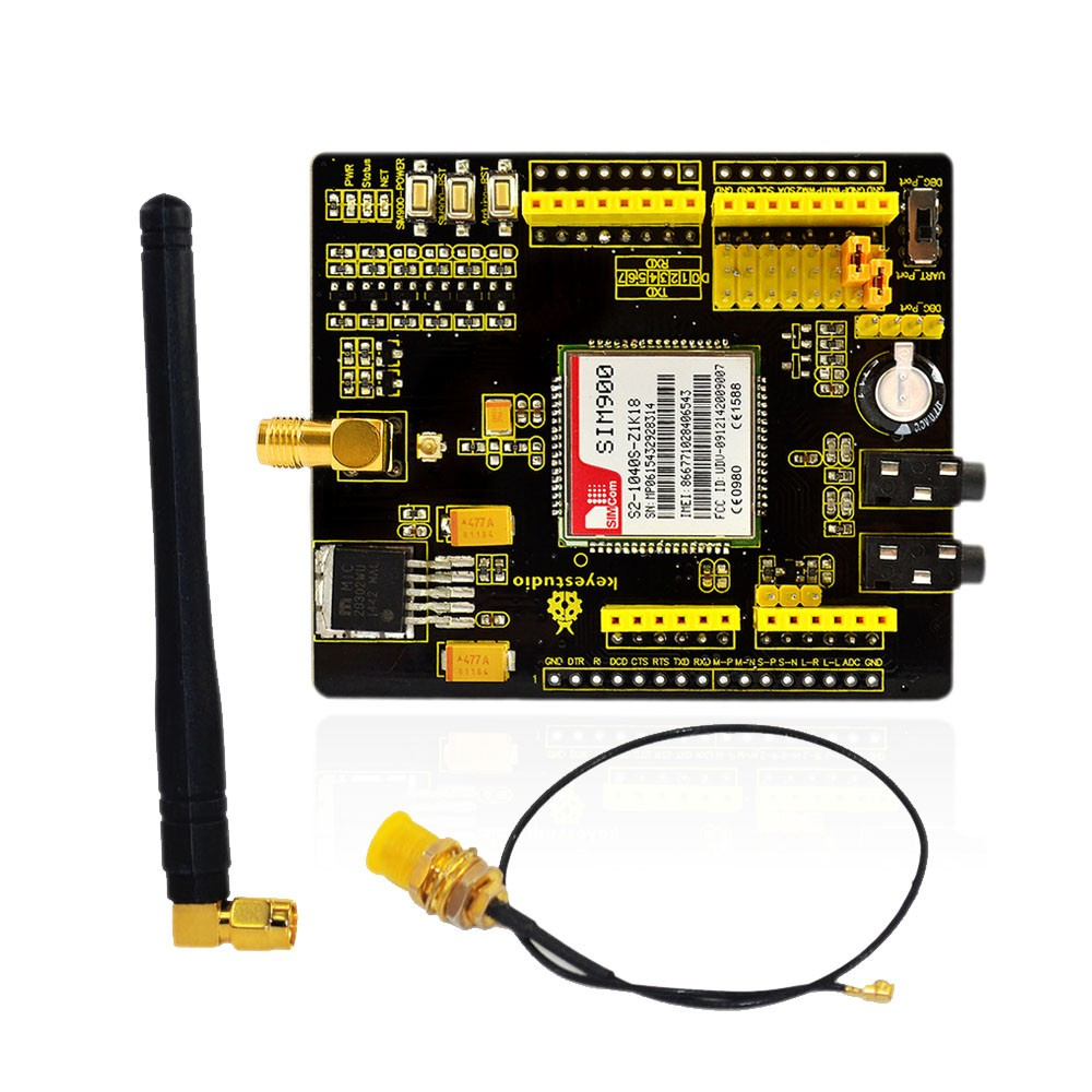
Ampere uses Sim900R chip in its shield, and here Sim900. The most important difference in the ST signal: it is in the source library and shield, but not in Keyestudio. Meanwhile, it would be clearly on or off the chip. But there is a button SIM900_Power, which led me to bad thoughts about the lack of software to enable the chip. Fortunately, they were wrong.
Pin 9 - controls the inclusion of the chip, the same substitute for the Power button on the amperkovskaya board is marked PK.
')
A small difference in the chip version did not affect its capabilities; in any case, I was able to initiate a call, send and receive an SMS using the examples provided in the library. I guess this is the main direction of using this shield.
The board communicates with Arduino via the UART-interface. For those who are not aware of the UART - these are the TX and RX pins. By TX - data follow from Arduino, and by RX - back.
There is also a switch “UART_Port - DBG_Port”, but I did not use this port. The switch remained in the "UART_Port".
The special feature of the board is that it does not work out of the box. If you pay attention to the state of the jumpers after opening the package (see photo above), you can see the connections TXD c 0 and RXD with 1. On the Arduino for TX and RX, the same pins are used. The problem is just that, because they are used to download the sketch, they are also used to exchange information through the Serial object, incl. and for debugging. When connecting Arduino with a shield, a conflict arises and the firmware fails.
It is known that Arduino UNO has only one Serial interface, but their whole family is, for example, Arduino Mega. Serial1 is associated with a pair of TX1 and RX1, similarly for Serial2 and Serial3.
For the use of Arduino UNO, it is reasonable to use software Serial. It is enough to connect the appropriate library, and create the object itself, specifying the pins of the Arduino to which TXD and RXD signals come from the shield:
In this example, TXD is connected to pin 6, and RXD is connected to 7.
Pin on / off the chip - 9, in contrast to the TX and RX, can not be switched to other outputs of the Arduino, in any case, the switches on the shield for this were not found.
To turn on the chip, you need to send a high signal to 9 pins, wait 1-3 seconds and send a low signal to it. Further, usually in the code you can see the wait in seconds 5-15. All this is reminiscent of the manipulation of the power button on the cell phone, and subsequently loading it and establishing communication with the network.
In the source library from Ampere there was feedback through the ST signal. Through it, in the process of switching on, the state was checked: whether the chip is on. Alas, in the absence of this signal, the methods of turning the chip on and off are similar to the twin brothers, since the shutter is also supplied with a 9 pin for shutdown. These methods were not combined into one because of the compatibility of the codeand because of the banal laziness .
The library itself is connected with the string:
After that, you can create an object based on the GPRSk class and transfer the same mySerial to the constructor or specify the hardware Serial1, Serial2, etc. Example:
The setup function typically initializes Serial and mySerial, however, if you do not plan to send debugging information to the Arduino IDE monitor, you can only get by initializing mySerial.
After that, the chip power supply is turned on using the gprs.powerOn () method and then gprs.init () is called, which returns true if the chip is ready to receive / transmit information.
When all these tasks are completed, you can send SMS:
Read new posts:
make calls:
etc.
Within the library, there are attached “amberkoff” examples, where only Serial1 is changed to software. They were tested on Keyestudio GSM / GPRS Shield and showed their performance.
Observations have shown that this “sandwich” from the Arduino UNO and GPRS shield is not sufficiently powered by USB. This is expressed in the systematic output of false by the gprs.init () method.
It was not enough and the power of 200mA (9V) in the standard Arduino power connector in addition to USB power. Rather, sometimes gprs.init () passed, and sometimes not. I think the power 5V 1-1.5A will be quite sufficient.
I hope this library can be useful, as well as some comments on working with this shield.
I had to adapt, in my opinion, the most developed "Amperek" library for this board, and thus try to preserve the compatibility of the code written under the amperovsky shield.
Actually link to the library: github.com/andrewinc/keyestudio-gsm-gprs-shield
Ampere uses Sim900R chip in its shield, and here Sim900. The most important difference in the ST signal: it is in the source library and shield, but not in Keyestudio. Meanwhile, it would be clearly on or off the chip. But there is a button SIM900_Power, which led me to bad thoughts about the lack of software to enable the chip. Fortunately, they were wrong.
Pin 9 - controls the inclusion of the chip, the same substitute for the Power button on the amperkovskaya board is marked PK.
')
A small difference in the chip version did not affect its capabilities; in any case, I was able to initiate a call, send and receive an SMS using the examples provided in the library. I guess this is the main direction of using this shield.
Physical settings
The board communicates with Arduino via the UART-interface. For those who are not aware of the UART - these are the TX and RX pins. By TX - data follow from Arduino, and by RX - back.
There is also a switch “UART_Port - DBG_Port”, but I did not use this port. The switch remained in the "UART_Port".
The special feature of the board is that it does not work out of the box. If you pay attention to the state of the jumpers after opening the package (see photo above), you can see the connections TXD c 0 and RXD with 1. On the Arduino for TX and RX, the same pins are used. The problem is just that, because they are used to download the sketch, they are also used to exchange information through the Serial object, incl. and for debugging. When connecting Arduino with a shield, a conflict arises and the firmware fails.
Software serial
It is known that Arduino UNO has only one Serial interface, but their whole family is, for example, Arduino Mega. Serial1 is associated with a pair of TX1 and RX1, similarly for Serial2 and Serial3.
For the use of Arduino UNO, it is reasonable to use software Serial. It is enough to connect the appropriate library, and create the object itself, specifying the pins of the Arduino to which TXD and RXD signals come from the shield:
#include <SoftwareSerial.h> SoftwareSerial mySerial(6, 7); In this example, TXD is connected to pin 6, and RXD is connected to 7.
Chip software enable
Pin on / off the chip - 9, in contrast to the TX and RX, can not be switched to other outputs of the Arduino, in any case, the switches on the shield for this were not found.
To turn on the chip, you need to send a high signal to 9 pins, wait 1-3 seconds and send a low signal to it. Further, usually in the code you can see the wait in seconds 5-15. All this is reminiscent of the manipulation of the power button on the cell phone, and subsequently loading it and establishing communication with the network.
In the source library from Ampere there was feedback through the ST signal. Through it, in the process of switching on, the state was checked: whether the chip is on. Alas, in the absence of this signal, the methods of turning the chip on and off are similar to the twin brothers, since the shutter is also supplied with a 9 pin for shutdown. These methods were not combined into one because of the compatibility of the code
How it works
The library itself is connected with the string:
#include <GPRSk_Shield_Arduino.h> After that, you can create an object based on the GPRSk class and transfer the same mySerial to the constructor or specify the hardware Serial1, Serial2, etc. Example:
GPRSk gprs(mySerial); The setup function typically initializes Serial and mySerial, however, if you do not plan to send debugging information to the Arduino IDE monitor, you can only get by initializing mySerial.
After that, the chip power supply is turned on using the gprs.powerOn () method and then gprs.init () is called, which returns true if the chip is ready to receive / transmit information.
When all these tasks are completed, you can send SMS:
gprs.sendSMS("+79007654321", "Hello SMS from Keyestudio!"); Read new posts:
char message[160]; char phone[16]; char datetime[24]; if (gprs.ifSMSNow()) { gprs.readSMS(message, phone, datetime); } make calls:
gprs.callUp("+79007654321"); etc.
Within the library, there are attached “amberkoff” examples, where only Serial1 is changed to software. They were tested on Keyestudio GSM / GPRS Shield and showed their performance.
Nutrition
Observations have shown that this “sandwich” from the Arduino UNO and GPRS shield is not sufficiently powered by USB. This is expressed in the systematic output of false by the gprs.init () method.
It was not enough and the power of 200mA (9V) in the standard Arduino power connector in addition to USB power. Rather, sometimes gprs.init () passed, and sometimes not. I think the power 5V 1-1.5A will be quite sufficient.
Disadvantages:
- The library uses delay () pauses, which interrupts the execution of the entire controller code.
- It is assumed that no PIN code is set on the SIM card.
- There is no Cyrillic support in the text of SMS messages.
I hope this library can be useful, as well as some comments on working with this shield.
Source: https://habr.com/ru/post/403843/
All Articles