Review of online-course on arduino / robotics from MIPT (third week)
We continue to review the free online course Build robots and other devices on the Arduino. From traffic lights to a 3D printer (previous reviews: week 1 , week 2 )
Third week
Hello! Have you ever wondered what could be common between the Valley and the barrier?

At a minimum, they are both robots .
Before I enrolled in the course of robotics from MIPT, I imagined robots almost exclusively as

But it turned out that the definition of robots is much broader:
A robot is an automatic device created according to the principle of a living organism, designed to carry out production and other operations, which operates according to a pre-programmed program and receives information about the outside world from sensors; the robot independently performs production and other operations usually performed by humans. In this case, the robot can either have a connection with the operator (receive commands from it), or act autonomously.
As we see, the definition is much broader than my stereotypical idea of what a robot is.
In the third week, in addition to some new features of the programming environment, we will learn how to work with rangefinders , infrared and ultrasound , as well as interact with the external environment with the help of servomotors . First things first.
Let me remind you that in the second week of the course we looked at the connection of the simplest sensors - a photoresistor and a thermistor. They are arranged in the simplest way - when the environment changes, they change their resistance and, as a result, we could measure the voltage drop across them with the help of the Arduino and understand that the external conditions have changed. We also learned how to display information using LED indicators and piezo-dynamics.
This week we are studying range finders - a device that allows you to determine the distance to any object or obstacle.

The ultrasonic range finder works on the principle of measuring the time between sending a signal (40 kHz sound pulse) and receiving its reflected copy.
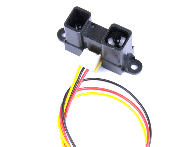
At the same infrared sensor, the reflected signal (a beam in the infrared spectrum) through the lens falls on a position-sensitive photocell, which changes its conductivity depending on the point of reception of the beam.
Perhaps the reader will ask, why would they need two sensors doing the same thing? It all depends on the application of the sensor, so the infrared sensor is poorly suited to measure the distance to light-absorbing or transparent surfaces, since it is based on light. On the other hand, the ultrasonic range finder is poorly suited for determining the distance to sound-absorbing surfaces, in particular, fluffy :) Also, infrared sensors have a smaller range of measured distances (for example, 4-30, 10-80 or 80-150 cm), whereas even the cheapest the range finder determines distances from 2 to 400 cm. In my set there was only an ultrasonic range finder, therefore for experiments I used only it.
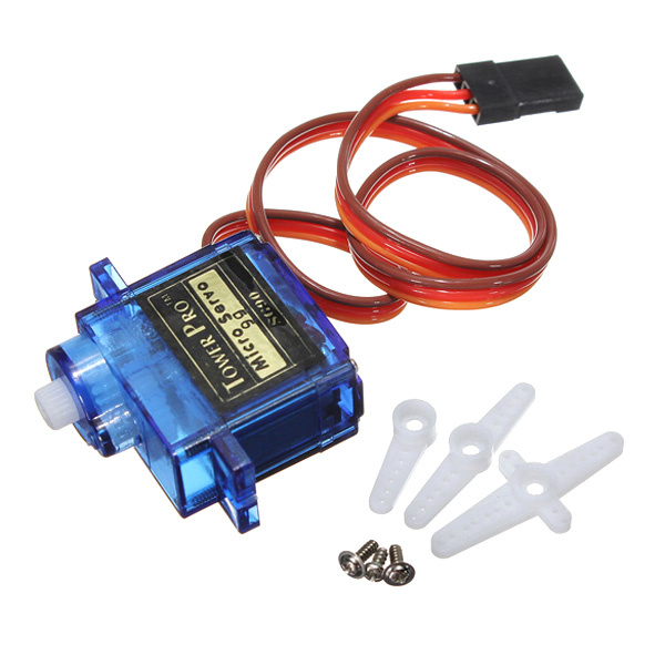
What is a servomotor ? This is a small electric motor, which is combined with a potentiometer and a control circuit. By applying a PWM signal to the servomotor input, we can set the angle by which it should turn and hold this position. Usually the maximum angle of rotation is 180 degrees, but there are servomotors with angles from 120 to 270 degrees.
Having played enough with the servo and ultrasonic rangefinder separately, I began to think about which device to assemble this week. The decision came suddenly when I drove out of the underground parking of the mall. At the exit is organized throughput system with a barrier and a traffic light, which I decided to model.
To build this device, I used the elements of the constructor, preserved from school.


Since the power from the computer was clearly insufficient, the board periodically rebooted, so the powerbank was used in the final version for power.
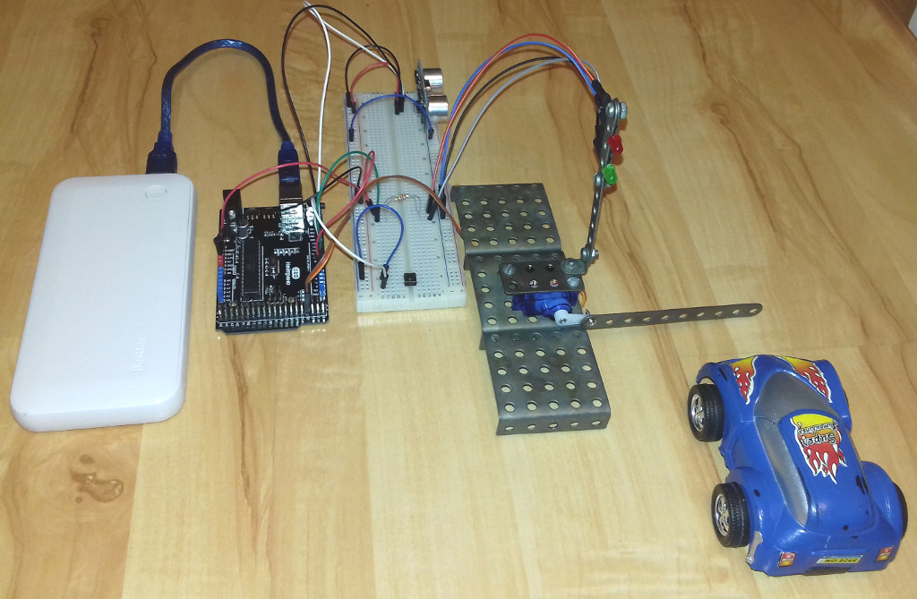
Actually, how our simplified throughput system model works:
- After switching on, the red signal lights up, the barrier is set to the closed position. The system waits for the button to be pressed (imitation of the skip read).
- After pressing the button, the green signal lights and the barrier opens. The system waits for the rangefinder readings to be below a certain value (car travel).
- After the vehicle crosses the rangefinder signal, the red signal lights again and the barrier closes. The system goes back to standby.
In the Fritzing environment, the scheme is as follows:

#include <Servo.h> // #define GATE_PIN 3 #define RED_PIN 4 #define GREEN_PIN 5 #define BUTTON_PIN 6 #define SENSOR_TRIG 11 #define SENSOR_ECHO 12 // #define GREEN 1 #define RED 0 #define CLOSE 1 #define OPEN 0 // , #define GATE_OPEN 180 #define GATE_CLOSE 90 // , #define SENSOR_THR 15 Servo gate; void setup() { Serial.begin(9600); // Serial.println("Initialize gate"); gate.attach(GATE_PIN); gate.write(CLOSE); // Serial.println("Setup pins"); pinMode(GREEN_PIN, OUTPUT); pinMode(RED_PIN, OUTPUT); pinMode(BUTTON_PIN, INPUT_PULLUP); pinMode(SENSOR_TRIG, OUTPUT); pinMode(SENSOR_ECHO, INPUT); Serial.println("Light red"); light(RED); } // - void gateSet(int state) { if (state == CLOSE) { for (int i = GATE_OPEN; i >= GATE_CLOSE; i--) { gate.write(i); delay(15); } } else { for (int i = GATE_CLOSE; i <= GATE_OPEN; i++) { gate.write(i); delay(15); } } } // void light(int col) { if (col == RED) { digitalWrite(GREEN_PIN, LOW); digitalWrite(RED_PIN, HIGH); } else { digitalWrite(GREEN_PIN, HIGH); digitalWrite(RED_PIN, LOW); } } // / int getDistance() { digitalWrite(SENSOR_TRIG, HIGH); digitalWrite(SENSOR_TRIG, LOW); int distance = pulseIn(SENSOR_ECHO, HIGH) / 54; Serial.println("Distance is :" + String(distance)); return distance; } // , bool waitCar() { while (getDistance() > SENSOR_THR) { delay(10); } while (getDistance() <= SENSOR_THR) { delay(10); } } void loop() { Serial.println("Wait button"); while (digitalRead(BUTTON_PIN)) { delay(10); } Serial.println("Light green"); light(GREEN); Serial.println("Open gate"); gateSet(OPEN); Serial.println("Wait for car"); waitCar(); Serial.println("Light red"); light(RED); Serial.println("Close gate"); gateSet(CLOSE); Serial.println("End loop"); } Demonstration of the assembled device
Let's sum up. This week we learned how to work with rangefinders, as well as control the servo drive. These elements are the basis for a variety of wheeled or walking robots, as well as various manipulators, therefore they provide a large space for creativity.
Previous Reviews :
And the link to the course: We build robots and other devices on the Arduino. From traffic light to 3D printer
')
Source: https://habr.com/ru/post/403841/
All Articles