Connect gamepad from PS1 / PS2 to Raspberry pi
May holidays in the yard. So time to eat kebabs and use a variety of draft and bottled beverages. And I do all nonsense. The idea of this project came, even before the new year. But for a long time I could not implement it. Having bought the first gamepad (which I threw out afterwards), and having tried to interrogate it, I realized that there is no longer enough to do by simply reading the manuals, although there is enough information. Fortunately, on this February 23, I received as a gift not shaving foam, packed in socks, but 600 p. With the wish not to deny yourself anything on Aliexpress. Where the Chinese copy of the Saleae Logic logic analyzer was purchased. Those who are interested in what came out of it can click on the button below. And those who are too lazy to read can immediately see the result here .
Having screwed the logic analyzer to a plain construction, I saw that a candid slag was being sent to the gamepad.
Minute theory.
')
The fact is that the console with the gamepad communicate on the SPI interface. And there are regulated modes of operation of this interface. In this case, there should be MODE 3, transmission of the low-order bit forward, and the logic level on the Chip enable line or Select slave when accessing the “0” gamepad. The frequency on the line is clk 250 kHz. But I did 100 kHz, and it works fine. Everything in principle is clearly described here . A system of commands gamepad, and decoding the answers here . Also on the portal "Radiokot", there is a publication, but there are errors in the teams. Simply put, to poll a standard gamepad, you need to give it a command:
Where 0x41 is the type of gamepad, and the last 2 bytes is the state of the buttons. With analog, everything is the same, only you need to add 4 more bytes to the package.
Here 0x73 this means that the gamepad is analog, the last 4 bytes are the state of the analogs.
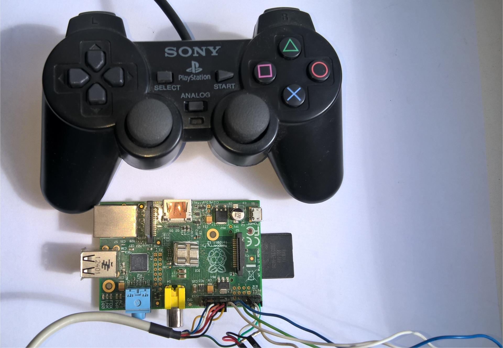
It is important that the gamepad works from 3.3 V., which allows it to be powered directly from the Raspberry pi. In the standard mode (only the buttons work), the consumption is about 2 mA, in the analog mode 12 mA. And then these 10 mA adds a LED on the gamepad. And on the line 3.3 In the Raspberry pi you can put the load up to 50 mA.
Actually, to connect the gamepad, you will need any 4 GPIO ports and power. Only 6 wires.
So here. I realized that the libraries for working with GPIO, that bcm2835, that wiringPi, work very poorly with SPI. In principle, they do not know how to send parcels with the least significant bit forward. In the docks of one of them, this is honestly described, but somewhere very deep. And the regimes they really do not know how to comply.
But nothing prevents to reproduce the parcel itself, and read the data from the gamepad. No sooner said than done. Take the library wiringPi and write:
Everything is classic, we declare GPIO ports, variables and an array of commands. Next, the port operation modes are configured, and the clk, mosi and ce (chip enable) lines are reset to the initial state. Then 2 cycles are formed. In the first, the command bytes are scrolled, and in the second, the bytes themselves are scored bit-wise, in order to apply a logical one or zero to the mosi line, depending on the value of the bit. And at the same time read the answer. When I saw in return the cherished:
I almost jumped to the ceiling. Here is an example of the output of the program, in this case, I was playing with the left analog.
Well, then had to integrate this code into the emulator. In this case, the issue with the choice of the emulator was not. Uniquely pcsx_rearmed . Just as in the previous time, it was necessary to find a function that is one of the first to be launched in order to initialize the library into it. This function turned out to be psxInit, it is located in the r3000a.c file, which emulates the operation of the central processor. This file also added a library header file and announced GPIO ports. In the psxInit function, I initialize the library and set the initial levels on the GPIO ports. Below are the first lines of this file with the changes.
Next, it was necessary to figure out how the emulator imitates the work of the gamepad. There is a header file psemu_plugin_defs.h, it is located in the include directory, here it has a structure that defines the variables in which it is stored - the type of gamepad - standard, analog, the state of the buttons, the variable states of analogs, and the vibration control variables.
So, the main task is to write the data in these variables. This emulator has plugins. Including the gamepad plugin, in the plugins directory there is a dfinput subdirectory in which the pad.c file is located, in which the state of the gamepad is read, as well as its settings. This is where the code from the test program was transferred. Also, the ports, and the library header file are declared. Also in it there are variables that store the code of the commands sent to the gamepad. These variables are used in the functions for accessing the gamepad. Below is this piece of code:
We are interested in the very first one, which has a value of 42. That’s when calling this variable the code will be executed. Especially because in the original file it is empty. And in the brute force function do_cmd, I inserted the main code:
Then, when the current command is reading, the gamepad is polled and data is written to variables, and then the emulator itself takes it.
Well and everything, it was necessary only to compile the project. In order for the compiler to pick up the wirigPi library, you need to insert a link to it in the project's Makefile. It is enough to do at the beginning.
And important. In order to use an analog gamepad, the emulator in the settings you must specify that it is used.
I do not have so many games for PS1, I checked 7 pieces somewhere. It did not work on Tomb Raider2 and Nuclear strike, but this is probably because these games do not know what an analog gamepad is. Probably you need to choose a standard in the settings and try.
PS The emulator itself is best collected with optimization flags. This is well described here .
Having screwed the logic analyzer to a plain construction, I saw that a candid slag was being sent to the gamepad.
Minute theory.
')
The fact is that the console with the gamepad communicate on the SPI interface. And there are regulated modes of operation of this interface. In this case, there should be MODE 3, transmission of the low-order bit forward, and the logic level on the Chip enable line or Select slave when accessing the “0” gamepad. The frequency on the line is clk 250 kHz. But I did 100 kHz, and it works fine. Everything in principle is clearly described here . A system of commands gamepad, and decoding the answers here . Also on the portal "Radiokot", there is a publication, but there are errors in the teams. Simply put, to poll a standard gamepad, you need to give it a command:
0x1 0x42 0x0 0x0 0x0 , - 0xff 0x41 0x5a 0xff 0xff Where 0x41 is the type of gamepad, and the last 2 bytes is the state of the buttons. With analog, everything is the same, only you need to add 4 more bytes to the package.
0x1, 0x42, 0x0, 0x0, 0x0, 0x0, 0x0, 0x0, 0x0 , - 0xff 0x73 0x5a 0xff 0xff 0x80 0x80 0x80 0x80 Here 0x73 this means that the gamepad is analog, the last 4 bytes are the state of the analogs.
It is important that the gamepad works from 3.3 V., which allows it to be powered directly from the Raspberry pi. In the standard mode (only the buttons work), the consumption is about 2 mA, in the analog mode 12 mA. And then these 10 mA adds a LED on the gamepad. And on the line 3.3 In the Raspberry pi you can put the load up to 50 mA.
Actually, to connect the gamepad, you will need any 4 GPIO ports and power. Only 6 wires.
So here. I realized that the libraries for working with GPIO, that bcm2835, that wiringPi, work very poorly with SPI. In principle, they do not know how to send parcels with the least significant bit forward. In the docks of one of them, this is honestly described, but somewhere very deep. And the regimes they really do not know how to comply.
But nothing prevents to reproduce the parcel itself, and read the data from the gamepad. No sooner said than done. Take the library wiringPi and write:
#include <stdio.h> #include <unistd.h> #include <wiringPi.h> #define mosi 12 #define miso 13 #define clk 14 #define ce 5 unsigned char i, b; unsigned char cmd[9] = {0x1, 0x42, 0x0, 0x0, 0x0, 0x0, 0x0, 0x0, 0x0}; int main() { wiringPiSetup () ; // pinMode (mosi, OUTPUT); pinMode (clk, OUTPUT); pinMode (ce, OUTPUT); pinMode (miso, INPUT); digitalWrite (clk, HIGH); digitalWrite (mosi, LOW); digitalWrite (ce, HIGH); while(1) { unsigned char data[9] = {0}; digitalWrite (ce, LOW); delayMicroseconds(20); for (i = 0; i < 9; i++) { for (b = 0; b < 8; b++) { if (((cmd[i] >> b)&1) == 1) { digitalWrite (mosi, HIGH); digitalWrite (clk, LOW); delayMicroseconds(5); digitalWrite (clk, HIGH); data[i] ^= digitalRead(miso) << b; delayMicroseconds(5); digitalWrite (mosi, LOW); } else { digitalWrite (clk, LOW); delayMicroseconds(5); digitalWrite (clk, HIGH); data[i] ^= digitalRead(miso) << b; delayMicroseconds(5); } } delayMicroseconds(40); } digitalWrite (ce, HIGH); printf("%x %x %x %x %x %x\n", data[3], data[4], data[5], data[6], data[7], data[8]); delayMicroseconds(100); } } Everything is classic, we declare GPIO ports, variables and an array of commands. Next, the port operation modes are configured, and the clk, mosi and ce (chip enable) lines are reset to the initial state. Then 2 cycles are formed. In the first, the command bytes are scrolled, and in the second, the bytes themselves are scored bit-wise, in order to apply a logical one or zero to the mosi line, depending on the value of the bit. And at the same time read the answer. When I saw in return the cherished:
0xff 0x41 0x5a 0xff 0xff I almost jumped to the ceiling. Here is an example of the output of the program, in this case, I was playing with the left analog.
ff ff 80 80 ff 80 ff ff 80 80 ff 80 ff ff 80 80 ff 80 ff ff 80 80 ff 80 ff ff 80 80 ff 80 ff ff 80 80 ff 80 ff ff 80 80 ff 40 ff ff 80 80 ff 4b ff ff 80 80 ff 4b ff ff 80 80 ff 4b ff ff 80 80 ff 4b ff ff 80 80 ff 4b ff ff 80 80 ff 1a ff ff 80 80 ff 1a ff ff 80 80 ff 1a ff ff 80 80 ff 1a ff ff 80 80 ff 1a ff ff 80 80 ff 0 Well, then had to integrate this code into the emulator. In this case, the issue with the choice of the emulator was not. Uniquely pcsx_rearmed . Just as in the previous time, it was necessary to find a function that is one of the first to be launched in order to initialize the library into it. This function turned out to be psxInit, it is located in the r3000a.c file, which emulates the operation of the central processor. This file also added a library header file and announced GPIO ports. In the psxInit function, I initialize the library and set the initial levels on the GPIO ports. Below are the first lines of this file with the changes.
#include "r3000a.h" #include "cdrom.h" #include "mdec.h" #include "gte.h" #include <wiringPi.h> #define mosi 12 #define miso 13 #define clk 14 #define ce 5 R3000Acpu *psxCpu = NULL; psxRegisters psxRegs; int psxInit() { SysPrintf(_("Running PCSX Version %s (%s).\n"), PACKAGE_VERSION, __DATE__); wiringPiSetup () ; // pinMode (mosi, OUTPUT); pinMode (clk, OUTPUT); pinMode (ce, OUTPUT); pinMode (miso, INPUT); digitalWrite (clk, HIGH); digitalWrite (mosi, LOW); digitalWrite (ce, HIGH); #ifdef PSXREC if (Config.Cpu == CPU_INTERPRETER) { psxCpu = &psxInt; } else psxCpu = &psxRec; #else psxCpu = &psxInt; #endif Log = 0; if (psxMemInit() == -1) return -1; return psxCpu->Init(); } Next, it was necessary to figure out how the emulator imitates the work of the gamepad. There is a header file psemu_plugin_defs.h, it is located in the include directory, here it has a structure that defines the variables in which it is stored - the type of gamepad - standard, analog, the state of the buttons, the variable states of analogs, and the vibration control variables.
typedef struct { // controler type - fill it withe predefined values above unsigned char controllerType; // status of buttons - every controller fills this field unsigned short buttonStatus; // for analog pad fill those next 4 bytes // values are analog in range 0-255 where 127 is center position unsigned char rightJoyX, rightJoyY, leftJoyX, leftJoyY; // for mouse fill those next 2 bytes // values are in range -128 - 127 unsigned char moveX, moveY; unsigned char Vib[2]; unsigned char VibF[2]; unsigned char reserved[87]; } PadDataS; So, the main task is to write the data in these variables. This emulator has plugins. Including the gamepad plugin, in the plugins directory there is a dfinput subdirectory in which the pad.c file is located, in which the state of the gamepad is read, as well as its settings. This is where the code from the test program was transferred. Also, the ports, and the library header file are declared. Also in it there are variables that store the code of the commands sent to the gamepad. These variables are used in the functions for accessing the gamepad. Below is this piece of code:
#include <stdint.h> #include "../include/psemu_plugin_defs.h" #include "main.h" #include <wiringPi.h> #define mosi 12 #define miso 13 #define clk 14 #define ce 5 unsigned char a, b; unsigned char cmd[9] = {0x1, 0x42, 0x0, 0x0, 0x0, 0x0, 0x0, 0x0, 0x0}; enum { ANALOG_LEFT = 0, ANALOG_RIGHT, ANALOG_TOTAL }; enum { CMD_READ_DATA_AND_VIBRATE = 0x42, CMD_CONFIG_MODE = 0x43, CMD_SET_MODE_AND_LOCK = 0x44, CMD_QUERY_MODEL_AND_MODE = 0x45, CMD_QUERY_ACT = 0x46, // ?? CMD_QUERY_COMB = 0x47, // ?? CMD_QUERY_MODE = 0x4C, // QUERY_MODE ?? CMD_VIBRATION_TOGGLE = 0x4D, }; We are interested in the very first one, which has a value of 42. That’s when calling this variable the code will be executed. Especially because in the original file it is empty. And in the brute force function do_cmd, I inserted the main code:
static uint8_t do_cmd(void) { PadDataS *pad = &padstate[CurPad].pad; int pad_num = CurPad; unsigned char data[9] = {0}; CmdLen = 8; switch (CurCmd) { case CMD_SET_MODE_AND_LOCK: buf = stdmode[pad_num]; return 0xF3; case CMD_QUERY_MODEL_AND_MODE: buf = stdmodel[pad_num]; buf[4] = padstate[pad_num].PadMode; return 0xF3; case CMD_QUERY_ACT: buf = unk46[pad_num]; return 0xF3; case CMD_QUERY_COMB: buf = unk47[pad_num]; return 0xF3; case CMD_QUERY_MODE: buf = unk4c[pad_num]; return 0xF3; case CMD_VIBRATION_TOGGLE: buf = unk4d[pad_num]; return 0xF3; case CMD_CONFIG_MODE: if (padstate[pad_num].ConfigMode) { buf = stdcfg[pad_num]; return 0xF3; } // else FALLTHROUGH case CMD_READ_DATA_AND_VIBRATE: digitalWrite (ce, LOW); delayMicroseconds(20); for (a = 0; a < 9; a++) { for (b = 0; b < 8; b++) { if (((cmd[a] >> b)&1) == 1) { digitalWrite (mosi, HIGH); digitalWrite (clk, LOW); delayMicroseconds(5); digitalWrite (clk, HIGH); data[a] ^= digitalRead(miso) << b; delayMicroseconds(5); digitalWrite (mosi, LOW); } else { digitalWrite (clk, LOW); delayMicroseconds(5); digitalWrite (clk, HIGH); data[a] ^= digitalRead(miso) << b; delayMicroseconds(5); } } delayMicroseconds(40); } digitalWrite (ce, HIGH); pad->buttonStatus = data[4]; pad->buttonStatus = pad->buttonStatus << 8; pad->buttonStatus |= data[3]; pad->rightJoyX = data[5]; pad->rightJoyY = data[6]; pad->leftJoyX = data[7]; pad->leftJoyY = data[8]; default: buf = stdpar[pad_num]; buf[2] = pad->buttonStatus; buf[3] = pad->buttonStatus >> 8; if (padstate[pad_num].PadMode == 1) { buf[4] = pad->rightJoyX; buf[5] = pad->rightJoyY; buf[6] = pad->leftJoyX; buf[7] = pad->leftJoyY; } else { CmdLen = 4; } return padstate[pad_num].PadID; } } Then, when the current command is reading, the gamepad is polled and data is written to variables, and then the emulator itself takes it.
Well and everything, it was necessary only to compile the project. In order for the compiler to pick up the wirigPi library, you need to insert a link to it in the project's Makefile. It is enough to do at the beginning.
# Makefile for PCSX ReARMed # default stuff goes here, so that config can override TARGET ?= pcsx CFLAGS += -Wall -ggdb -Ifrontend -ffast-math -I/usr/include -I/usr/include/SDL LDLIBS += -lpthread -lSDL -lpng -lwiringPi ifndef DEBUG CFLAGS += -DNDEBUG -g endif CXXFLAGS += $(CFLAGS) #DRC_DBG = 1 #PCNT = 1 And important. In order to use an analog gamepad, the emulator in the settings you must specify that it is used.
I do not have so many games for PS1, I checked 7 pieces somewhere. It did not work on Tomb Raider2 and Nuclear strike, but this is probably because these games do not know what an analog gamepad is. Probably you need to choose a standard in the settings and try.
PS The emulator itself is best collected with optimization flags. This is well described here .
Source: https://habr.com/ru/post/403753/
All Articles