Tax preparation in 1950: IBM 403 "programming" with a plug-in panel
Long before the advent of modern computers, business used electromechanical accounting machines (BM) for data processing. These machines, weighing a ton, were “programmed” with wires on a plug-in control panel, which allowed them to create complex business reports based on the data contained on punched cards . And although they did not have electronics and they used rotating mechanical wheels to summarize the data, but these machines could process more than two cards per second.
IBM 403 plug-in dashboard tax deduction
In honor of the April 15th [traditional US tax filing day], I will study the plug-in panel (WB) used to prepare taxes in 1950 and explain the forgotten art of WB programming, showing how wire entanglement can implement a data processing algorithm. Fixing the panel on the BM, the operator could perform a certain task of data processing. Although the panel looks like a spaghetti code physically embodied, connection tracking reveals its function: it calculated tax deductions, summing records from many fields, outputted a report with intermediate and total sums, and punched a smaller set of final cards, recording these sums on them.
Punch cards served as the basis for data processing from the 1890s to the 1970s, and they were used for accounting operations, inventory, payroll and many other tasks. Typically, one 80-column punch card contained one record, and the data was stored in fixed fields of the card. The photo below shows a map with columns divided into fields such as date, vendor number, order number and quantity. BM processed these cards, added numbers and issued a report with subtotals for bills and departments, as shown below.
')

The punch card processing system was invented by Hermann Hollerith for the US census of 1890, in which the simplest tabulator was used , counting the records by the holes in the maps. To summarize, tabs used a module called “battery”, whose round dials contained decimal places. The battery gave the name to the register of processors used to this day. For example, in Intel x86 processors there is a register EAX, that is, EXtended Accumulator. These machines, gradually overgrown with possibilities, became complex BM, capable of issuing business reports. They became popular in the business environment and by 1944 IBM had already provided 10,000 tabs and BMs. In July 1948, IBM introduced the 402 Accounting Machine, on which the WB I was considering was used. The 402nd and 403rd models of machines had rich capabilities: they had 16 counters, many levels for intermediate amounts, control of vertical distances to support forms, they supported comparisons, conditional operators, and removal of leading zeros.
IBM 403 with punch card sorter Type 82
What is surprising in this story is that enterprises were engaged in processing data from punch cards decades before the advent of computers, used purely electromechanical machines, and did not even use electronic tubes. This equipment consisted of components such as a wire brush for reading holes in punch cards, a relay for controlling circuits, and mechanical counting wheels for adding quantities. These technologically primitive systems have revolutionized the processing of enterprise data and paved the way for electronic business computers like the IBM 1401 .
BM were programmed to perform a specific task by placing the wires on the SHP. Since each application used maps with fields in different places, BM required a way to determine the value of each of the fields. Different reports were generated based on values located in different parts of the village. Applications needed to calculate intermediate and total sums of different values. Before the advent of computers capable of storing programs, technology was needed to simply configure the system for a particular application. As a result, a system of placement of wires on SHP.
The photo panel is shown close. It has a grid of holes (nodes) with marked functions. By inserting a wire into the panel, you connect the two nodes, which causes the BM to perform a certain operation. The set of wires determines the operations performed on each of the cards.

When a wire is inserted into the panel, the plug at its end protrudes from the back of the panel, as shown at the top. When the panel is placed on the BM (below), the plugs are in contact with the grid of the BM connectors, closing the necessary circuits (pay attention to the setting switches, which I will discuss below).
Since the WB is removable, companies could easily change the panels to perform different tasks (each time it was necessary to poke wires into the panels for a new function would be too time consuming). As a result, the companies had entire shelves full of panels, tuned to all operations performed. In this form, "software" occupies a tangible physical space. The photo below shows a collection of panels from one of the companies intended for different tasks.

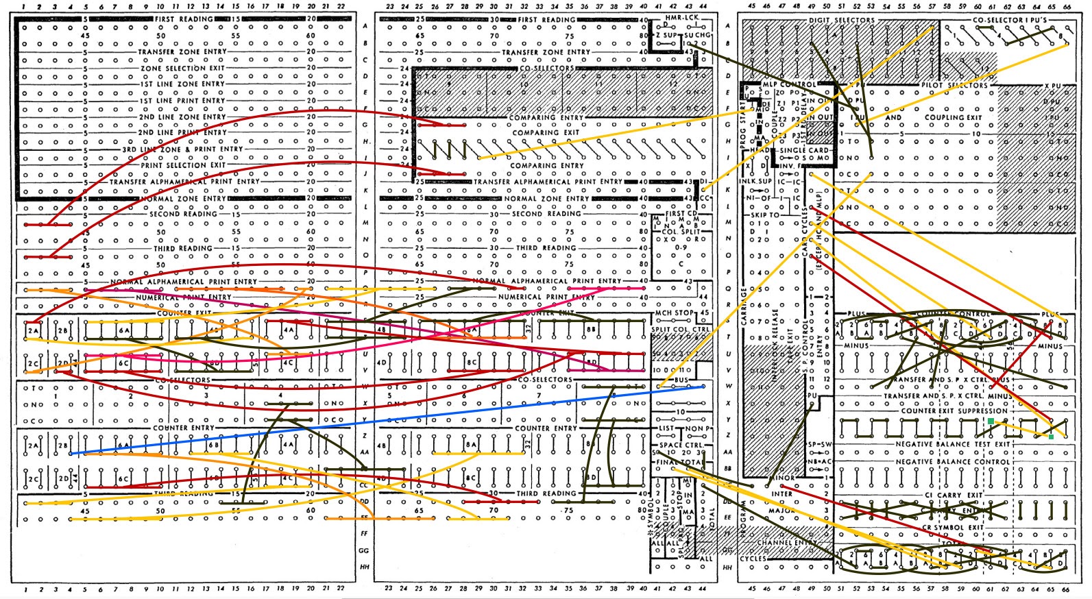
I have carefully studied the location of the wires on the tax bureau to understand what it does. The first step is to track each wire and match it with the wiring diagram (below), where all panel connectors are shown. By comparing the diagram with a photo of the panel at the beginning of the article, you will find that it shows the same wiring, only in a much more readable form.
I found that the program, "recorded" in the wires, reads the cards and counts the intermediate and total amounts of data from the cards. More specifically, each card has seven readable fields. The first is an identifier, and all cards with one identifier are summed up, as a result of which sums are issued for each of the five fields. It seems to me that this id was assigned to an employee, and each card corresponded to one payout period. Or the id could belong to a division of the company, and the map - to the department. Due to the lack of variable names, this cannot be accurately determined.
Summation of records for each id gives the total tax deductions for this employee (from the beginning of the calendar year ). The five summable fields can relate to salary deductions, such as federal income tax, state tax, social security, medicine, and retirement tax. After reading the cards related to the employee, BM punches the new, final card with the total amounts of deductions, and prints the line of the report. Sub-totals for all employees are summed up to get the total.
And this is how SHP works. When reading an 80plot card, each digit is available on one of the reading nodes, numbered from 1 to 80. Connecting the wire to the node allows you to transfer the digit to another part of the machine. Suppose, for example, that columns 28-33 contain a 6-digit number, and we want to add these numbers. This is done by connecting the wire of the 28th reading column to the highest digit of the counter, the 29th column to the next digit, and so on. - only 6 wires.
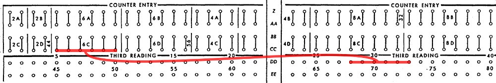
In the photo below you can see six red wires that transmit the field to the 6C counter. The 80 columns of the map read two rows of nodes under the “Third reading” sign. At the entrance to the counters are four rows of nodes under the inscription "Counter entry". The remaining fields in the same way are wired with counters.

From the photo it is difficult to understand the wiring, so usually the wiring diagram of the panel is shown in the diagram. Below it shows the connection of reading columns (on the right) with a 6C counter (on the left). The six wires in the diagram are depicted in one, in the style of the image of charts from IBM. Horizontal stripes connected by a line represent six parallel wires.
To display the total amount, the counter output is connected to the desired printer columns. On the panel, these columns are marked as “print entry”: 43 "alphanumeric printed positions", capable of printing letters or numbers, followed by 45 digital positions, capable of printing only numbers. The diagram below shows the four wires from the 4C counter, leading to the printing positions from 1 to 4 (yellow), and six wires from the 6C counter (red) to the printed columns 35-40.

BM contains 16 decimal counters. 4 of them - 8-bit, they are called 8A, 8B, 8C and 8D. Four 6-bit (6A - 6D), four 4-bit (4A - 4D), and four - 2-bit (2A - 2D). In addition, two counters can be combined, and get a larger counter. There are also links between counters for calculating subtotals. For example, counter 8A collects an interim total for employees. These totals are added to counter 8B, and form a grand total.
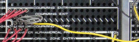
Another important operation is comparing the id of two cards. If they have the same id, they need to be counted together, and if they are different, they need to display the subtotal and reset the counters. Comparison is performed by writing two fields in two rows to compare the “comparing entry” entries. If they are different, the signal goes to the “comparing exit” output. Since we want to compare the current map with the next one, we take one field from the “second reading” and one from the “third reading”. The map processed by us will be at the stage of the third reading, and the card after it will be at the stage of the second reading. Finally, the comparison output is wired to the “program start (minor)” node. As a result, the BM starts an additional cycle with printing out the subtotals of the junior level “minor” and resets the counters. BM has two additional levels of subtotals, “intermediate” and “major” (middle and senior).

Columns 1-4 of cards are compared to find out if you need to print subtotals
In the diagram above, columns 1–4 from the second and third readings are connected to the nodes of the comparison records. The four corresponding output nodes are wired (gray) and connected to the lowest (MI) program start node (the yellow wire to the PRG START is in the upper right). The enlarged photo below shows the location of the wires.
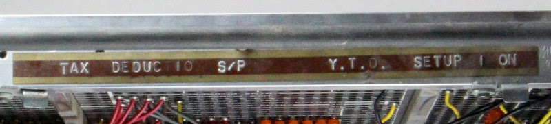
Another interesting feature of NB is conditional behavior using switches. Connections can be switched depending on the signal, which allows the machine to change its behavior depending on the comparison results or on the state of the switches on the panel. This Silo changes the behavior based on the “setup change 1” switch, one of the switches on the BM at the top of the panel. You can imagine this as a prototype of the command line settings. According to the label on the NB, the switch turns on the mode “from the beginning of the calendar year”. It includes processing of one field, and also switches between constants 2 and 5 added to the counter 2B (the purpose of these constants remains a mystery to me).
The wires from the right side of the silo process control the behavior of the meter - for example, the accumulation of intermediate or total totals. They also connect several counters together for their consolidation. For example, counters 2C and 4D are combined to work as a single 6-digit counter.
The table shows the WB wiring diagram showing the relationship between input fields and printer output.
Columns 14-17 are cumulative, but not printed. Perhaps their values are punched on the final punch card. Columns 34-38 are processed only when the “setup change 1” toggle is on. The counter 2B is controlled by a toggle switch on the panel, at each step 2 or 5 is added to it.
Another interesting feature of the machine is the perforation of the totals. It allows you to process a large stack of punched cards and issue a small file with amounts. The WB for taxes is set up so that for each employee one summarizing punch card is punched. Thus, a set of employee cards with data for each payment period is reduced to one card with annual amounts. This card can already be used in further processing.
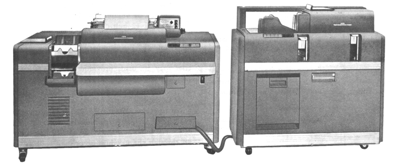
IBM 403 bukhmashina connected to a punching device of the 519th model
Perforation of the results is carried out by attaching a punching machine to the BM with a thick cable. A wire inserted into one of the NB units controls the activation of the perforation, and in the other - the moment at which it is needed. The SPP with taxes is set up so that the final card is broken through for each subtotal. A separate SP on a punching machine controls which columns to punch on the card.
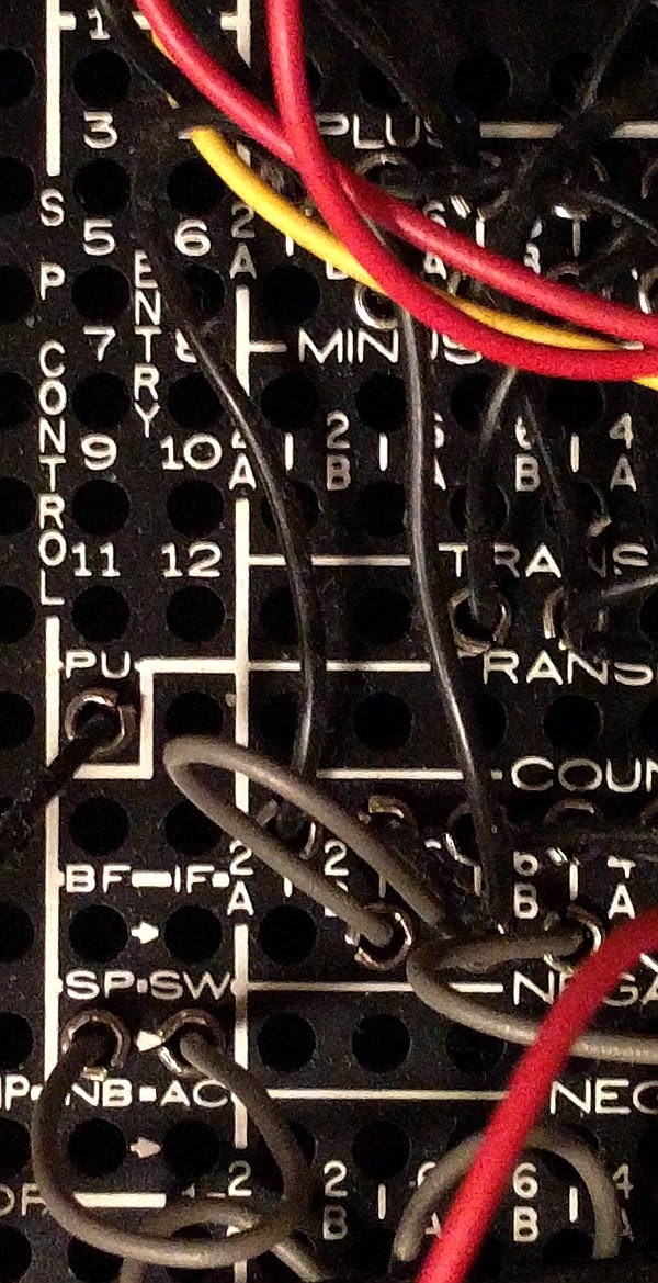
Wires that control the perforation of the final card. Total perforation switch nodes (SP.SW) are connected with gray wire (bottom left)
It is amazing what kind of functionality these BMs could provide without electronic components, using only clever electromechanics. Inside the car contains a maze of motors, rotating shafts, cams and grippers. It looks more like a car than a computer - it even has an oil pump! And with all these mechanical parts, BM weighs more than a ton (1,143 kg).

On the Silk wire, a certain column is transmitted to the card. But how is the symbol from the card transmitted over the wire? How does the counter perform addition? How is the result displayed? BMs use ingenious mechanisms, which are closely related to the structure of punch cards.
Speaking in modern language, the symbol is encoded sequentially - there is a pulse along the wire, the duration of which is connected with the location of the hole on the map. Pulses start and stop the counters. They also control the printheads that display the result.
The 403rd works with time based on the rotation of the shafts and not on the clock. Each turn of the shaft corresponds to the cycle of the card - reading and processing. The fundamental unit of time is a rotation of 18 °: this is between the reading of consecutive card holes, the movement of the print head by one character and the rotation of the counter by one. With a processing speed of 150 cards per minute, it turns out about 400 ms per card and 20 ms per 18 ° rotation — surprisingly quickly for the mechanism.
To understand how BM works, you need to understand how data is stored on punch cards. The punch card stores 80 characters, each of which is represented by a set of holes in a column. The photo shows a map showing the storage of numbers and letters of the alphabet. Each character is printed on top of the map, and the corresponding holes are punched in the column below. The number is just a hole in the desired row, from 0 to 9 (note that the numbers are not stored in binary, but in decimal form). To support the letters above the digital series, two auxiliary, "zonal" are introduced. The letter A is indicated by two holes in the column - zonal and digital.
The zonal row above the zero is called the 11th, or X, and the row above it is the 12th. For some letters, row 0 is used as a zone, and not as digital. Some difficulties are connected with this, for example, the need for a special mechanism that prints "digital zero" instead of "zonal". Such coding for punched cards later turned into EBCDIC (Extended Binary Coded Decimal Interchange Code, Extended Binary Coded Decimal Interchange Code), used on IBM computers instead of ASCII. Many artifacts of this code, in particular, a violation of the alphabetical order, originate in punch cards.

You might think that BM reads cards one column at a time, and processes one character at a time. But the cards are actually read sideways, starting from the bottom. All 80 columns are read in parallel, starting with the 9th row and ending with the zero, and then zonal rows. For reading maps, BM uses a set of 80 wire brushes, one for each column. In the presence of a hole in the brush contact with the metal shaft under the card, it closes the circuit and creates a pulse. Each column will have a pulse corresponding to the aperture, with the 9th row first, then the 8th row, and so on, ending with 0. Therefore, each character is encoded sequentially, and each wire from Silo sends one of these signals, but all columns are processed parallel.
Print

Print heads of the 402nd machine
The mechanism of printing BM consists of 88 print heads. Each head has all the characters that can be printed. The head moves vertically, stopping on the desired symbol, and then the hammer hits it, and the symbol is printed through the ink film. Therefore, all characters in a line of text are printed in parallel.
Wires with SHP determine what to print, stopping each of the heads at the right time so that the correct character is selected. The movement of the heads is precisely synchronized with the reading of the card, so that, say, the 3rd row of the card is read at the same time as the “3” on the print head moves to the print position. If the brush assembly is connected to the printed column assembly, the pulse energizes the magnet, releasing the locking mechanism that clings to the teeth of the print head and stops it so that the “3” symbol is printed. In case “2” is read from the card, the brush will be opposite the hole one unit of time later, the print head will rise one more position, and “2” will be printed.
The printing mechanism consists of a complex articulation of mechanical parts: cams, dogs, guides, springs and clamps, as well as electromagnets that activate these parts at the right time. The mechanism is able to print 100 lines per minute, so parts quickly scurry back and forth and they need to be synchronized exactly. The printheads are shifted by one position every 18 ° of the shaft rotation, and thus synchronized with the reading of the card.
The basis of BM - electromechanical counters, summing values. Each digit is a separate wheel rotated for summation. The location of the wheel corresponds to the value of this discharge. For example, to add to counter 27, the wheel for dozens is rotated by two positions, and the wheel for units is by seven. Therefore, to add the value from the card, the wheels must turn to the appropriate number of revolutions. The wheel rotates when it encounters a hole, rotates one position for each additional row, and stops reading at row 0. Since the 9th row is read first, and the 0th row is the last, the counter is rotated by the number of positions indicated by the position of the hole.

Electromechanical counter of the 403rd car
Above shows a counter of two-digit numbers. The wheels are on the left. The start and stop coils cause the wheels to start and stop at the right time, activating the levers that control the stops. The transfer is carried out with the help of cams under the wheels, closing the contacts. Behind the panel there are electrical contacts that read the value stored on the meter - they are connected to the contact on the right.
NB determines which columns from the card are added to which counters. To add a field value to the counter, the reader's brush is connected to the counter via the WB, so the card controls the rotation of the counter wheels. The signal turns on the meter start-up coil, the stopper releases the wheel and it starts to rotate. At position 0, the locking coil releases the stopper, and it stops the wheel. For example, if the brush read the value “7” from the card, the counter will go through 7 positions and then stop. If the brush reads "1", the counter will turn only one position. Everything works by synchronizing the movement of the map and the rotation of the counter. Rotate 18 ° corresponds to the movement of the card one row and turning the counter one position. The meter has 20 positions, separated by 18 °. Adding 10 turns him half a turn. Subtraction is performed through addition by the method of addition to the nines (subtraction of the number n is replaced by the addition to it 9-n, after which the correction unit is added). To do this, the counter starts from position “9” and stops when the hole is read. For example, if the hole is made at position 7, the counter will turn to 2 positions.
The transfer from one rank to another is performed by a complex mechanism. You might expect that when one wheel goes from 9 to 0, it turns the wheel of the next discharge, as on odometers, but for multivalued counters it would be too slow. The counter adds 150 numbers per minute and turns very quickly. Instead, counters use a scheme similar to an accelerated carry with preview (carry lookahead). If the wheel is at position 9, it closes the contact, and the unit from the bottom of the discharge goes to the top. When the wheel goes from 9 to 0, another contact closes, creating a digit that is kept “in mind”. After all additions, all the numbers “in mind” are created in parallel and are added at one time. Therefore, the addition like 99999999 + 1 does not linger due to chain transfer - they all turn at the same time.
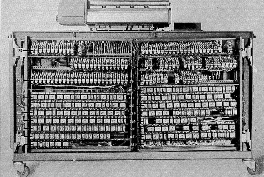
BM is controlled by hundreds of relays, electromechanical switches, heads of the "control logic" of the system. The photo shows the back of the BM, filled with a relay. More relays can be found on the extreme panel. To create timing signals, the switches open and close with cams on a rotating shaft. Therefore, the entire system is synchronized with the rotating shaft.
Punch card processing is now almost forgotten, but it has managed data processing for almost a hundred years. Even before the existence of computers, business enterprises used punch cards and tabs for accounting. IBM accounting machines were able to perform surprisingly complex tasks, even though they consisted of seemingly primitive components. BM and programming PCs were popular until the 1960s, when enterprises began to gradually switch to business computers with program storage, such as IBM 1401. Nevertheless, IBM continued to actively promote BM until 1976. Interestingly, one company in Texas still uses the IBM 402 BM , which demonstrates the amazing durability of punch card technology.
Instructions for different BMs can be downloaded on the Bitsavers website:
• IBM 402, 403 and 419 Accounting Machines: Manual of Operation
• IBM 402, 403, 419 Field Engineering Manual of Instruction
• IBM Functional Wiring Principles
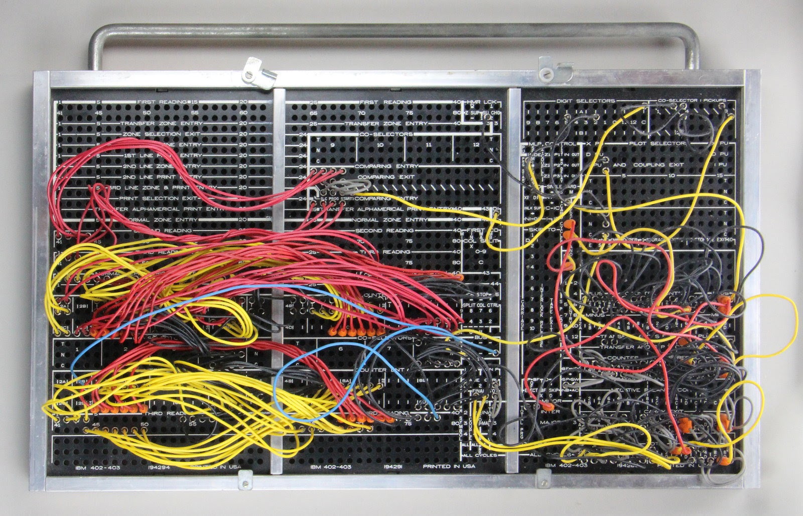
IBM 403 plug-in dashboard tax deduction
In honor of the April 15th [traditional US tax filing day], I will study the plug-in panel (WB) used to prepare taxes in 1950 and explain the forgotten art of WB programming, showing how wire entanglement can implement a data processing algorithm. Fixing the panel on the BM, the operator could perform a certain task of data processing. Although the panel looks like a spaghetti code physically embodied, connection tracking reveals its function: it calculated tax deductions, summing records from many fields, outputted a report with intermediate and total sums, and punched a smaller set of final cards, recording these sums on them.
Punch Card Review
Punch cards served as the basis for data processing from the 1890s to the 1970s, and they were used for accounting operations, inventory, payroll and many other tasks. Typically, one 80-column punch card contained one record, and the data was stored in fixed fields of the card. The photo below shows a map with columns divided into fields such as date, vendor number, order number and quantity. BM processed these cards, added numbers and issued a report with subtotals for bills and departments, as shown below.
')
The punch card processing system was invented by Hermann Hollerith for the US census of 1890, in which the simplest tabulator was used , counting the records by the holes in the maps. To summarize, tabs used a module called “battery”, whose round dials contained decimal places. The battery gave the name to the register of processors used to this day. For example, in Intel x86 processors there is a register EAX, that is, EXtended Accumulator. These machines, gradually overgrown with possibilities, became complex BM, capable of issuing business reports. They became popular in the business environment and by 1944 IBM had already provided 10,000 tabs and BMs. In July 1948, IBM introduced the 402 Accounting Machine, on which the WB I was considering was used. The 402nd and 403rd models of machines had rich capabilities: they had 16 counters, many levels for intermediate amounts, control of vertical distances to support forms, they supported comparisons, conditional operators, and removal of leading zeros.
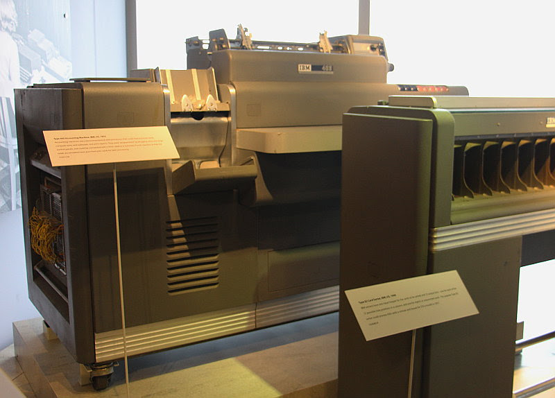
IBM 403 with punch card sorter Type 82
What is surprising in this story is that enterprises were engaged in processing data from punch cards decades before the advent of computers, used purely electromechanical machines, and did not even use electronic tubes. This equipment consisted of components such as a wire brush for reading holes in punch cards, a relay for controlling circuits, and mechanical counting wheels for adding quantities. These technologically primitive systems have revolutionized the processing of enterprise data and paved the way for electronic business computers like the IBM 1401 .
Plug programming
BM were programmed to perform a specific task by placing the wires on the SHP. Since each application used maps with fields in different places, BM required a way to determine the value of each of the fields. Different reports were generated based on values located in different parts of the village. Applications needed to calculate intermediate and total sums of different values. Before the advent of computers capable of storing programs, technology was needed to simply configure the system for a particular application. As a result, a system of placement of wires on SHP.
The photo panel is shown close. It has a grid of holes (nodes) with marked functions. By inserting a wire into the panel, you connect the two nodes, which causes the BM to perform a certain operation. The set of wires determines the operations performed on each of the cards.
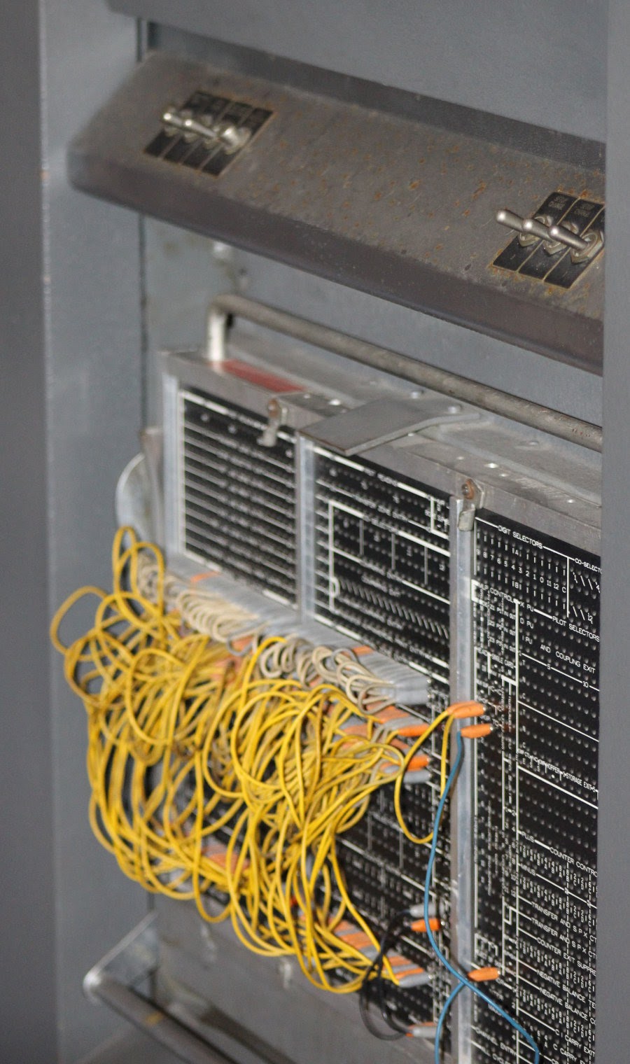
When a wire is inserted into the panel, the plug at its end protrudes from the back of the panel, as shown at the top. When the panel is placed on the BM (below), the plugs are in contact with the grid of the BM connectors, closing the necessary circuits (pay attention to the setting switches, which I will discuss below).
Since the WB is removable, companies could easily change the panels to perform different tasks (each time it was necessary to poke wires into the panels for a new function would be too time consuming). As a result, the companies had entire shelves full of panels, tuned to all operations performed. In this form, "software" occupies a tangible physical space. The photo below shows a collection of panels from one of the companies intended for different tasks.
Tax program
I have carefully studied the location of the wires on the tax bureau to understand what it does. The first step is to track each wire and match it with the wiring diagram (below), where all panel connectors are shown. By comparing the diagram with a photo of the panel at the beginning of the article, you will find that it shows the same wiring, only in a much more readable form.
I found that the program, "recorded" in the wires, reads the cards and counts the intermediate and total amounts of data from the cards. More specifically, each card has seven readable fields. The first is an identifier, and all cards with one identifier are summed up, as a result of which sums are issued for each of the five fields. It seems to me that this id was assigned to an employee, and each card corresponded to one payout period. Or the id could belong to a division of the company, and the map - to the department. Due to the lack of variable names, this cannot be accurately determined.
Summation of records for each id gives the total tax deductions for this employee (from the beginning of the calendar year ). The five summable fields can relate to salary deductions, such as federal income tax, state tax, social security, medicine, and retirement tax. After reading the cards related to the employee, BM punches the new, final card with the total amounts of deductions, and prints the line of the report. Sub-totals for all employees are summed up to get the total.
And this is how SHP works. When reading an 80plot card, each digit is available on one of the reading nodes, numbered from 1 to 80. Connecting the wire to the node allows you to transfer the digit to another part of the machine. Suppose, for example, that columns 28-33 contain a 6-digit number, and we want to add these numbers. This is done by connecting the wire of the 28th reading column to the highest digit of the counter, the 29th column to the next digit, and so on. - only 6 wires.
In the photo below you can see six red wires that transmit the field to the 6C counter. The 80 columns of the map read two rows of nodes under the “Third reading” sign. At the entrance to the counters are four rows of nodes under the inscription "Counter entry". The remaining fields in the same way are wired with counters.
From the photo it is difficult to understand the wiring, so usually the wiring diagram of the panel is shown in the diagram. Below it shows the connection of reading columns (on the right) with a 6C counter (on the left). The six wires in the diagram are depicted in one, in the style of the image of charts from IBM. Horizontal stripes connected by a line represent six parallel wires.
To display the total amount, the counter output is connected to the desired printer columns. On the panel, these columns are marked as “print entry”: 43 "alphanumeric printed positions", capable of printing letters or numbers, followed by 45 digital positions, capable of printing only numbers. The diagram below shows the four wires from the 4C counter, leading to the printing positions from 1 to 4 (yellow), and six wires from the 6C counter (red) to the printed columns 35-40.
BM contains 16 decimal counters. 4 of them - 8-bit, they are called 8A, 8B, 8C and 8D. Four 6-bit (6A - 6D), four 4-bit (4A - 4D), and four - 2-bit (2A - 2D). In addition, two counters can be combined, and get a larger counter. There are also links between counters for calculating subtotals. For example, counter 8A collects an interim total for employees. These totals are added to counter 8B, and form a grand total.
Another important operation is comparing the id of two cards. If they have the same id, they need to be counted together, and if they are different, they need to display the subtotal and reset the counters. Comparison is performed by writing two fields in two rows to compare the “comparing entry” entries. If they are different, the signal goes to the “comparing exit” output. Since we want to compare the current map with the next one, we take one field from the “second reading” and one from the “third reading”. The map processed by us will be at the stage of the third reading, and the card after it will be at the stage of the second reading. Finally, the comparison output is wired to the “program start (minor)” node. As a result, the BM starts an additional cycle with printing out the subtotals of the junior level “minor” and resets the counters. BM has two additional levels of subtotals, “intermediate” and “major” (middle and senior).
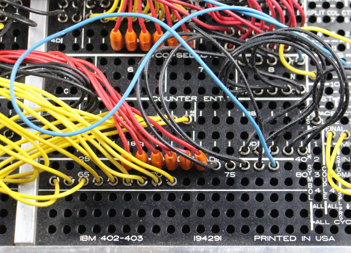
Columns 1-4 of cards are compared to find out if you need to print subtotals
In the diagram above, columns 1–4 from the second and third readings are connected to the nodes of the comparison records. The four corresponding output nodes are wired (gray) and connected to the lowest (MI) program start node (the yellow wire to the PRG START is in the upper right). The enlarged photo below shows the location of the wires.
Another interesting feature of NB is conditional behavior using switches. Connections can be switched depending on the signal, which allows the machine to change its behavior depending on the comparison results or on the state of the switches on the panel. This Silo changes the behavior based on the “setup change 1” switch, one of the switches on the BM at the top of the panel. You can imagine this as a prototype of the command line settings. According to the label on the NB, the switch turns on the mode “from the beginning of the calendar year”. It includes processing of one field, and also switches between constants 2 and 5 added to the counter 2B (the purpose of these constants remains a mystery to me).
The wires from the right side of the silo process control the behavior of the meter - for example, the accumulation of intermediate or total totals. They also connect several counters together for their consolidation. For example, counters 2C and 4D are combined to work as a single 6-digit counter.
The table shows the WB wiring diagram showing the relationship between input fields and printer output.
| Column Cards | Output columns | Intermediate Counter | Total counter |
|---|---|---|---|
| 1-4 | 1-4 | 4C | |
| 34-38 | 5-10 | 8D | 4A / 2D |
| 44-45 | 11-18 | 8A | 8B |
| 61-66 | 19-26 | 6A | 2C / 4D |
| 67-71 | 27-32 | 6B | 2A / 4B |
| 28-33 | 35-40 | 6C | 8C |
| 14-17 | 4D | ||
| With toggle switch | 2b |
Columns 14-17 are cumulative, but not printed. Perhaps their values are punched on the final punch card. Columns 34-38 are processed only when the “setup change 1” toggle is on. The counter 2B is controlled by a toggle switch on the panel, at each step 2 or 5 is added to it.
Another interesting feature of the machine is the perforation of the totals. It allows you to process a large stack of punched cards and issue a small file with amounts. The WB for taxes is set up so that for each employee one summarizing punch card is punched. Thus, a set of employee cards with data for each payment period is reduced to one card with annual amounts. This card can already be used in further processing.
IBM 403 bukhmashina connected to a punching device of the 519th model
Perforation of the results is carried out by attaching a punching machine to the BM with a thick cable. A wire inserted into one of the NB units controls the activation of the perforation, and in the other - the moment at which it is needed. The SPP with taxes is set up so that the final card is broken through for each subtotal. A separate SP on a punching machine controls which columns to punch on the card.
Wires that control the perforation of the final card. Total perforation switch nodes (SP.SW) are connected with gray wire (bottom left)
The insides of the accounting machine №403
It is amazing what kind of functionality these BMs could provide without electronic components, using only clever electromechanics. Inside the car contains a maze of motors, rotating shafts, cams and grippers. It looks more like a car than a computer - it even has an oil pump! And with all these mechanical parts, BM weighs more than a ton (1,143 kg).
On the Silk wire, a certain column is transmitted to the card. But how is the symbol from the card transmitted over the wire? How does the counter perform addition? How is the result displayed? BMs use ingenious mechanisms, which are closely related to the structure of punch cards.
Speaking in modern language, the symbol is encoded sequentially - there is a pulse along the wire, the duration of which is connected with the location of the hole on the map. Pulses start and stop the counters. They also control the printheads that display the result.
The 403rd works with time based on the rotation of the shafts and not on the clock. Each turn of the shaft corresponds to the cycle of the card - reading and processing. The fundamental unit of time is a rotation of 18 °: this is between the reading of consecutive card holes, the movement of the print head by one character and the rotation of the counter by one. With a processing speed of 150 cards per minute, it turns out about 400 ms per card and 20 ms per 18 ° rotation — surprisingly quickly for the mechanism.
Reading cards
To understand how BM works, you need to understand how data is stored on punch cards. The punch card stores 80 characters, each of which is represented by a set of holes in a column. The photo shows a map showing the storage of numbers and letters of the alphabet. Each character is printed on top of the map, and the corresponding holes are punched in the column below. The number is just a hole in the desired row, from 0 to 9 (note that the numbers are not stored in binary, but in decimal form). To support the letters above the digital series, two auxiliary, "zonal" are introduced. The letter A is indicated by two holes in the column - zonal and digital.
The zonal row above the zero is called the 11th, or X, and the row above it is the 12th. For some letters, row 0 is used as a zone, and not as digital. Some difficulties are connected with this, for example, the need for a special mechanism that prints "digital zero" instead of "zonal". Such coding for punched cards later turned into EBCDIC (Extended Binary Coded Decimal Interchange Code, Extended Binary Coded Decimal Interchange Code), used on IBM computers instead of ASCII. Many artifacts of this code, in particular, a violation of the alphabetical order, originate in punch cards.
You might think that BM reads cards one column at a time, and processes one character at a time. But the cards are actually read sideways, starting from the bottom. All 80 columns are read in parallel, starting with the 9th row and ending with the zero, and then zonal rows. For reading maps, BM uses a set of 80 wire brushes, one for each column. In the presence of a hole in the brush contact with the metal shaft under the card, it closes the circuit and creates a pulse. Each column will have a pulse corresponding to the aperture, with the 9th row first, then the 8th row, and so on, ending with 0. Therefore, each character is encoded sequentially, and each wire from Silo sends one of these signals, but all columns are processed parallel.
Print heads of the 402nd machine
The mechanism of printing BM consists of 88 print heads. Each head has all the characters that can be printed. The head moves vertically, stopping on the desired symbol, and then the hammer hits it, and the symbol is printed through the ink film. Therefore, all characters in a line of text are printed in parallel.
Wires with SHP determine what to print, stopping each of the heads at the right time so that the correct character is selected. The movement of the heads is precisely synchronized with the reading of the card, so that, say, the 3rd row of the card is read at the same time as the “3” on the print head moves to the print position. If the brush assembly is connected to the printed column assembly, the pulse energizes the magnet, releasing the locking mechanism that clings to the teeth of the print head and stops it so that the “3” symbol is printed. In case “2” is read from the card, the brush will be opposite the hole one unit of time later, the print head will rise one more position, and “2” will be printed.
The printing mechanism consists of a complex articulation of mechanical parts: cams, dogs, guides, springs and clamps, as well as electromagnets that activate these parts at the right time. The mechanism is able to print 100 lines per minute, so parts quickly scurry back and forth and they need to be synchronized exactly. The printheads are shifted by one position every 18 ° of the shaft rotation, and thus synchronized with the reading of the card.
Counters
The basis of BM - electromechanical counters, summing values. Each digit is a separate wheel rotated for summation. The location of the wheel corresponds to the value of this discharge. For example, to add to counter 27, the wheel for dozens is rotated by two positions, and the wheel for units is by seven. Therefore, to add the value from the card, the wheels must turn to the appropriate number of revolutions. The wheel rotates when it encounters a hole, rotates one position for each additional row, and stops reading at row 0. Since the 9th row is read first, and the 0th row is the last, the counter is rotated by the number of positions indicated by the position of the hole.
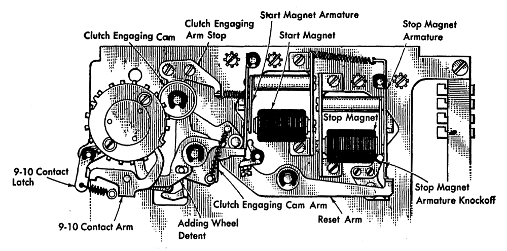
Electromechanical counter of the 403rd car
Above shows a counter of two-digit numbers. The wheels are on the left. The start and stop coils cause the wheels to start and stop at the right time, activating the levers that control the stops. The transfer is carried out with the help of cams under the wheels, closing the contacts. Behind the panel there are electrical contacts that read the value stored on the meter - they are connected to the contact on the right.
NB determines which columns from the card are added to which counters. To add a field value to the counter, the reader's brush is connected to the counter via the WB, so the card controls the rotation of the counter wheels. The signal turns on the meter start-up coil, the stopper releases the wheel and it starts to rotate. At position 0, the locking coil releases the stopper, and it stops the wheel. For example, if the brush read the value “7” from the card, the counter will go through 7 positions and then stop. If the brush reads "1", the counter will turn only one position. Everything works by synchronizing the movement of the map and the rotation of the counter. Rotate 18 ° corresponds to the movement of the card one row and turning the counter one position. The meter has 20 positions, separated by 18 °. Adding 10 turns him half a turn. Subtraction is performed through addition by the method of addition to the nines (subtraction of the number n is replaced by the addition to it 9-n, after which the correction unit is added). To do this, the counter starts from position “9” and stops when the hole is read. For example, if the hole is made at position 7, the counter will turn to 2 positions.
The transfer from one rank to another is performed by a complex mechanism. You might expect that when one wheel goes from 9 to 0, it turns the wheel of the next discharge, as on odometers, but for multivalued counters it would be too slow. The counter adds 150 numbers per minute and turns very quickly. Instead, counters use a scheme similar to an accelerated carry with preview (carry lookahead). If the wheel is at position 9, it closes the contact, and the unit from the bottom of the discharge goes to the top. When the wheel goes from 9 to 0, another contact closes, creating a digit that is kept “in mind”. After all additions, all the numbers “in mind” are created in parallel and are added at one time. Therefore, the addition like 99999999 + 1 does not linger due to chain transfer - they all turn at the same time.
Relay
BM is controlled by hundreds of relays, electromechanical switches, heads of the "control logic" of the system. The photo shows the back of the BM, filled with a relay. More relays can be found on the extreme panel. To create timing signals, the switches open and close with cams on a rotating shaft. Therefore, the entire system is synchronized with the rotating shaft.
Conclusion
Punch card processing is now almost forgotten, but it has managed data processing for almost a hundred years. Even before the existence of computers, business enterprises used punch cards and tabs for accounting. IBM accounting machines were able to perform surprisingly complex tasks, even though they consisted of seemingly primitive components. BM and programming PCs were popular until the 1960s, when enterprises began to gradually switch to business computers with program storage, such as IBM 1401. Nevertheless, IBM continued to actively promote BM until 1976. Interestingly, one company in Texas still uses the IBM 402 BM , which demonstrates the amazing durability of punch card technology.
Instructions for different BMs can be downloaded on the Bitsavers website:
• IBM 402, 403 and 419 Accounting Machines: Manual of Operation
• IBM 402, 403, 419 Field Engineering Manual of Instruction
• IBM Functional Wiring Principles
Source: https://habr.com/ru/post/403749/
All Articles