ITER: switching equipment
As one person aptly put it, “In the ITER project, if there is a stool in the hall, then her seat is necessarily from hafnium with internal cooling channels, and the legs are made of tantalum alloy, and one is brought from Japan, and three others are from the USA.” This project is as if created so that any equipment would be record and astounding.
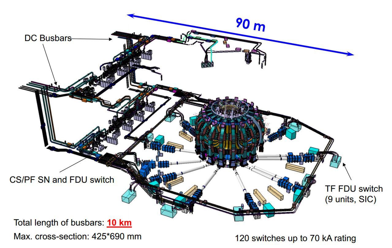
Electrical wiring of the ITER magnets power supply system, including switching equipment.
Today there is a small story about systems that will quickly connect and disconnect ITER superconducting coils and another engineering complexity, especially since in March they passed qualification tests of devices that perform this task.
')
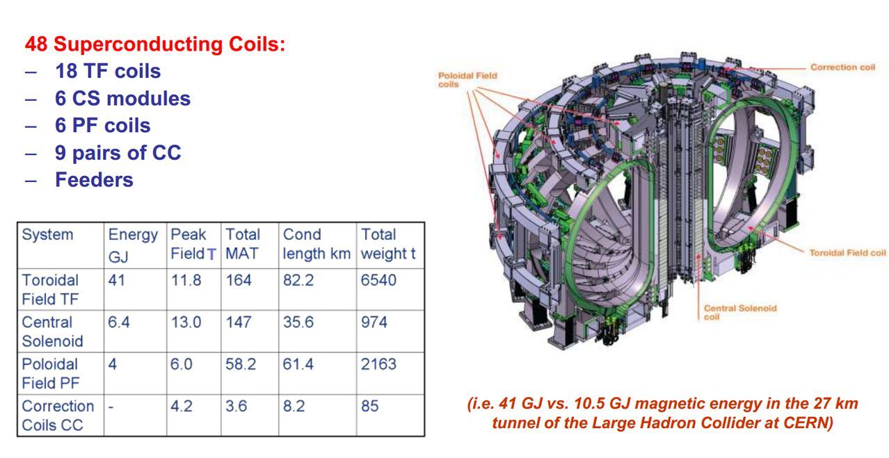
For a start - a little about the electric system of the ITER magnetic system. The international tokamak will have 48 superconducting magnets, namely:
ITER magnetic system diagram
As you can guess, an independent connection is needed to create a different current (= magnetic field strength) in different coils in order to control the plasma (its position, shape, current, etc.). Current control is carried out in two ways: firstly by a set of powerful rectifiers (tens of megawatts, in the total of the order of 250), which smoothly create and change the current in the coils, and secondly by inserting a short resistor (of course, mega-resistors with a total capacity of 2.5 gigawatts (! ), this is ITER) into the coil circuit, in order to remove some of the energy from it.
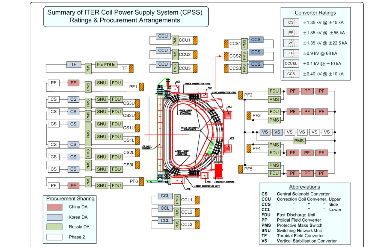
Slightly more detailed scheme of connecting ITER magnets to power sources.
Resistor insertion operations are a classic way to start a tokamak. In this case, a sharp change in the field in the poloidal coils and the central solenoid creates a vortex electric field that breaks through the plasma and induces an annular current in it, which is part of the plasma confinement system.
One ITER resistor assembly module - 2-megawatt steel with air cooling
Today’s hero, SNU (Switching Network Unit), who was tested at NIIEFA in March 2017 (well, and who is more interested, more about the ITER magnet power supply system ) is responsible for introducing resistors into the coil circuits. In total, 8 SNUs will be installed in ITER (on CS and PF1 and PF6 coils).
The main difficulty in creating SNUs is currents up to 60 kiloamperes and a large inductance of switched coils, which leads to the appearance of a voltage of 8.5 kilovolts at the moment of breaking the contacts. Considering the still extremely low resistance of the circuits, the arc in the switch turns out to be ignited with a current of 60 kA, which instantly puts it into an unsuitable state. And we need a switch resource of 30 thousand shutdowns.
Dead end? No, we can do everything much more difficult!

This is the SNU scheme. Unfortunately, we have to understand numerous abbreviations, but we will try: So, SNR are the same resistors that are inserted into the coil circuit, first they are parallel to the circuit through which current flows from the rectifier to the coil formed by the FOS and FDS breakers. At the bottom there is a thyristor counterpulse module TCB, made of two identical circuits TH1, TH2, and in parallel with FOS and FDS - FMS contactors and EPMS emergency pyroseal switch.

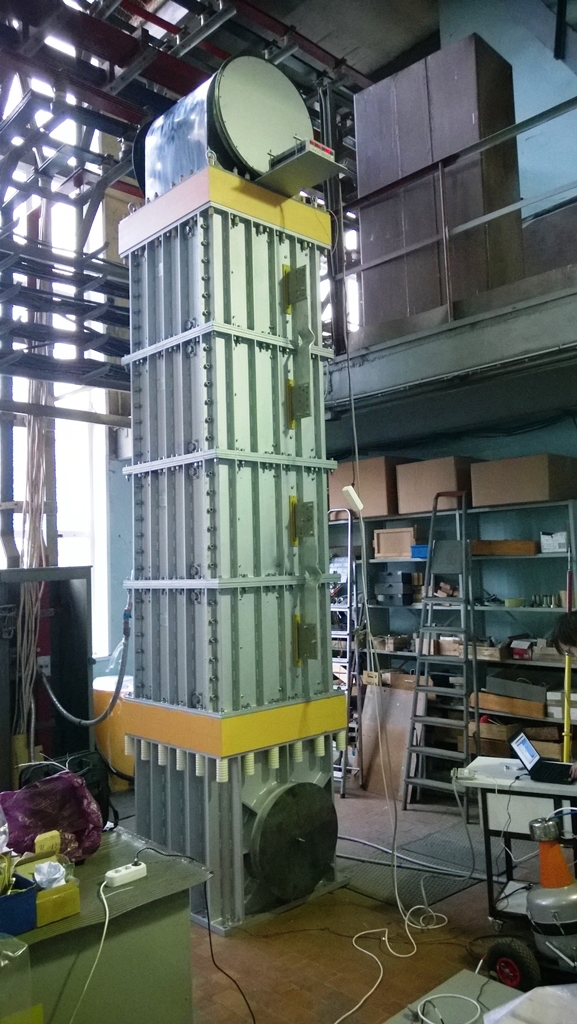
SNU is in reality - the red and blue cylinders are FOS and FDS, and from the bottom you can see the boxes TH1, TH2 and pneumatic automation.
Uff. Probably it will be clearer if you explain how it works:
So, initially the current flows through closed FOS and FDS.
1. First, the RMS closes, connecting the SNR resistor in parallel - however, since the resistance of the main current circuit is much less, nothing happens.
2. Further, pneumatics during a time less than 5 ms open FOS, and for the first time the current is shifted by 0.25 ms to the surrounding thyristors T (this is necessary to prevent the arc).
3. At the same time, the thyristor switch TH1 is activated, discharging the capacitor C1 through the connection point L1 and FDS, and leading to zeroing of the current through the thyristors T and FDS.
4. All current through the device is transferred to the thyristor group TH1, allowing you to open the FDS, which is needed to isolate the FOS thyristors from the voltage of 8.5 kV, which will appear at the moment of current transfer to the energy extracting SNR resistor.
5. After discharging C1 and opening FDS, you need to close TH1 - for this, the second chain C2 - TH2 is used (and the diode D1 is needed, respectively, to short circuit C1).
6. After that, the coil current will flow through the SNR resistor, creating the desired voltage surge.
I hope this was understandable :) One of the key features of this switch are ultrafast pneumatic disconnectors and closers (FOS, FDS, FMS) - which work about 10 times faster than conventional electrical circuit breakers.


FOS, FMS and FDS in models and live. Pleases quite high-quality performance of these devices.
Along with the prototype of the serial SNU, its control system was tested (a post about the organization of the ITER equipment management system as a whole), as you know, two buttons or a toggle switch (this is ITER) cannot be dispensed with, and the control scheme consists of 2 modular PLCs and several switches.

It's funny that several years ago a similar device was developed by ABB concern for completely different purposes - for cutting off the branches of high-voltage direct current lines. Although the ABB hybrid switch is somewhat different (very high voltage at moderate current), its development was presented as a revolution in power transmission solutions using direct current transmission lines .
Electrical wiring of the ITER magnets power supply system, including switching equipment.
Today there is a small story about systems that will quickly connect and disconnect ITER superconducting coils and another engineering complexity, especially since in March they passed qualification tests of devices that perform this task.
')
For a start - a little about the electric system of the ITER magnetic system. The international tokamak will have 48 superconducting magnets, namely:
- 18 toroidal coils (TF) electrically connected in series, but having one quick energy release device (FDU) for each pair of coils
- 6 central solenoid (CS) modules connected independently
- 6 poloidal coils (PF) connected independently
- 9 pairs of correcting coils (CC) connected independently
ITER magnetic system diagram
As you can guess, an independent connection is needed to create a different current (= magnetic field strength) in different coils in order to control the plasma (its position, shape, current, etc.). Current control is carried out in two ways: firstly by a set of powerful rectifiers (tens of megawatts, in the total of the order of 250), which smoothly create and change the current in the coils, and secondly by inserting a short resistor (of course, mega-resistors with a total capacity of 2.5 gigawatts (! ), this is ITER) into the coil circuit, in order to remove some of the energy from it.
Slightly more detailed scheme of connecting ITER magnets to power sources.
Resistor insertion operations are a classic way to start a tokamak. In this case, a sharp change in the field in the poloidal coils and the central solenoid creates a vortex electric field that breaks through the plasma and induces an annular current in it, which is part of the plasma confinement system.
One ITER resistor assembly module - 2-megawatt steel with air cooling
Today’s hero, SNU (Switching Network Unit), who was tested at NIIEFA in March 2017 (well, and who is more interested, more about the ITER magnet power supply system ) is responsible for introducing resistors into the coil circuits. In total, 8 SNUs will be installed in ITER (on CS and PF1 and PF6 coils).
The main difficulty in creating SNUs is currents up to 60 kiloamperes and a large inductance of switched coils, which leads to the appearance of a voltage of 8.5 kilovolts at the moment of breaking the contacts. Considering the still extremely low resistance of the circuits, the arc in the switch turns out to be ignited with a current of 60 kA, which instantly puts it into an unsuitable state. And we need a switch resource of 30 thousand shutdowns.
Dead end? No, we can do everything much more difficult!
This is the SNU scheme. Unfortunately, we have to understand numerous abbreviations, but we will try: So, SNR are the same resistors that are inserted into the coil circuit, first they are parallel to the circuit through which current flows from the rectifier to the coil formed by the FOS and FDS breakers. At the bottom there is a thyristor counterpulse module TCB, made of two identical circuits TH1, TH2, and in parallel with FOS and FDS - FMS contactors and EPMS emergency pyroseal switch.
SNU is in reality - the red and blue cylinders are FOS and FDS, and from the bottom you can see the boxes TH1, TH2 and pneumatic automation.
Uff. Probably it will be clearer if you explain how it works:
So, initially the current flows through closed FOS and FDS.
1. First, the RMS closes, connecting the SNR resistor in parallel - however, since the resistance of the main current circuit is much less, nothing happens.
2. Further, pneumatics during a time less than 5 ms open FOS, and for the first time the current is shifted by 0.25 ms to the surrounding thyristors T (this is necessary to prevent the arc).
3. At the same time, the thyristor switch TH1 is activated, discharging the capacitor C1 through the connection point L1 and FDS, and leading to zeroing of the current through the thyristors T and FDS.
4. All current through the device is transferred to the thyristor group TH1, allowing you to open the FDS, which is needed to isolate the FOS thyristors from the voltage of 8.5 kV, which will appear at the moment of current transfer to the energy extracting SNR resistor.
5. After discharging C1 and opening FDS, you need to close TH1 - for this, the second chain C2 - TH2 is used (and the diode D1 is needed, respectively, to short circuit C1).
6. After that, the coil current will flow through the SNR resistor, creating the desired voltage surge.
I hope this was understandable :) One of the key features of this switch are ultrafast pneumatic disconnectors and closers (FOS, FDS, FMS) - which work about 10 times faster than conventional electrical circuit breakers.
FOS, FMS and FDS in models and live. Pleases quite high-quality performance of these devices.
Along with the prototype of the serial SNU, its control system was tested (a post about the organization of the ITER equipment management system as a whole), as you know, two buttons or a toggle switch (this is ITER) cannot be dispensed with, and the control scheme consists of 2 modular PLCs and several switches.
It's funny that several years ago a similar device was developed by ABB concern for completely different purposes - for cutting off the branches of high-voltage direct current lines. Although the ABB hybrid switch is somewhat different (very high voltage at moderate current), its development was presented as a revolution in power transmission solutions using direct current transmission lines .
Source: https://habr.com/ru/post/403729/
All Articles