SNR-ERD: From a “ping” machine to a line of equipment

The beginning of the two thousandth is the rapid development of telecommunications networks. The installers, who spent the whole day on the roofs, laying the cable to the final subscriber, urgently needed devices to check the conformity of the cable to the connected port. The problem of “freezing” of equipment was also acute. The installers had to constantly ply between communication nodes and reboot them manually. So the idea of developing the first SNR-ERD .
As a result, the specialists from “NAG” came up with the idea of creating a device that could be connected to the cable and ping a specific port. A little later, the device was equipped with the function of remote rebooting the device. This is how SNR-ERD-WEB appeared, which became a universal assistant for installers and network administrators.
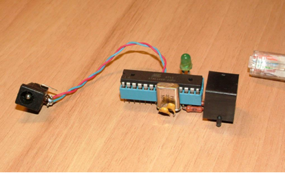
First ping
')
The first model was an eight-bit microcontroller with 8 kilobytes of flash memory and 500 bytes of RAM. The device was controlled via a web interface. The device could work with temperature sensors, reboot the equipment and control the door opening-closing sensors.
The device has found the audience quickly enough. Development and improvement of the device occurred regularly. And most of the recommendations came from ERD buyers, who used the device in the field and understand what improvements it needs. Already in the next modification, the device received the SNMP protocol, remote firmware upgrade, thermostat function, phase sensor.
The great demand for the device spawned the development of a number of devices whose functionality was constantly expanding. The next step in this chain was SNR-ERD-2 , which is still positioned as a budget tool for controlling data center parameters, and its modifications are in great demand.
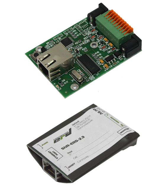
An inexpensive compact device with growing functionality enjoyed fairly good demand, which resulted in the development of a whole series of devices with a general index of SNR-ERD-2. These devices are still positioned as a budget tool to control the basic physical parameters in mini-DPC .
ERD-2 has been widely used by telecom operators for monitoring temperature in data centers (Data Centers). For example, Mail.Ru Group has installed more than 800 ERD-2 pieces.
Here is a review by Deputy Technical Director of the Mail.Ru Group, Sergey Kubasov:
“We use ERD-2 to monitor the temperature in the data centers M100 (Mail.Ru Group) and ITSVA (Vkontakte). When choosing a solution for us it was important:
Price - in the case of ERD, the cost of one temperature sensor (together with the controller) is one of the lowest;
Peripherals - for ERD it is enough to have any L2 switch, there is no need to buy any additional controllers for aggregations;
Deployment rate - the product API is described in as much detail as possible;
Delivery time - regardless of the volumes we requested, the shipment was carried out “on the next day” or at a time acceptable to us;
Production flexibility - small customization in the form of an increase in the length of the cable of the thermal sensor, was performed promptly and without additional questions;
High reliability - for the entire period of operation I want to note a very low reject rate and the almost complete absence of failure;
Support - we get answers on problems very quickly.
What is missing:
PoE - you have to pull food, which is very inconvenient;
Humidity sensors - then we could have complete climate control on the ERD. ”
Client requests could not go unnoticed and after a while NAG specialists developed a third series device. In addition to the already known functions, ERD-3 added:
- RS-232 and RS-485 serial data interfaces;
- additional phase sensor;
- external port for connecting up to five 1-Wire sensors (SNR-DTS-2);
- the ability to install a GSM / GPRS module to implement a wireless data transmission channel, as well as sending SMS notifications;
- Passive PoE with 5V power supply.
Changed and device design. The device was placed in a convenient metal housing and DIN rail mounting.
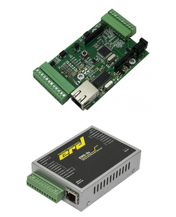
ERD-3 are 3-in-1 devices: an Ethernet / RS232 or Ethernet / RS485 interface converter, a UPS (Uninterruptible power supply) controller with MegaTec protocol support, as well as a device for monitoring the status of sensors, medium temperature and voltage.
By the way, quite recently ERD-2 was also produced in a metal case, which was a response to requests from integrator companies that were ready to build their solutions based on ERD, but the appearance of the device did not quite match their needs. Therefore, now ERD-2 can be purchased in two versions: in heat shrinkage or metal case.

Advanced ERD-2
Let's return to ERD-3 . In addition to the widespread demand from providers, the device is demanded by integrators for small automation and the system of Automatic Metering System as an Ethernet / RS-485 and Ethernet / RS-232 for polling various resource counters. On the basis of ERD devices, the software load “NAgruzka”, about which we wrote earlier, works.
In the future, ERD-3 was enhanced by the GSM / GPRS module for use in solutions where GSM / GPRS was the main data transmission channel. The device received the name ERD-GSM.
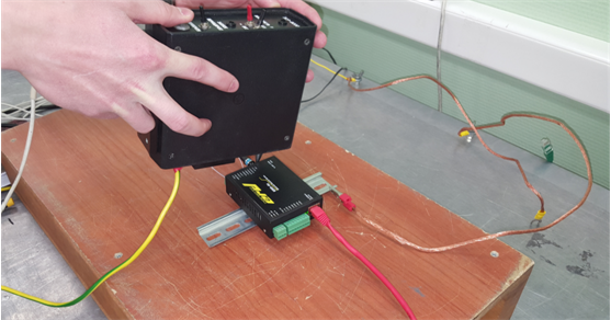
ERD-GSM heat resistance test
However, time did not stand still and it became clear that modern requirements dictate the further development of the ERD device series, and for this new computational and hardware resources were needed.
The 32-bit STM32F407 microcontroller from ST and the modern KSZ8031RNL PHY controller were chosen as the basis for the new hardware and software complex to work with the Ethernet network. In connection with the change of platform, it was necessary to completely rewrite the software. At the same time, it was decided to transfer functional software under the control of the real-time operating system RTOS. The operating system allowed unleashing the control loop and building a function call based on flexible priorities. Also, the device was able to power, both through external dedicated contacts, and PoE standards IEEE 802.3af-2003 and IEEE 802.3at-2009, as well as Passive PoE from 36 to 48 V.
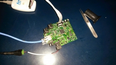
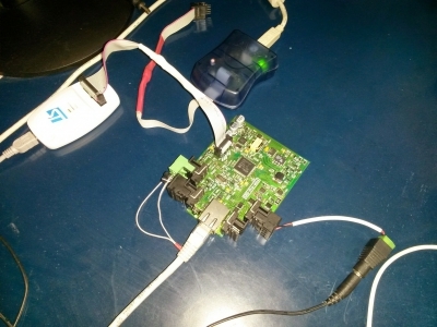
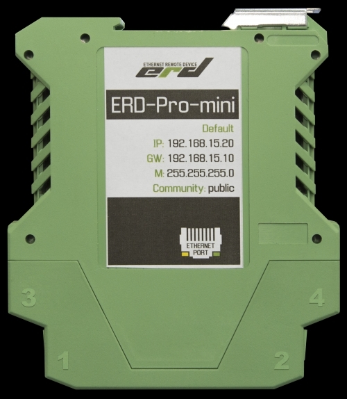
The transition to the new platform was carried out in several stages. At first, a device with basic equipment, called ERD-Pro-mini, appeared on the light. The first devices were going to artisanal in the laboratory "NAG".


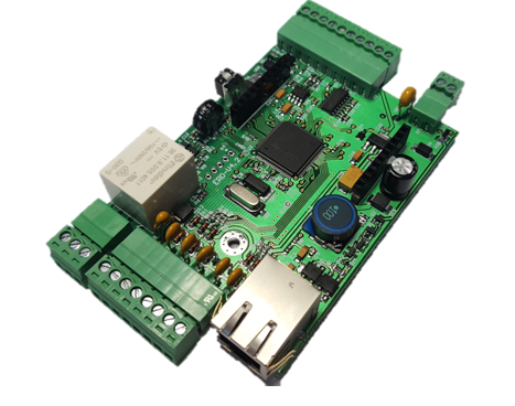
Now the device looks like this:
All the advantages of ERD-Pro-mini were somewhat lost against the background of the shortcomings that were found already in use. Due to the specifics of the case, an erroneous supply of power to the contacts, which were not designed for this, occurred, which, in turn, led to irreversible damage to the device.
One of the main advantages of the ERD-3 was its enclosure itself, as well as the possibility of modular expansion and the availability of RS-232 and RS-485 interfaces, and the bottleneck was the 8-bit ATmega328 controller with its 32 KB of flash memory versus 1024 KB have STM32F407. If the client asked to implement any new feature, then for this it was necessary to cut out some other one. Thus, the task of combining the best of ERD-3 and ERD-Pro-mini appeared.
The ERD-3 PCB is almost one and a half times smaller than the ERD-PRO-mini board. Therefore, the density of the electronic components was significantly higher, and therefore the requirements for manufacturing the board became higher. It was not a difficult task, but with direct development, it turned out that the new device should have a number of additional features, in addition to those already present in ERD-3 and ERD-PRO-mini.
On board the device required to place:
- protection against polarity reversal;
- boost DC / DC converter 12V, to power external sensors;
- 5V DC / DC down converter, compatible with PoE standards;
- backup circuits with PoE power and a dedicated power connector;
- Precision DAC (DAC), for performing the function of PID regulation;
- powerful power relay for switching loads with voltage up to 250 V and current up to 10 A;
- five combined input and output ports, the so-called DIO ports (digital input / output);
- resettable fuses to protect DIO ports and DAC ports,
- additional external non-volatile memory for storing settings and measurement results.
Plus, the new device had to provide an average time between failures of 75,000 hours and also meet the requirements for resistance to electromagnetic effects for information technology equipment, according to GOST CISPR 24-2013.
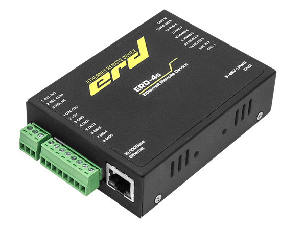
As a result, the light saw "Multifunctional controller SNR-ERD-4" or simply abbreviated ERD-4.
In the process of developing ERD-4, it was necessary to design a schematic diagram, select components and make samples that were subjected to various experiments. For example, the test for resistance to air electrostatic discharges with a voltage of 8 kV.
To comply with GOST CISPR 24-2013, experiments were conducted with the device's resistance to various types of interference.
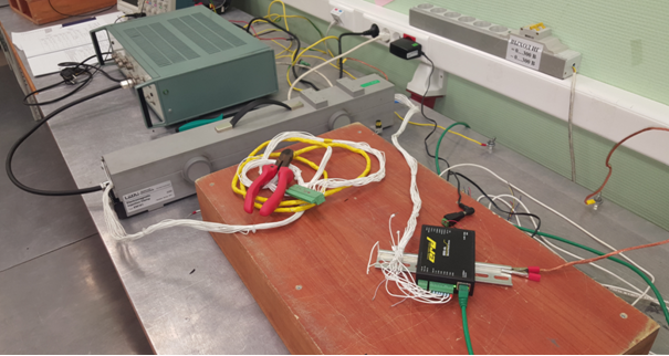
ERD-4 Test for Nanosecond Pulse Interference Resistance

ERD-4 test for resistance to high energy microsecond pulses
The device was tested in climatic chambers. Limit voltages and currents were measured. After going through dozens of samples, repeatedly tested, this is the final form of the printed circuit board.
We should also dwell on the description of the operation of the DIO ports and the DAC output.
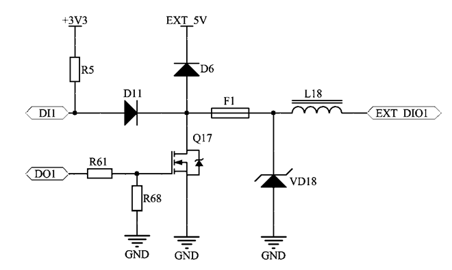
Fragment of DIO port concept
The feature of their implementation is that each port can work as an input (DI mode), and an output (DO mode). This is achieved by the fact that the microcontroller is connected to each port with two GPIO pins through special decoupling circuits D11 and Q17. This solution has increased the flexibility of ERD-4. The user can now determine the necessary port configuration. For example, the “5 inputs + relay” configuration will be useful in those applications where you need to connect a large number of sensors with a relay output (perimeter security, control of water leaks). The relay in this configuration may include a siren or groundwater pump. If the user needs to control a large number of relays, contactors or starters, he can use the configuration of "5 outputs + relay". Between these two extremes, any intermediate configurations are possible: “2 inputs + 3 outputs”, “4 inputs and 1 output”, etc.
Also, for the first time in the ERD series, the ERD-4 outputs can switch loads with supply voltage up to 48V and with rated / pulse current up to 0.5 / 1A. This allows you to significantly expand the possibilities of pairing ERD-4 with external switching devices and loads. In particular, widely used 12 V and 24 V relays can be used. If it is planned to use five-volt switching devices, such as SNR-SMART sockets, the built-in voltage source allows supplying loads with total current up to 2 A.
Especially for ERD-4, two mezzanine radio modules were developed. One for work with GSM / GPRS, and another - for ISM networks in the 868 MHz range.
GSM / GPRS module allows you to make a backup connection via GSM / GPRS and control via SMS. The module for ISM 868 networks allows you to connect various wireless sensors, such as pulse counters, heat meters, phase sensors, etc.


Now SNR-ERD is a whole line of devices demanded by telecom operators, integrators of automated systems, enterprises of the housing and utilities sector, banking structures and IT companies. Devices are used at communication centers, in data centers, in various cabinets with equipment for automating environmental monitoring, perimeter monitoring, as well as for solving telecontrol tasks of various loads.
Source: https://habr.com/ru/post/403409/
All Articles