We go down - we grow up, or axis Z for cheap
Good day to you, dear geeks and sympathizers! This publication is a continuation of the description of the design of my homemade 3D printer. The Z axis is one of the most controversial printer nodes. What to choose - the ultimate accuracy or good scaling? Move the x-axis or printer desktop? Two approaches - two solutions.
I could not look at the first 3D printers without a shudder: the structures were immature, many nodes were used in violation of specifications, because of the general fluctuation, constant adjustment was required, minor repairs, the size of the working field was small. I decide to solve the problem of internal contradictions, simply by crossing the
The skeleton of the 3D monster was designed and twisted together:
')
It consists of forty-millimeter aluminum construction profiles connected by thick corners 45x45 and bolts M8. This design has dimensions of 60x40x40 cm and is absolutely unshakable during normal operation of the printer. The size of the working platform was 45x22 cm, with a maximum object height of 28 cm.
The Z axis is formed by two vertically positioned twenty-millimeter linear tires with precision carriages. The carriages are driven by precision trapezoidal screws mounted on angular contact bearings. Each screw is driven by a stepper motor through a 3: 1 belt drive. The upper ends of the screws are turned and inserted into the needle bushings so that the axial displacement of the screw in the sleeve prevents it from wedging during thermal expansion. I used a polymer nut for screws: there are no high speeds / loads, and the polymer nut is not so demanding for lubrication and much easier to install. In this design, the height of the model is increased by raising the X axis above the table, and the Z axis is used as a movable support for the X axis.

Video of work:
This axis worked without any problems until dismantling this printer for parts.
Disadvantages of this solution:
1. Price. Precision components are expensive.
2. The complexity of the design
3. Poor scalability.
When I began to build a second printer, experience and stinginess were involved in creating the design along with the innate desire to go their own way, not expecting favors from nature.
Accordingly, the new printer was supposed to be not only simpler, faster, more versatile, reliable and maintainable, but also significantly cheaper.
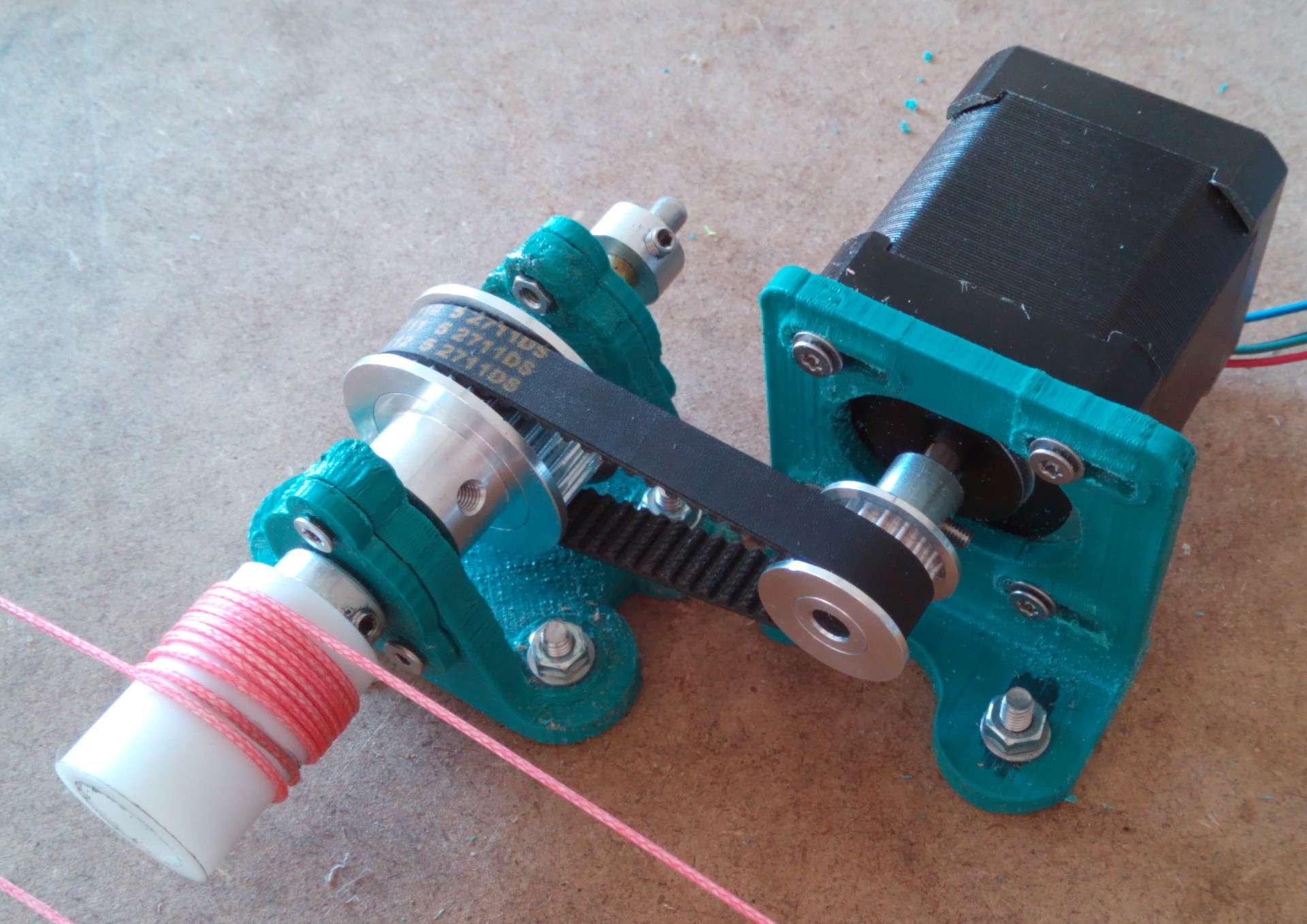
For the Z-axis of the new printer was chosen not a screw drive, but a cable construction similar to the winch of cargo cranes. It consists of the actual drive mechanism with a belt reduction gear and two blocks, on which the whole mass lies on the Z axis.
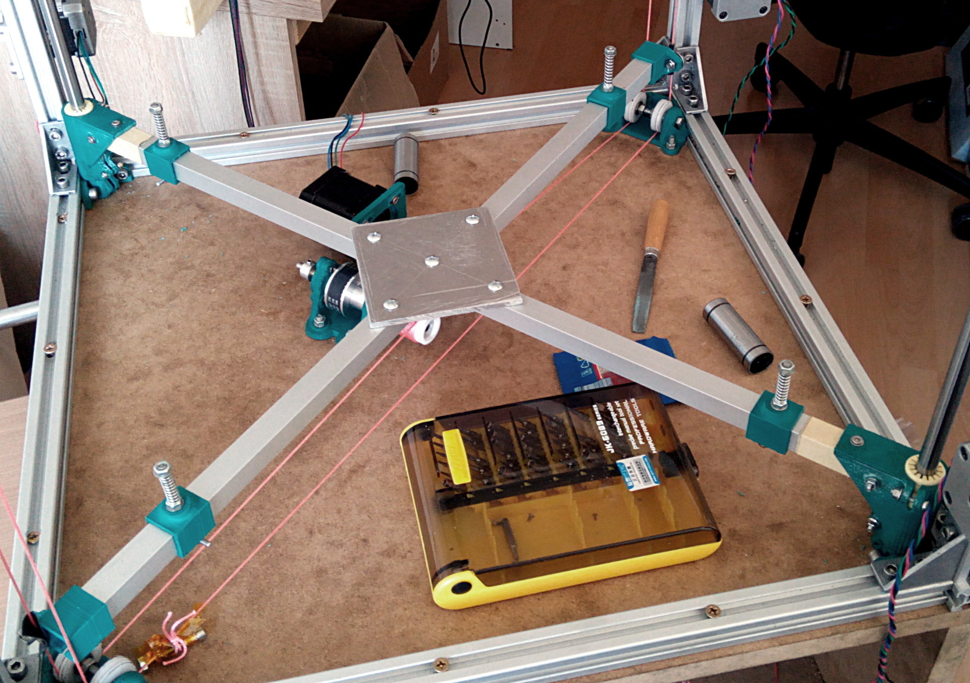
Here is a photo of the printer as a whole:
Two ten-millimeter steel tires are responsible for the stability of the spatial orientation, along which paired friction bearings of synthetic bronze are moved.
In the following two videos you can see the design of the winch, there is nothing complicated:
Wreck of the Z axis: simple and lightweight design.
Power calculations: The drive drum has a radius of 10 mm. Accordingly, a torque of 0.3 Nm (conventional Nema 17 motor) on a lever of 10 mm will be 30 N. A belt gearbox with a 2: 1 gear ratio doubles that number.
As a result, the maximum force that this winch can develop is about 60 Newton, respectively, the maximum mass of the Z axis, together with the masses of the table and the object, should not exceed 6 kg at rest.
Now we determine the loss of acceleration and deceleration of the Z axis: to accelerate 1kg mass with an acceleration of 1 m / s², you need to apply a force of 1 Newton. In fact, the acceleration of 1 m / s² for the Z axis is sufficient, and each kilogram accelerated will cost us 1 N of applied force.
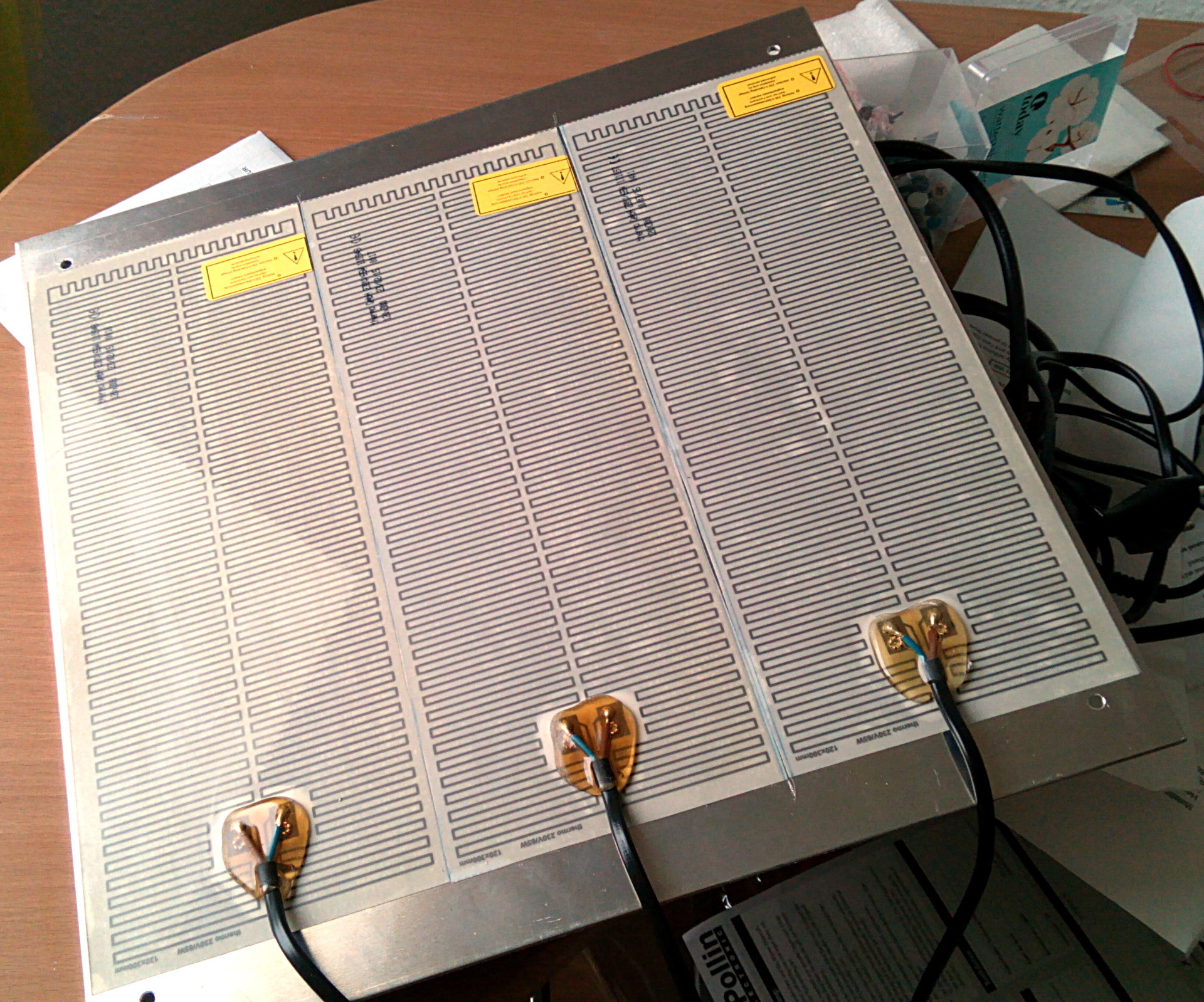
The heaviest element in the design is a heated table, this is a duralumin plate 350x350x3 mm weighing 980 grams with glued heating elements with a total weight of 150 grams.
The remaining structural elements, including thermal insulation from Basotect, weigh about 900 grams.
The total weight of the structure is about 2030 grams, which, when rounded up, will require 21 N to hold and another 2.1 N to accelerate. Total, rounding again in the direction of large values, 24 N.
If the kilogram model is added to the mass of the Z axis, then 34 N will be needed, which is
a little more than half of the estimated power of the winch. It would seem that the design is excessive in power. But the devil, as always, is in the details. The fact is that in order to achieve maximum torque, maximum currents must flow through the motor windings, which will inevitably cause its overheating and premature failure.
For this reason, I designed the design with the condition of a large power reserve, and installed the motor current by experience a little more than the minimum required. The motor at the same time heated up to 50-60 ° C, which is quite permissible according to specifications.
In this video, the winch easily juggles the Z axis without a desktop, but with two filament coils weighing 1300 grams each:
So, the power issue is resolved. Now let's talk about accuracy. Taking into account the parameters of the components of the winch and the motor, with a 1/16 microstepping it is possible to move the Z axis in increments of 0.02 mm. Now consider the problem of accuracy in a winch with a single-layer winding cable. The radius of the drive drum in my design is 10 mm, respectively, the circumference when winding will be 62.8 mm. In order to raise the Z axis by 44 cm, it takes about seven turns. When using a cable with a thickness of 1 mm, the axial winding offset will be 7 mm. When this happens, the change in distance from the point of contact of the cable with the drum to the lower support block.
Let's calculate how bad everything is: the lead drum is located in the center of one of the diagonals of the square formed by the lower part of the printer case. Accordingly, the drum is 320 mm away from each of the lower support blocks. By simple calculations, it turns out that when the table is moved by 440 mm, the drive geometry will change by 0.077 mm.
Quality trapezoidal screws ensure accuracy from 0.07 to 0.4 mm at such distances. Simply put, do not provide any significant gain in accuracy. If for some reason you need to print models with a height greater than 44 cm, you just need to proportionally increase the diameter of the drive drum (to maintain the small number of revolutions required to move the axis) and the gear ratio (to maintain the nominal load on the motor). At the same time, the cost of the mechanism grows slightly, unlike the construction with a screw drive.
One of the test objects:
In conclusion, I can say: although experience is a derivative of the difficulties and mistakes made, but sometimes the process of its acquisition gives more pleasure than the results achieved.
There will be no 3D models, because I can’t find them on the disk.
Published under the WTFPL license.
Well, and traditional: Have fun!
Source: https://habr.com/ru/post/403227/
All Articles