Review of the Arduino / Robotics online course from MIPT (second week)
We continue to publish a review of the online course “Building robots and other devices on the Arduino”, start here .
So, how long is short, the second week of the online course of robotics from MIPT is over . Frankly, the week turned out to be very rich with all sorts of topics.
Here is a sample list that I have allocated for myself:
- Voltage divider Using a photoresistor and thermistor
- Analog signal. Signal width
- Data exchange through the serial port. Wednesday Processing
- Digital signal Buttons and connection options. Pull-up resistor
- Boolean expressions, if and else statements
- Buzzer, LED scale, seven-segment indicator
- ICs. Logic inverter 74HC04, shift register 74HC595
- Debugging programs
- External modules
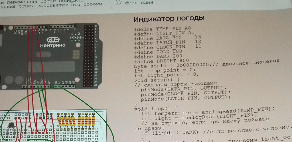
- Option of a ready monitoring system that displays the temperature and the level of illumination on the LED scale, as well as the speaker, which is triggered when a certain temperature is exceeded
Successfully passing the test and collecting the proposed schemes from the lessons, I thought about how to improve this or that scheme or collect something of my own.
The first thing that came to mind was the modernization of the light sensor. The implementation suggested in the lesson simply took the value off the photoresistor and sent it to the serial port.
The upgraded version should use a seven-segment indicator to display numbers from 0 (minimum illumination) to 9 (maximum illumination). The indicator must be connected via a shift register. With the help of two buttons should be set the minimum and maximum levels of illumination. The shift register is needed in order not to use the Arduino pin on each segment, but instead to do with a smaller number of pins. In fact, the shift register converts serial data output (one bit per unit of time) into parallel (several bits per unit of time). In our case, instead of the seven pins of the Arduino, we need only three.
In the editor Fritzing I got such a device.

Thus it looks live.

Schemes of work with a shift register and a photoresistor were taken as a basis.
Note that on the board the photoresistor is connected slightly differently than in the video lesson - there we took the voltage value on the photoresistor relative to the ground, and in the circuit we removed the voltage drop relative to the power supply. This is done to simplify the program a little - with increasing light level the resistance of the photoresistor decreases. Consequently, at the same current the voltage drop decreases. Therefore, the analog input will be the higher the voltage, the higher the light level, and vice versa.
Now it's up to you - to modify the source code. The basis was the same program for outputting the value to a seven-segment indicator.
// , #define DATA_PIN 13 #define LATCH_PIN 12 #define CLOCK_PIN 11 // , #define BTN_MIN 3 #define BTN_MAX 2 // , #define SENS_PIN A5 // , byte d0 = 0b01111101; byte d1 = 0b00100100; byte d2 = 0b01111010; byte d3 = 0b01110110; byte d4 = 0b00100111; byte d5 = 0b01010111; byte d6 = 0b01011111; byte d7 = 0b01100100; byte d8 = 0b01111111; byte d9 = 0b01110111; // int min_light = 0; int max_light = 1023; // int value; // , . . int output; // int digit; void setup() { // pinMode(DATA_PIN, OUTPUT); pinMode(CLOCK_PIN, OUTPUT); pinMode(LATCH_PIN, OUTPUT); // Serial.begin(9600); // pinMode(BTN_MIN, INPUT_PULLUP); pinMode(BTN_MAX, INPUT_PULLUP); } void loop() { // value = analogRead(SENS_PIN); output = value; // - if (!digitalRead(BTN_MIN)) min_light = value; if (!digitalRead(BTN_MAX)) max_light = value - 10; // if (value < min_light) output = min_light; if (value > max_light) output = max_light; // , digit = map(value, min_light, max_light, 0, 9); // Serial.println("Value: " + String(value) + " Output: " + String(output) + " Min: " + String(min_light) + " Max: " + String(max_light) + " Current : " + String(value) + " Digit: " + String(digit)); // if (digit == 0) { digitalWrite(LATCH_PIN, LOW); shiftOut(DATA_PIN, CLOCK_PIN, LSBFIRST, d0); digitalWrite(LATCH_PIN, HIGH); } else if (digit == 1) { digitalWrite(LATCH_PIN, LOW); shiftOut(DATA_PIN, CLOCK_PIN, LSBFIRST, d1); digitalWrite(LATCH_PIN, HIGH); } else if (digit == 2) { digitalWrite(LATCH_PIN, LOW); shiftOut(DATA_PIN, CLOCK_PIN, LSBFIRST, d2); digitalWrite(LATCH_PIN, HIGH); } else if (digit == 3) { digitalWrite(LATCH_PIN, LOW); shiftOut(DATA_PIN, CLOCK_PIN, LSBFIRST, d3); digitalWrite(LATCH_PIN, HIGH); } else if (digit == 4) { digitalWrite(LATCH_PIN, LOW); shiftOut(DATA_PIN, CLOCK_PIN, LSBFIRST, d4); digitalWrite(LATCH_PIN, HIGH); } else if (digit == 5) { digitalWrite(LATCH_PIN, LOW); shiftOut(DATA_PIN, CLOCK_PIN, LSBFIRST, d5); digitalWrite(LATCH_PIN, HIGH); } else if (digit == 6) { digitalWrite(LATCH_PIN, LOW); shiftOut(DATA_PIN, CLOCK_PIN, LSBFIRST, d6); digitalWrite(LATCH_PIN, HIGH); } else if (digit == 7) { digitalWrite(LATCH_PIN, LOW); shiftOut(DATA_PIN, CLOCK_PIN, LSBFIRST, d7); digitalWrite(LATCH_PIN, HIGH); } else if (digit == 8) { digitalWrite(LATCH_PIN, LOW); shiftOut(DATA_PIN, CLOCK_PIN, LSBFIRST, d8); digitalWrite(LATCH_PIN, HIGH); } else if (digit == 9) { digitalWrite(LATCH_PIN, LOW); shiftOut(DATA_PIN, CLOCK_PIN, LSBFIRST, d9); digitalWrite(LATCH_PIN, HIGH); } // delay(10); } Of the features - when setting the maximum level of illumination, we had to subtract some constant (max_light = value - 10), chosen empirically. This is necessary in order to avoid “rattling” at the maximum level of illumination, since the voltage value taken from the photoresistor is unstable.
Compile the sketch, load into the Arduino and check.
First in the port monitor ...

And then live
As you can see, the device successfully works in the form as it was described. Of course, there is still room for improvement — for example, you can add a beep when the lighting falls below a certain level - this will mean that you need to turn on additional lighting in the workplace. Also in the future it will be possible to change the program itself, using arrays and additional functions.
In conclusion, I repeat once again that the week turned out to be very rich on various topics. Note that since the publication of the course in the Arduino IDE, the built-in function Serial Plotter has appeared, which partially overlaps the Processing functions considered in the lessons. Also at the end of the week, the authors came to the idea of modularity, when the end device is assembled from ready-made elements — modules, for example, buttons with an already built-in pull-up resistor, a ready-made light sensor, where the photoresistor and the usual resistor are already assembled into a voltage divider, and the like. However, the device can be easily assembled on a breadboard, which was done. Question to readers, did you have to build your own case for your devices? What materials did you use for this? Maybe cardboard, plywood, plexiglass or, what is not uncommon today, were printed on a 3D printer?
')
Source: https://habr.com/ru/post/403029/
All Articles