MPTU-2-48
Today I want to tell a little and, most importantly, lay out a scan of the documentation on a very successful, in my opinion, Soviet PLC - a microprocessor-based programmable cyclic device, abbreviated MCPU-2-48, manufactured by VAZ.
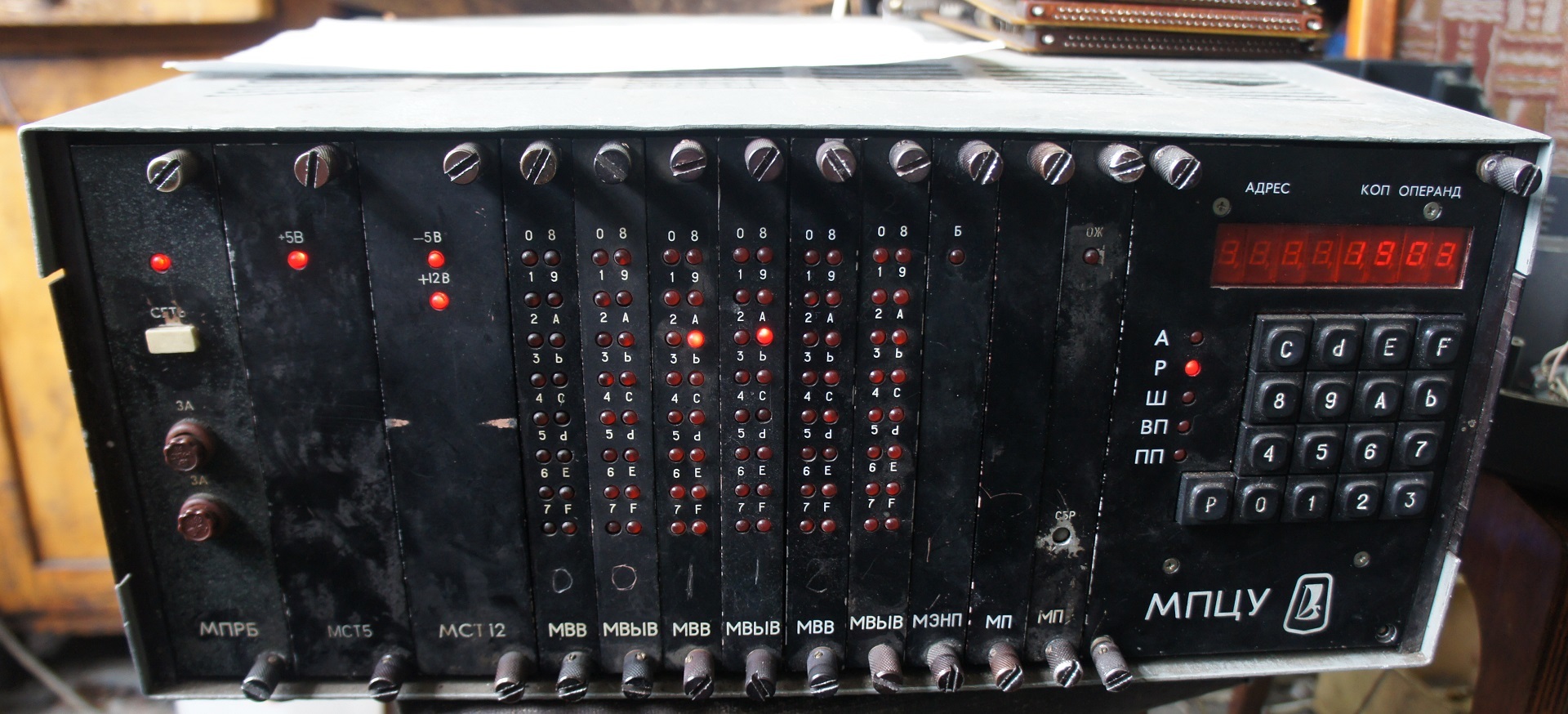
General form.
I work as an electronics engineer in the wreckage of a once-large factory for the production of valves and pushers, whose machine park is a wild technology vinaigret from the 60s of the last century to the present day. Such a rarity still works on a pair of machines, it is built on the basis of a kr580 processor, up to 2 kb of user RAM on KR188RU2A, 256 bytes of service RAM, up to 48 discrete inputs / outputs (24v, 0.5a). Entering the work program is possible through the remote control on the MPCU itself, or through a PC via RS-232 interface. Safety of the entered program at power off is provided by 3 \ 6 AA elements. Small mentions in the network of this device are mainly related to using it as a controller of an industrial robot, this was also at our factory, but, like many other equipment, went to scrap. When debugging the machine is very useful and convenient ability to manually enable a particular port. The command system is sharpened by the implementation of the flowchart, which is also very convenient for simple programs.
')
A detailed description of the work in the documentation allowed my predecessors to remake the memory module into the programmer of ROM RF1 \ RF2 with processing programs, as well as create a “Frankenstein” - only 4 blocks remained in the frame - processor, memories with modified ROM, with a wired user program, input modules and output. Power +5 \ +12 \ -5 served from an external source, the start command is automatically given when turned on using a capacitor with a resistor, plugged in instead of the control panel, the user RAM block is missing.))
With the exception of BP, failing due to drying capacitors, the device is quite reliable and trouble-free.
In the near future I will try to upload the dumps of the ROM.
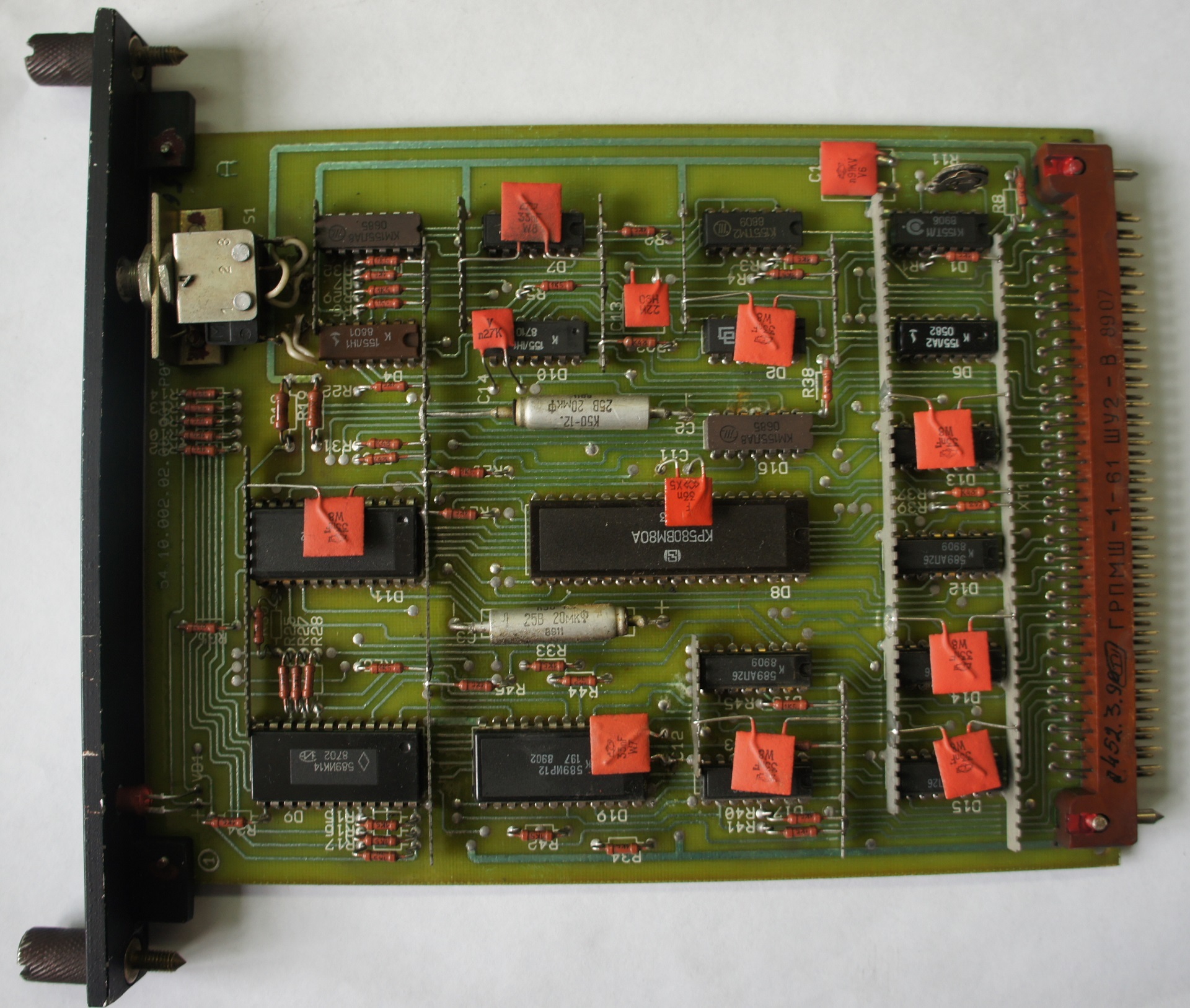
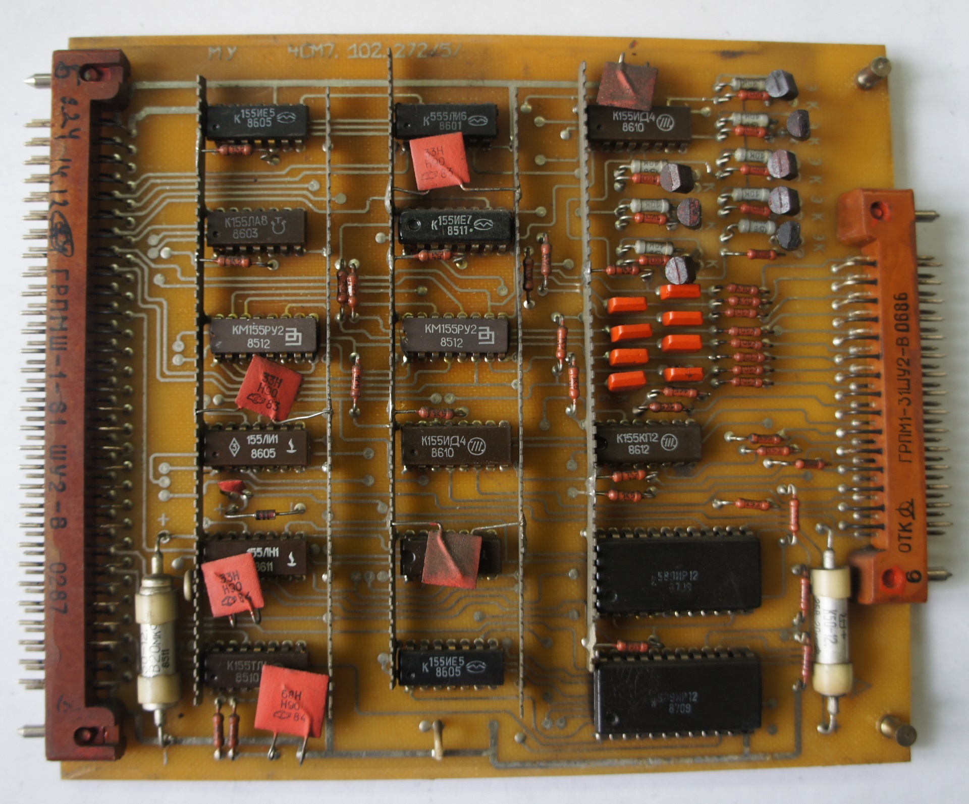
Processor module
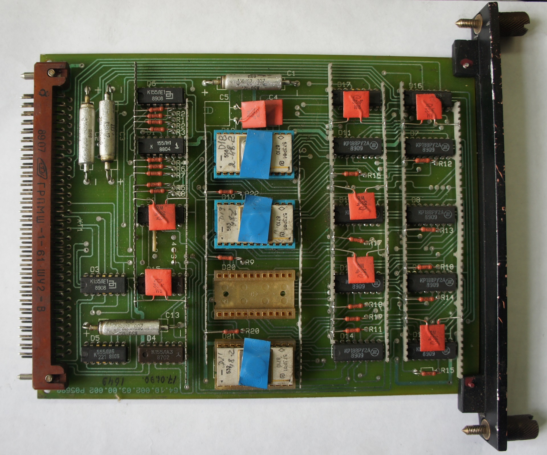
Memory module - ROM and service RAM
User RAM Module, 512B
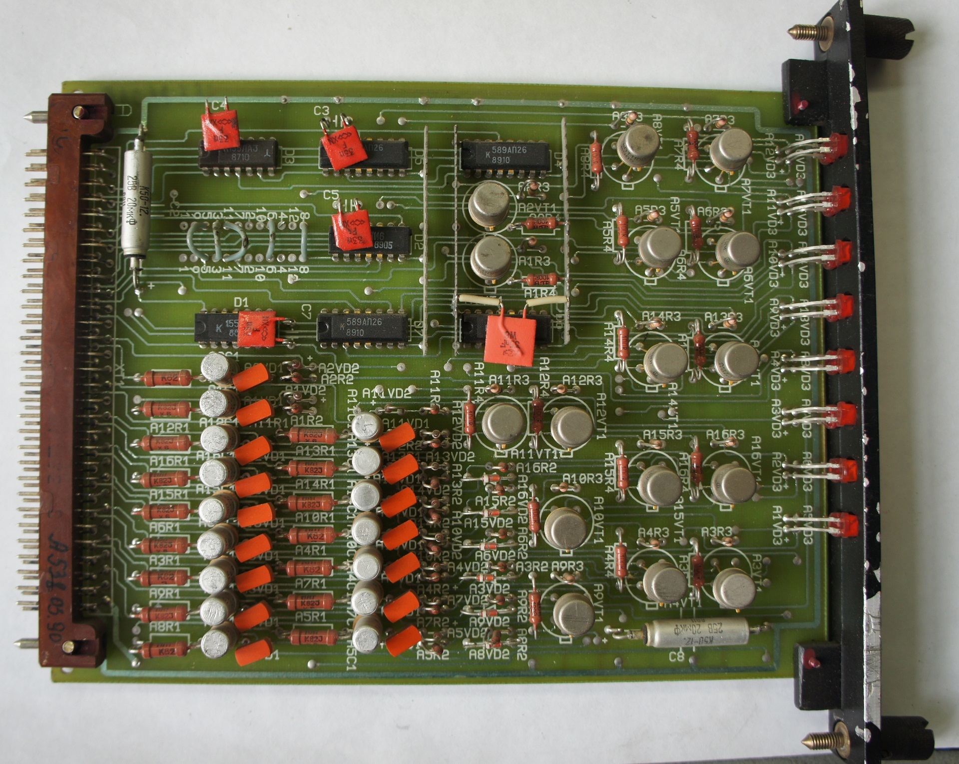
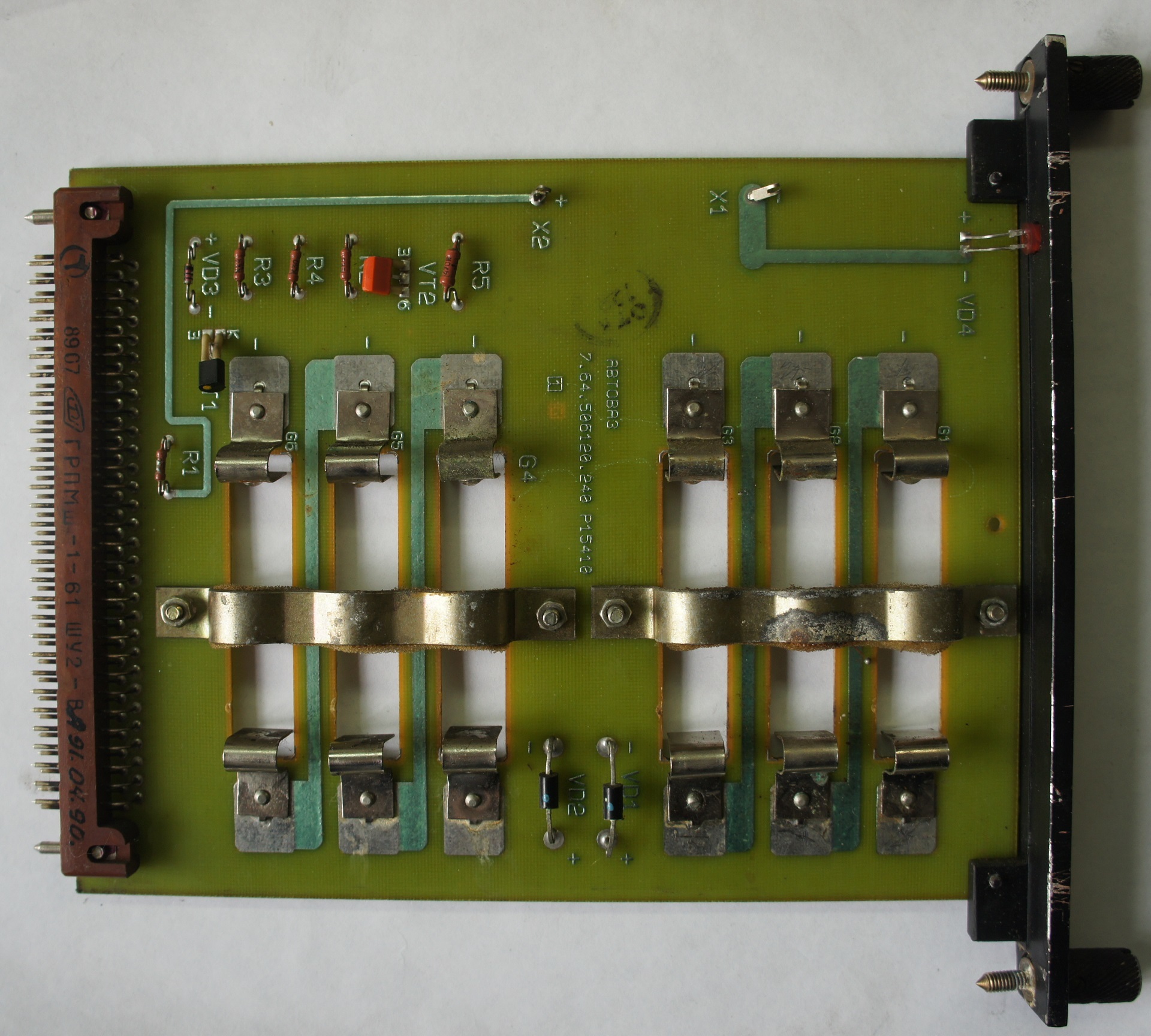
Output module 16 * 24V * 0.5A
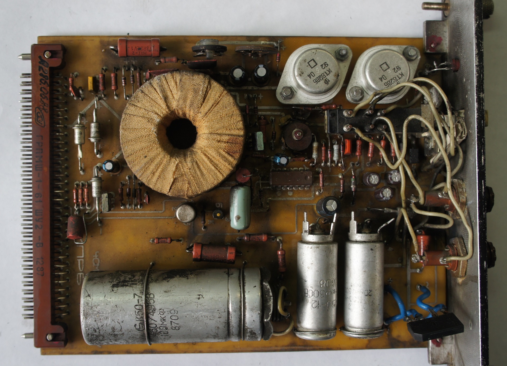
Primary converter. 150V 15-25kHz

Stabilizer + 5V
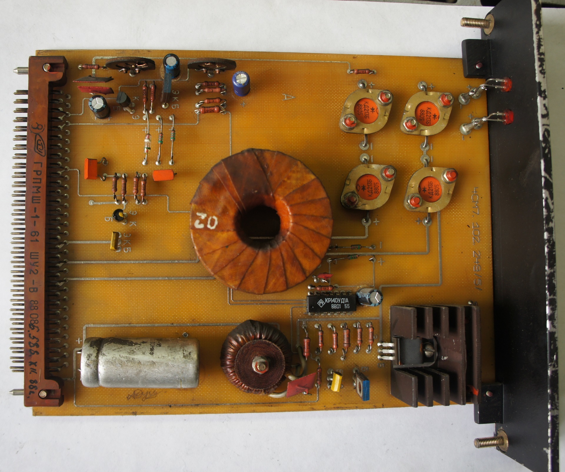
Stabilizer + 12V and -5V
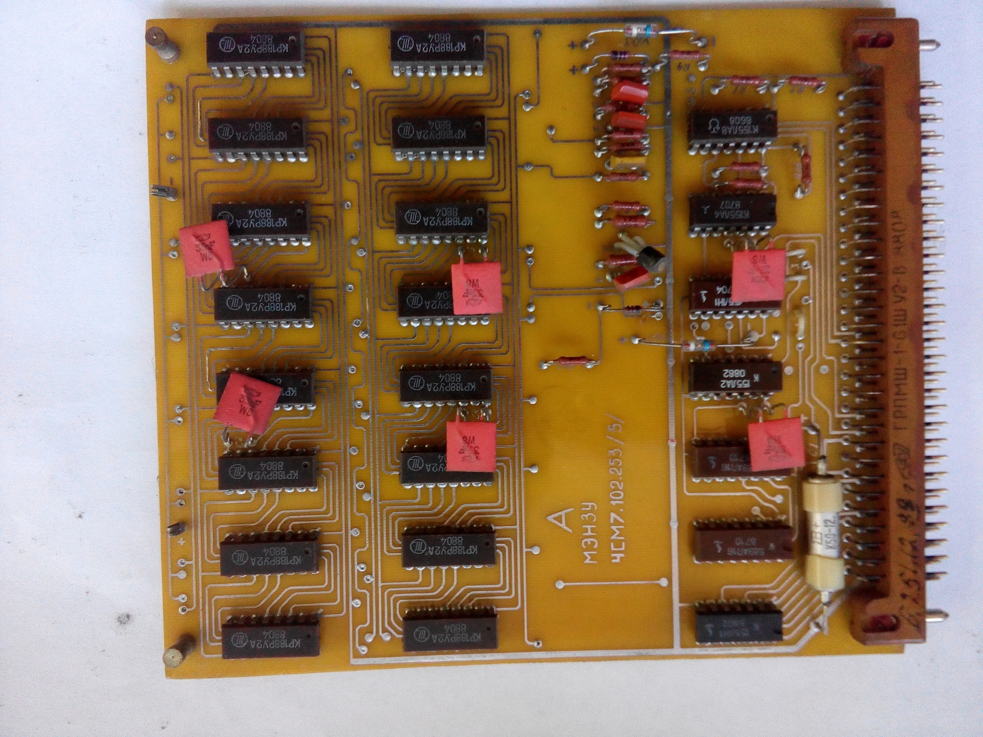
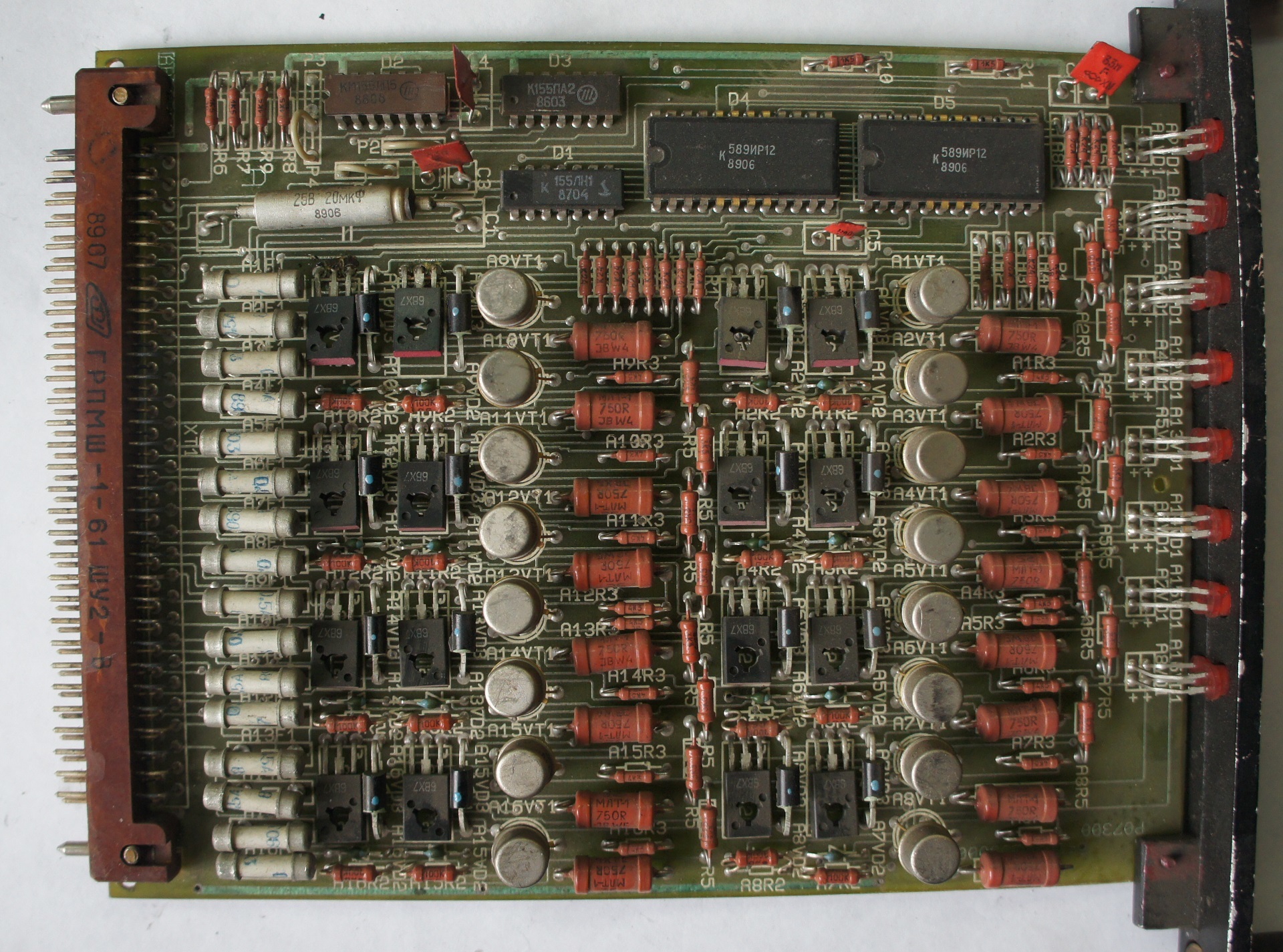
The module of discrete inputs. 16 * 24V
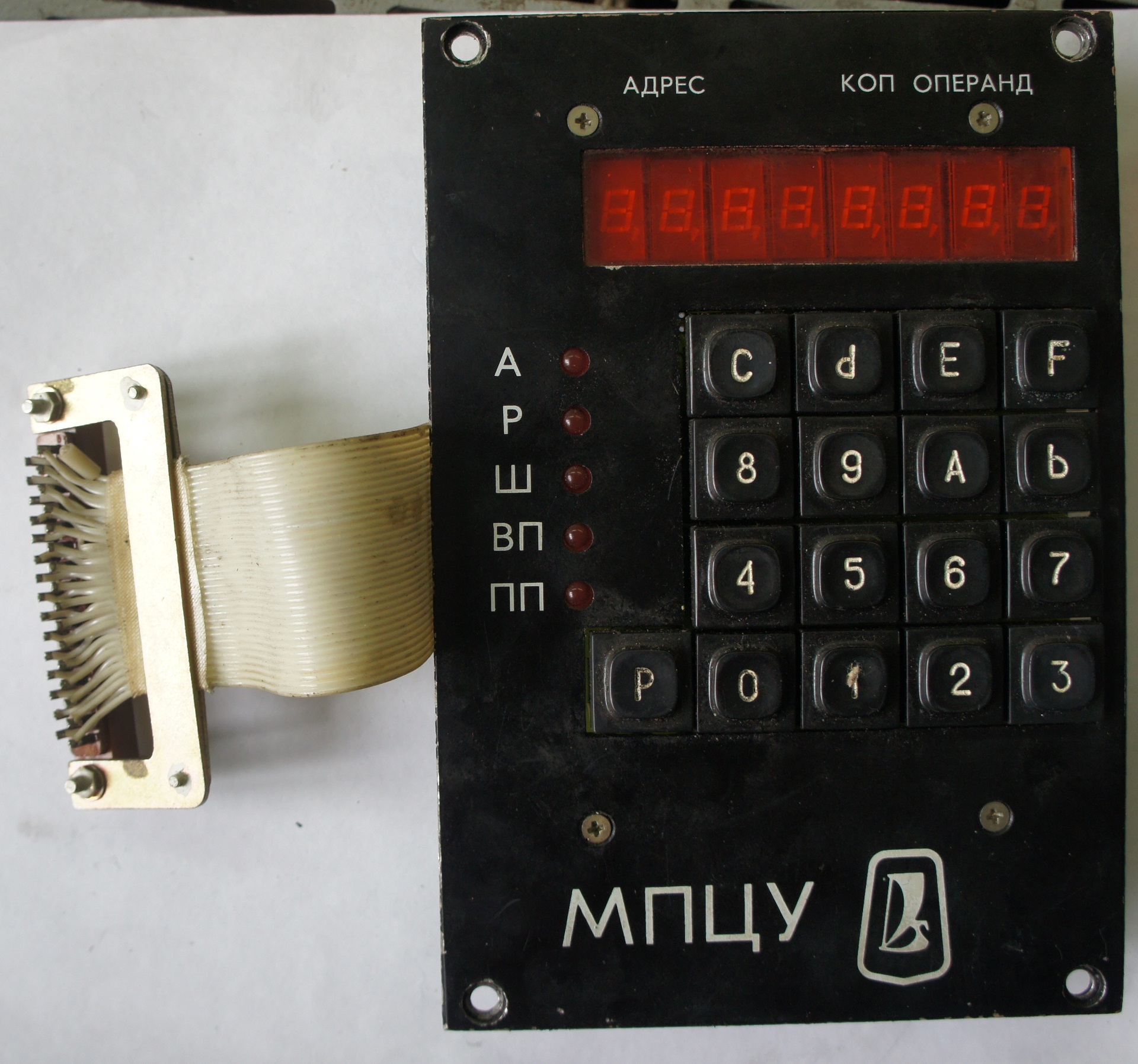
Control module
Control board
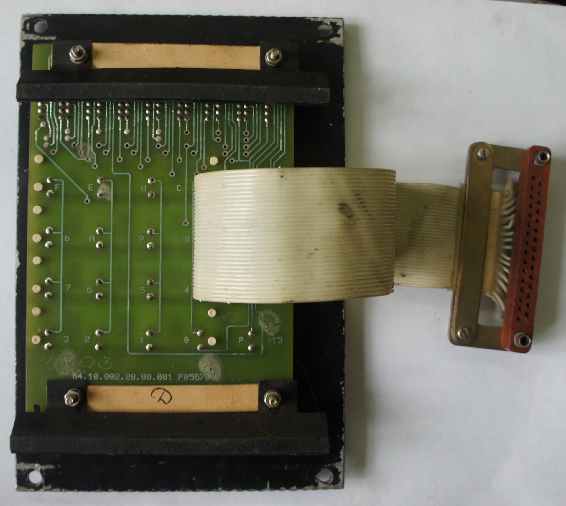
Control board
Custom RAM Battery Pack
UPD 05/11/2017

Another version of the user RAM module. KR537RU10, 2kb.
On the advice of Alexeyslav, I soldered the pad and replaced the microcircuit with a 573RF2 ROM, the contents were read, but there are questions about the structure of the working program in memory in memory, while slowly I understand.


Modified the memory module (service ROM and RAM), replacing the 573RF1 chips, which have three-level power (+ 5V, -5V, + 12V) and 12V address line (!), Because of which the modern available programmers do not know how to work with them, more friendly RF2 \ RF5 \ i2716, but even had to blink with them - minipro 866 did not want to flash them correctly, decided to raise the programming voltage by connecting two AA batteries to the Vprogr line break.
It was possible to read the contents of RF1 by collecting the programmer on the arduino mega according to the description from the Denis ParyshevD article Express Specialist , for which he thanks a lot .
I put the dumps.
→ ROM dumps separately and combined for mcx 573RF2
→ Technical description and operating instructions
General form.
I work as an electronics engineer in the wreckage of a once-large factory for the production of valves and pushers, whose machine park is a wild technology vinaigret from the 60s of the last century to the present day. Such a rarity still works on a pair of machines, it is built on the basis of a kr580 processor, up to 2 kb of user RAM on KR188RU2A, 256 bytes of service RAM, up to 48 discrete inputs / outputs (24v, 0.5a). Entering the work program is possible through the remote control on the MPCU itself, or through a PC via RS-232 interface. Safety of the entered program at power off is provided by 3 \ 6 AA elements. Small mentions in the network of this device are mainly related to using it as a controller of an industrial robot, this was also at our factory, but, like many other equipment, went to scrap. When debugging the machine is very useful and convenient ability to manually enable a particular port. The command system is sharpened by the implementation of the flowchart, which is also very convenient for simple programs.
')
A detailed description of the work in the documentation allowed my predecessors to remake the memory module into the programmer of ROM RF1 \ RF2 with processing programs, as well as create a “Frankenstein” - only 4 blocks remained in the frame - processor, memories with modified ROM, with a wired user program, input modules and output. Power +5 \ +12 \ -5 served from an external source, the start command is automatically given when turned on using a capacitor with a resistor, plugged in instead of the control panel, the user RAM block is missing.))
With the exception of BP, failing due to drying capacitors, the device is quite reliable and trouble-free.
In the near future I will try to upload the dumps of the ROM.
Processor module
Memory module - ROM and service RAM
User RAM Module, 512B
Output module 16 * 24V * 0.5A
Primary converter. 150V 15-25kHz
Stabilizer + 5V
Stabilizer + 12V and -5V
The module of discrete inputs. 16 * 24V
Control module
Control board
Control board
Custom RAM Battery Pack
UPD 05/11/2017
Another version of the user RAM module. KR537RU10, 2kb.
On the advice of Alexeyslav, I soldered the pad and replaced the microcircuit with a 573RF2 ROM, the contents were read, but there are questions about the structure of the working program in memory in memory, while slowly I understand.
Modified the memory module (service ROM and RAM), replacing the 573RF1 chips, which have three-level power (+ 5V, -5V, + 12V) and 12V address line (!), Because of which the modern available programmers do not know how to work with them, more friendly RF2 \ RF5 \ i2716, but even had to blink with them - minipro 866 did not want to flash them correctly, decided to raise the programming voltage by connecting two AA batteries to the Vprogr line break.
It was possible to read the contents of RF1 by collecting the programmer on the arduino mega according to the description from the Denis ParyshevD article Express Specialist , for which he thanks a lot .
I put the dumps.
→ ROM dumps separately and combined for mcx 573RF2
→ Technical description and operating instructions
Source: https://habr.com/ru/post/402929/
All Articles