Completion of the Chinese ST-Link v2: add the SWO debug information output interface and foot reset
 Hi, Geektimes!
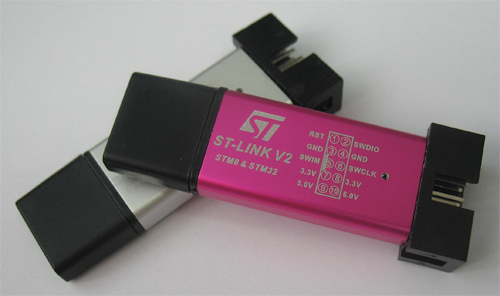
Today I want to tell you about the finalization of the Chinese soldering iron ST-Link v2. You can add SWO output to it to get debug information and a Reset control foot for STM32 microcontrollers (that foot Reset, which is already there, for STM8). Perhaps for many this is not a discovery, but let there be information for beginners. Who cares, I ask under the cat.
Why is it necessary?
The SWD interface used for debugging STM32 microcontrollers supports transferring debug information through SWO output in real time, which is very convenient. Well, the Reset foot is needed so that you can comfortably flash the controller in case the SWD interface is disabled. The reason of course is far-fetched, because for the firmware you can always press the Reset button with handles, but let it be. For example, at the dawn of my acquaintance with STM32, I received a debug board from China with an LED blinking demo program and SWD turned off, I did not immediately understand how to connect to it.
')
Refinement itself
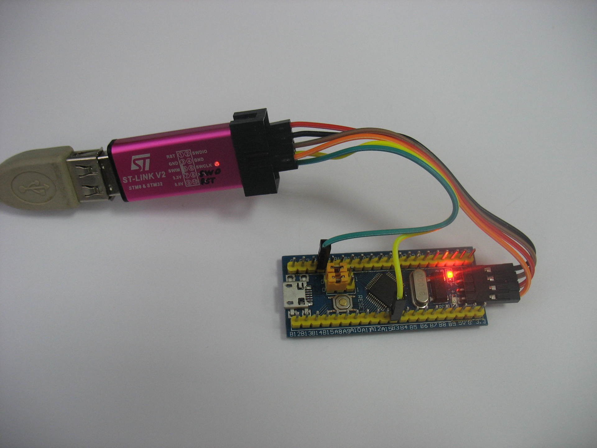
 We will need a scalpel, a soldering iron and a few centimeters of very thin wire; I have this MGTF * some kind of it *. On these programmers, the connector is divided into two parts: the left - for STM8 and the right - for STM32, so the Reset existing there is not suitable for STM32, we will make our own.
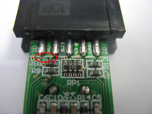
First of all, cut the paths leading to unnecessary pins. At my first modified programmer, I cut off the Reset and SWIM legs, because I did not plan to work with STM8, but now I will use extra pins 3.3 and 5 V (they are duplicated on the connector), so as not to spoil the functionality of the programmer, it will suddenly come in handy.
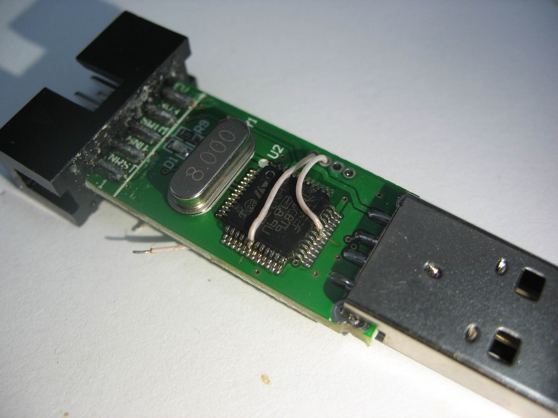
The wires must be soldered to the 18 (Reset) and 31 (SWO) legs of the microcontroller. This is still an occupation, but with a certain skill it can be done. I had wires well entered into the holes on the board, which gave additional fixation. In general, in a good way, you must immediately fix them with glue on the microcontroller. Solder free ends through small resistors (let it be 22 Ohms) to the newly cut pins.
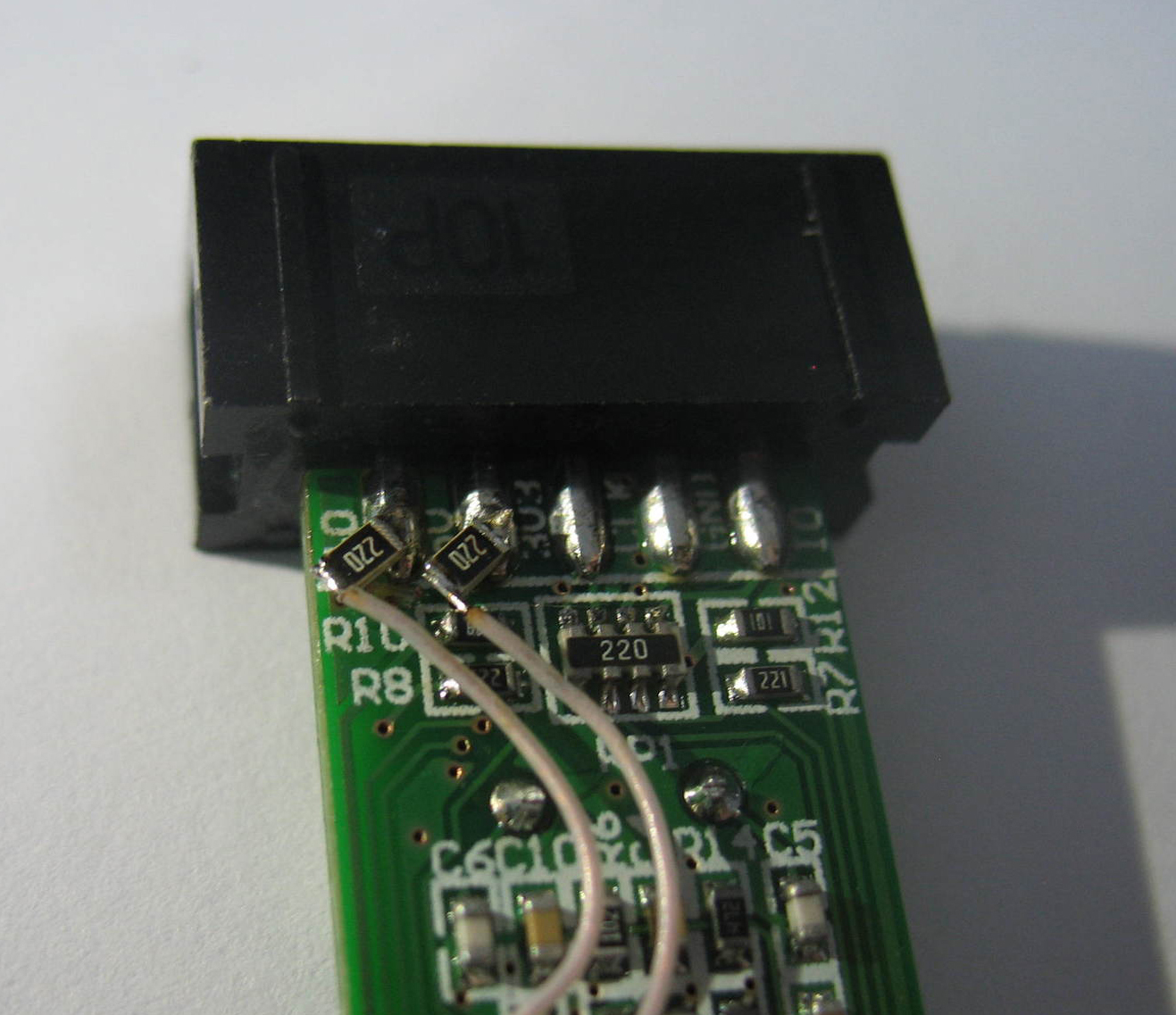
You can close the case and sign new conclusions, so as not to forget where it is.
SWO check
To use SWO you need:
- activate SWD ;
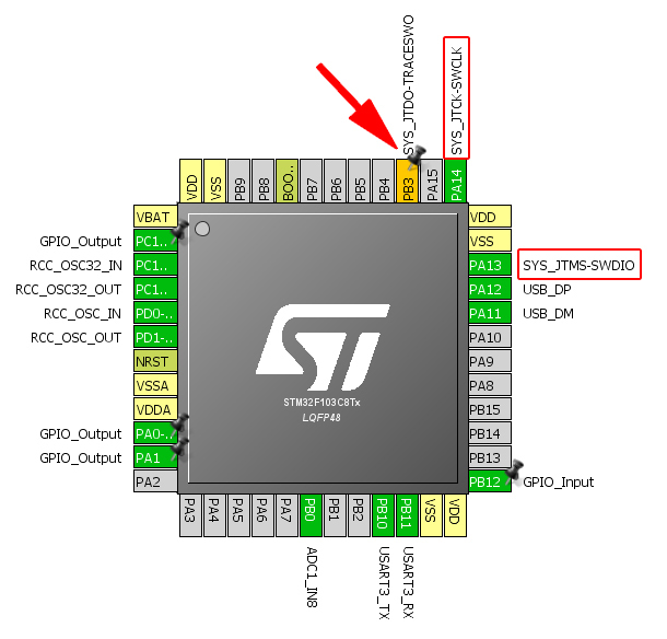
- enable the appropriate output (for STM32F103C microcontrollers this is PB3) on TRACESWO ;
- make sure that SWO is enabled in the programming environment, and not semihosting ;
- connect the library #include “stdio.h” in the program header;
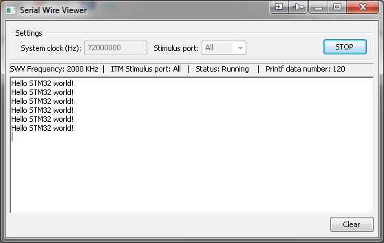
- in the program code use printf (“Hello STM32 world! \ R \ n”) ;
You can view these messages through the terminal in the STM32 ST-LINK Utility program, or directly during debugging in your environment (I use IAR).
Reset check
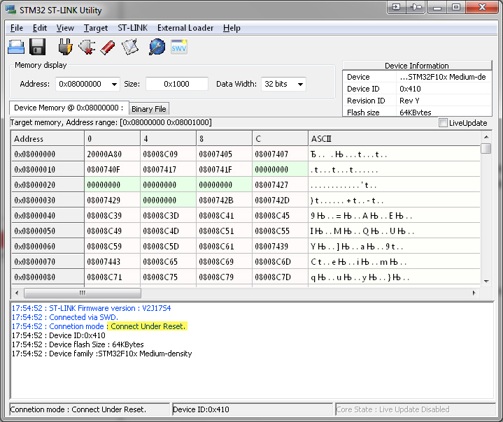
Suppose for some reason SWD is disabled on the microcontroller: either you forgot to enable it during initialization, or a new board came with a wired demo program. Of course, you can sew up by pulling the Reset leg to the ground (usually there is a button on the debug boards), but this is not always convenient. After all, you can simply connect a contact from the programmer and sew in automatic mode.
In the same program STM32 ST-LINK Utility, select "Connect under reset" and connect to the firmware or memory of the microcontroller.
Or, in your IDE, select the appropriate item:

This will allow you to flash and enter the debug mode, but as soon as you reach the initialization of the peripherals, the SWD will be turned off and the connection with the controller will be lost.
Thank you for your attention, I hope someone will come in handy.
Source: https://habr.com/ru/post/402927/
All Articles