Black box smoker
Many people smoke too much, especially when they are addicted to something and do not notice how to smoke one cigarette after another. The smoker’s black box does not allow the next cigarette to be taken until a certain period of time has passed. In this article I will pay attention to some details that may be useful for other developments, especially for the not very famous Teensy LC controller (Arduino family).
Mechanics
Parts of a CIAK are printed on a 3D printer and, after assembly of the bottom, middle and top parts, are glued together.
')

The locking mechanism is made electromechanical, while the main locking functions are implemented purely mechanically, this makes it difficult to break into the CRL by manipulating gaps and removing the batteries.
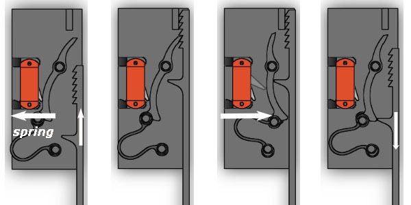
The locking system consists of a rack with teeth and a bistable ratchet, which allows the tray to move only in the direction of closure. Upon reaching a predetermined period of time, the servo makes a single movement back and forth and pushes the ratchet, which is set to the second stable state "open". The CRL remains open until the user mechanically pulls out the tray. When extending the tray pushes the ratchet and translates it into a cocked state again.
The loader is made in the form of a drum with 4 cavities for cigarettes. To avoid trying to get a cigarette through the loader, the ratchet mechanism does not allow movement in the opposite direction, from which side the bump stops are made.

Cuts are made on the top cover, they allow you to eliminate possible distortions of cigarettes inside the box and shake out the tobacco chips.
Interface
To control the time, the number of cigarettes in the cell, and the number of cigarettes removed, the OLED display is monitored. It is turned off almost all the time so as not to discharge the battery and is turned on only by a signal from the central capacitive sensor, which is triggered when the hand is brought to the CAM or the signal from the button when the cigarettes are loaded. Another button captures the moment of closing the tray and starts the next delay cycle. Two additional capacitive sensors are located on the rear wall and serve to adjust the counters of cigarettes (necessary, for example, when changing batteries).
Electronics
The microcontroller is the Teensy LC. This arduin-like device, compatible with most Arduin libraries, was chosen because it has support for capacitive sensors (touch sense interface (TSI)). The sensors are so sensitive that they can easily feel the raised hand at a distance of a centimeter. Teensy LC has a so-called LLWU mode; in this mode, all modules are in sleep mode, with the exception of the 1-kHz oscillator. You can exit this sleep mode in 4 ways a) receive an interrupt from a capacitive sensor, b) receive an interrupt from a pin, c) receive an overflow 1-kHz counter (low-power timer, LPTMR), d) receive an interrupt from alarm.
That's where the author expected the trouble: the original plans were to use TSI to wake up from the sleeping state when giving a hand, and LPTMR for periodic interruptions to adjust the TSI levels (depending on environmental conditions) and control over time. But it turned out that LPTMR is used for the operation of TSI, and, accordingly, cannot be used as a time counter. (LPTMR overflow interrupt is a hardware triggering for TSI, and, of course, must be fast to monitor the sensor. Usually this counter is preset to minus one so that TSI is polled as often as possible at 1 kHz).
Another possibility would be to use the RTC alarm interrupt, but the fact is that the Tenncy LC does not have real time clock (RTC). Rather, the RTC is in the processor itself, but there is no layout for the RTC quartz on the board. However, the processor developer left some loophole for inquiring minds. The 1kHz oscillator (which is in sleep mode) can be used as a source for the RTC control registers. Then it turns out that the RTC can count not second intervals (as when using quartz at 32 kHz), but 32 second intervals, if you use a 1 kHz oscillator. Of course, this accuracy is not enough. But there is a way out.
Here's how it works:
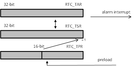
There is an RTC Time Prescaler Register (RTC_TPR). This 16-bit register counts oscillator pulses. If it overflows, RTC Time Seconds Register (RTC_TSR) increases by one. In classic mode, these are the seconds that are compared to the RTC Time Alarm Register (RTC_TAR); if a match occurs, an alarm interrupt is generated. When using the usual 32kHz quartz, RTC_TSR is not preset, but each time it is counted from zero (32768 to overflow (seconds)). But if we each time preset RTC_TSR, given that we have a slow 1kHz oscillator, we can get alarm interrupt up to millisecond accuracy (not taking into account the inaccuracy of the oscillator itself). Of course, RTC_TAR must also be recalculated accordingly.
For example, if we want to set the period to 87 seconds, we must write 2 in RTC_TSR (2 * 32768 = 65536ms = 65.536s), 2 in RTC_TAR, and 32768- (87 * 1000-65536) = 11304 in RTC_TSR. Then before the first overflow of RTC_TPR, 32.768-11.304 = 21.464 seconds will pass, and two full cycles of 2 * 32.768 = 65.536 will be added to them, which will be just 21.464 + 65.536 = 87 seconds
In general, as follows:
And even we can keep track of the total time (up to an error of 1kHz oscillator), for example, if at the beginning of the program all RTC registers were zero:
The accuracy of the 1kHz oscillator is small, but for our purposes it will be enough. It should be noted that when you start a new alarm, we modify the RTC registers, so if you need to keep track of the time, before the alarm is started, they must be remembered, and after exiting the alarm interrupt are recalculated again, taking into account the time spent in hibernation. I described it in detail here: about RTC for Teency LC
In a CRL, an interrupt every 10 minutes measures and memorizes the signal level from capacitive sensors in the absence of a hand. This is done in order to be able to reliably track changes in signals when approaching. With a background of ~ 500 units, we use an elevation level of ~ 20 units, this makes it possible to feel the hand at a distance of 5-10mm. The background level depends on temperature and humidity, so for reliability it should be periodically adjusted. This, I believe, is a flaw in processor developers. Why they did not give the opportunity to simultaneously wake up from TSI and some other low power counter (all we had to add another register), because periodic adjustment of TSI levels is almost mandatory, even if you do not need a timer for other purposes!
Now about the energy consumed. In LLWU sleep mode, the Teensy LC consumes about 15 uA in the absence of a body kit. We had to connect another OLED display and servo. Both of these devices have high leakage currents even in the passive state.
With OLED everything is simple, this is Adafruit 0.96 ”Monochrome 128x64 OLED display, it is powered by 3.3V, consumes a current of the order of 20 mA in the on state (depending on the number of pixels involved) and is controlled by SPI. That is, it is enough to connect its power input to the Teensy LC 20 mA output (Teency has different types of outputs) and is ready. When everyone sleeps, this output is simply transferred to the 3rd state and the current does not flow through the display. When you wake up, the output translates to output high state and becomes Vcc for the display.
Servo is a bit more complicated. Servo in standby mode consumes a current of about 2 mA, which, of course, is not acceptable. Therefore, it is necessary to turn it off completely at bedtime. Unlike classical Arduin, Teensy LC has a rather small choice of power supply: it is either 1.7-3.3 V directly included, or 2.6-5.5 V (with internal voltage regulator turned on). Usually available servos work at least from 1S Lipo, and this is 3.3-4.2 V. Therefore, we need to include three standard batteries in series in order to have from 3.3 (discharge) to 4.6 V (new). For most servo 3.3 V at the operating limit, therefore, direct Teensy outputs cannot be used (as for OLED). And the current during rotation is about 50 mA, which is a bit too much for Teensy LC. Therefore, the servo is enabled via MOSFET:

With this inclusion it may seem that it is not safe as with the MOSFET turned off the voltage at the PWM ctrl input exceeds 3.3 V, and the inputs of the Tennsy LC are not 5V tolerant (unlike the classic Arduin). But you should not be afraid of this, remembering that the PWM ctrl current is very small, and there is no need to fear for the limiting diode at the processor input (the reason for the inadmissibility of exceeding Vcc + 0.5 in this diode), moreover, at currents comparable to the current of the closed diode it will not even be open.
in the CWC, I use the HK282 with a 3.3V threshold (just because I had it). Any kind of lower-voltage and low-power servo, it can be possible to be powered directly from the Teensy outputs, according to the scheme used for OLED.
As a result, the current in sleep mode turned out to be about 50 uA, probably, it could still be reduced, but I decided that this was enough (if it sleeps, the batteries should last for more than 4 years: 2000 mAh / 0.05 mA).
Technical
Printed on Monoprice Ultimate 3D printer, PLA plastic, 0.4 mm nozzle, layer 0.2 mm. For parts of the locking mechanism layer 0.1 mm for accuracy. Springs are also printed on a 3D printer. Print long. For example, the average most large part (it has many internal parts and double walls for electronics and wires) was printed for 20 hours. Glued with cyanacrylate glue. If something breaks inside, you cannot disassemble (protection from maniac smokers), you will have to break it up like a piggy bank and print it again (argument in favor of 3D printers). Drawings and animations are made in SolidWorks, AtmelStudio development environment (yes, AVR (teency) is supported right out of the box, like arduino, via VisualMicro).
Mechanics
Parts of a CIAK are printed on a 3D printer and, after assembly of the bottom, middle and top parts, are glued together.
')
The locking mechanism is made electromechanical, while the main locking functions are implemented purely mechanically, this makes it difficult to break into the CRL by manipulating gaps and removing the batteries.
The locking system consists of a rack with teeth and a bistable ratchet, which allows the tray to move only in the direction of closure. Upon reaching a predetermined period of time, the servo makes a single movement back and forth and pushes the ratchet, which is set to the second stable state "open". The CRL remains open until the user mechanically pulls out the tray. When extending the tray pushes the ratchet and translates it into a cocked state again.
The loader is made in the form of a drum with 4 cavities for cigarettes. To avoid trying to get a cigarette through the loader, the ratchet mechanism does not allow movement in the opposite direction, from which side the bump stops are made.
Cuts are made on the top cover, they allow you to eliminate possible distortions of cigarettes inside the box and shake out the tobacco chips.
Interface
To control the time, the number of cigarettes in the cell, and the number of cigarettes removed, the OLED display is monitored. It is turned off almost all the time so as not to discharge the battery and is turned on only by a signal from the central capacitive sensor, which is triggered when the hand is brought to the CAM or the signal from the button when the cigarettes are loaded. Another button captures the moment of closing the tray and starts the next delay cycle. Two additional capacitive sensors are located on the rear wall and serve to adjust the counters of cigarettes (necessary, for example, when changing batteries).
Electronics
The microcontroller is the Teensy LC. This arduin-like device, compatible with most Arduin libraries, was chosen because it has support for capacitive sensors (touch sense interface (TSI)). The sensors are so sensitive that they can easily feel the raised hand at a distance of a centimeter. Teensy LC has a so-called LLWU mode; in this mode, all modules are in sleep mode, with the exception of the 1-kHz oscillator. You can exit this sleep mode in 4 ways a) receive an interrupt from a capacitive sensor, b) receive an interrupt from a pin, c) receive an overflow 1-kHz counter (low-power timer, LPTMR), d) receive an interrupt from alarm.
That's where the author expected the trouble: the original plans were to use TSI to wake up from the sleeping state when giving a hand, and LPTMR for periodic interruptions to adjust the TSI levels (depending on environmental conditions) and control over time. But it turned out that LPTMR is used for the operation of TSI, and, accordingly, cannot be used as a time counter. (LPTMR overflow interrupt is a hardware triggering for TSI, and, of course, must be fast to monitor the sensor. Usually this counter is preset to minus one so that TSI is polled as often as possible at 1 kHz).
Another possibility would be to use the RTC alarm interrupt, but the fact is that the Tenncy LC does not have real time clock (RTC). Rather, the RTC is in the processor itself, but there is no layout for the RTC quartz on the board. However, the processor developer left some loophole for inquiring minds. The 1kHz oscillator (which is in sleep mode) can be used as a source for the RTC control registers. Then it turns out that the RTC can count not second intervals (as when using quartz at 32 kHz), but 32 second intervals, if you use a 1 kHz oscillator. Of course, this accuracy is not enough. But there is a way out.
Here's how it works:
There is an RTC Time Prescaler Register (RTC_TPR). This 16-bit register counts oscillator pulses. If it overflows, RTC Time Seconds Register (RTC_TSR) increases by one. In classic mode, these are the seconds that are compared to the RTC Time Alarm Register (RTC_TAR); if a match occurs, an alarm interrupt is generated. When using the usual 32kHz quartz, RTC_TSR is not preset, but each time it is counted from zero (32768 to overflow (seconds)). But if we each time preset RTC_TSR, given that we have a slow 1kHz oscillator, we can get alarm interrupt up to millisecond accuracy (not taking into account the inaccuracy of the oscillator itself). Of course, RTC_TAR must also be recalculated accordingly.
For example, if we want to set the period to 87 seconds, we must write 2 in RTC_TSR (2 * 32768 = 65536ms = 65.536s), 2 in RTC_TAR, and 32768- (87 * 1000-65536) = 11304 in RTC_TSR. Then before the first overflow of RTC_TPR, 32.768-11.304 = 21.464 seconds will pass, and two full cycles of 2 * 32.768 = 65.536 will be added to them, which will be just 21.464 + 65.536 = 87 seconds
In general, as follows:
void setAlarm(uint32_t seconds ) { RTC_SR = 0; //disable RTC RTC_TPR=32768-(seconds*1000%32768); RTC_TSR=0; //RTC counter RTC_SR = RTC_SR_TCE; //enable RTC RTC_TAR = seconds*1000/32768; } And even we can keep track of the total time (up to an error of 1kHz oscillator), for example, if at the beginning of the program all RTC registers were zero:
timeEllapsed=(RTC_TSR*32768+RTC_TPR)/1000 The accuracy of the 1kHz oscillator is small, but for our purposes it will be enough. It should be noted that when you start a new alarm, we modify the RTC registers, so if you need to keep track of the time, before the alarm is started, they must be remembered, and after exiting the alarm interrupt are recalculated again, taking into account the time spent in hibernation. I described it in detail here: about RTC for Teency LC
In a CRL, an interrupt every 10 minutes measures and memorizes the signal level from capacitive sensors in the absence of a hand. This is done in order to be able to reliably track changes in signals when approaching. With a background of ~ 500 units, we use an elevation level of ~ 20 units, this makes it possible to feel the hand at a distance of 5-10mm. The background level depends on temperature and humidity, so for reliability it should be periodically adjusted. This, I believe, is a flaw in processor developers. Why they did not give the opportunity to simultaneously wake up from TSI and some other low power counter (all we had to add another register), because periodic adjustment of TSI levels is almost mandatory, even if you do not need a timer for other purposes!
Now about the energy consumed. In LLWU sleep mode, the Teensy LC consumes about 15 uA in the absence of a body kit. We had to connect another OLED display and servo. Both of these devices have high leakage currents even in the passive state.
With OLED everything is simple, this is Adafruit 0.96 ”Monochrome 128x64 OLED display, it is powered by 3.3V, consumes a current of the order of 20 mA in the on state (depending on the number of pixels involved) and is controlled by SPI. That is, it is enough to connect its power input to the Teensy LC 20 mA output (Teency has different types of outputs) and is ready. When everyone sleeps, this output is simply transferred to the 3rd state and the current does not flow through the display. When you wake up, the output translates to output high state and becomes Vcc for the display.
Servo is a bit more complicated. Servo in standby mode consumes a current of about 2 mA, which, of course, is not acceptable. Therefore, it is necessary to turn it off completely at bedtime. Unlike classical Arduin, Teensy LC has a rather small choice of power supply: it is either 1.7-3.3 V directly included, or 2.6-5.5 V (with internal voltage regulator turned on). Usually available servos work at least from 1S Lipo, and this is 3.3-4.2 V. Therefore, we need to include three standard batteries in series in order to have from 3.3 (discharge) to 4.6 V (new). For most servo 3.3 V at the operating limit, therefore, direct Teensy outputs cannot be used (as for OLED). And the current during rotation is about 50 mA, which is a bit too much for Teensy LC. Therefore, the servo is enabled via MOSFET:
With this inclusion it may seem that it is not safe as with the MOSFET turned off the voltage at the PWM ctrl input exceeds 3.3 V, and the inputs of the Tennsy LC are not 5V tolerant (unlike the classic Arduin). But you should not be afraid of this, remembering that the PWM ctrl current is very small, and there is no need to fear for the limiting diode at the processor input (the reason for the inadmissibility of exceeding Vcc + 0.5 in this diode), moreover, at currents comparable to the current of the closed diode it will not even be open.
in the CWC, I use the HK282 with a 3.3V threshold (just because I had it). Any kind of lower-voltage and low-power servo, it can be possible to be powered directly from the Teensy outputs, according to the scheme used for OLED.
As a result, the current in sleep mode turned out to be about 50 uA, probably, it could still be reduced, but I decided that this was enough (if it sleeps, the batteries should last for more than 4 years: 2000 mAh / 0.05 mA).
Technical
Printed on Monoprice Ultimate 3D printer, PLA plastic, 0.4 mm nozzle, layer 0.2 mm. For parts of the locking mechanism layer 0.1 mm for accuracy. Springs are also printed on a 3D printer. Print long. For example, the average most large part (it has many internal parts and double walls for electronics and wires) was printed for 20 hours. Glued with cyanacrylate glue. If something breaks inside, you cannot disassemble (protection from maniac smokers), you will have to break it up like a piggy bank and print it again (argument in favor of 3D printers). Drawings and animations are made in SolidWorks, AtmelStudio development environment (yes, AVR (teency) is supported right out of the box, like arduino, via VisualMicro).
Source: https://habr.com/ru/post/402867/
All Articles