Thermoacoustic engine - Stirling engine without pistons
Stirling engine - engine with external heat supply. External heat supply is very convenient when there is a need to use non-organic fuels as a heat source. For example, you can use solar energy, geothermal energy, waste heat from various enterprises.
A nice feature of the Stirling cycle is that its efficiency equals the efficiency of the Carnot cycle [1]. Naturally, real Stirling engines have lower efficiency and often much more. The Stirling engine began its existence with a device that has many moving parts, such as pistons, connecting rods, crankshaft, bearings [2]. In addition, the generator rotor also spun (Figure 1).
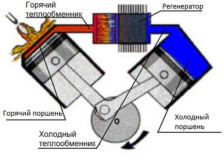
Figure 1 - Stirling Alpha Type Engine
Look at the Stirling Alpha type engine. When the shaft rotates, the pistons start to move the gas from cold to hot cylinder, or vice versa, from hot to cold. But they do not just overtake, but also squeeze and expand. A thermodynamic cycle takes place. You can mentally imagine in the picture that when the shaft turns in such a way that the axis on which the connecting rods are mounted will be at the top, this will be the moment of greatest compression of the gas, and when at the bottom, then the expansion. True, this is not entirely true due to the thermal expansion and contraction of gas, but approximately all of it is still so.
')
The heart of the engine is the so-called core, which consists of two heat exchangers - hot and cold and between them there is a regenerator. Heat exchangers are usually made of lamellar, and the regenerator is most often a stack assembled from a metal mesh. Why do we need heat exchangers is clear - to heat and cool the gas, and why do we need a regenerator? And the regenerator is a real heat accumulator. When the hot gas moves to the cold side, it heats the regenerator and the regenerator stores thermal energy. When the gas moves from the cold to the hot side, the cold gas is heated in the regenerator and thus this heat, which without a regenerator would be irretrievably spent on heating the environment, is saved. So, the regenerator is a very necessary thing. A good regenerator increases the efficiency of the engine by about 3.6 times.
To fans who dream of building a similar engine on their own, I want to tell you more about heat exchangers. Most of the self-made Stirling engines, from those that I saw, do not have heat exchangers at all (I'm talking about alpha-type engines). The heat exchangers are the pistons and cylinders themselves. One cylinder heats up, the other cools. The area of the heat exchange surface in contact with the gas is very small. So, it is possible to significantly increase the engine power by putting heat exchangers at the cylinder inlet. And even in Figure 1, the flame is directed straight to the cylinder, which is not quite the case with factory engines.
Let's return to the history of the development of Stirling engines. So, let the engine is good in many ways, but the presence of oil rings and bearings reduced the life of the engine and engineers thought hard how to improve it and came up with it.
In 1969, William Bale investigated the resonance effects in the engine and later was able to make an engine for which neither the connecting rods nor the crankshaft are needed. Piston synchronization occurred due to resonance effects. This type of engine became known as a free piston engine (Figure 2).
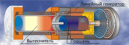
Figure 2 - Stirling Free Piston Engine
Figure 2 shows a free piston beta type engine. Here, the gas passes from the hot to the cold area, and vice versa, thanks to the displacer (which moves freely), and the working piston does useful work. The displacer and the piston oscillate on the spiral springs, which can be seen on the right side of the figure. The difficulty is that their oscillations must be with the same frequency and with a phase difference of 90 degrees, and all this is due to the resonance effects. Make it pretty hard.
Thus, the number of parts was reduced, but the requirements for accuracy of calculations and manufacturing were tightened. But the reliability of the engine has undoubtedly increased, especially in structures where flexible membranes are used as a displacer and a piston. In this case, there are no friction parts in the engine at all. Electricity, if desired, with such an engine can be removed using a linear generator.
But even this was not enough for the engineers, and they began to look for ways to get rid of not just moving parts, but generally moving parts. And they found such a way.
In the seventies of the 20th century, Peter Tseperli realized that the sinusoidal oscillations of pressure and gas velocity in a Stirling engine, and the fact that these oscillations are in phase, very much resemble pressure oscillations and gas velocities in a traveling sound wave (Fig. 3 ).
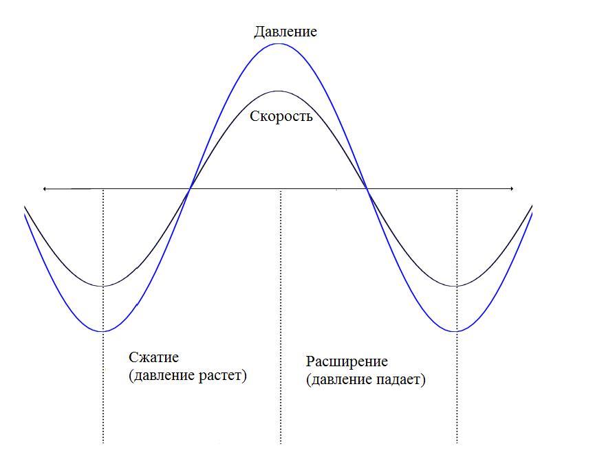
Figure 3 - Graph of pressure and speed of traveling acoustic wave as a function of time. It is shown that pressure and velocity fluctuations are in phase.
This idea came not accidentally Taperli, because before him there was a lot of research in the field of thermoacoustics, for example, Lord Rayleigh himself in 1884 qualitatively described this phenomenon.
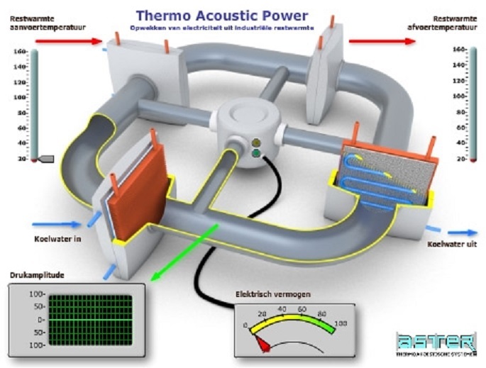
Thus, he proposed to completely abandon the pistons and propellants, and use only the acoustic wave to control pressure and gas movement. This results in an engine without moving parts and theoretically capable of achieving the efficiency of the Stirling cycle, and hence Carnot. In reality, the best performance is 40-50% of the efficiency of the Carnot cycle (Figure 4).
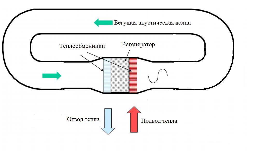
Figure 4 - Diagram of a traveling wave thermoacoustic engine
It can be seen that the traveling-wave thermo-acoustic engine is exactly the same core, consisting of heat exchangers and a regenerator, only instead of pistons and connecting rods there is simply a looped pipe, which is called a resonator. But how does this engine work if there are no moving parts in it? How is this possible?
To begin, let's answer the question, where does the sound come from? And the answer is that it appears by itself when a sufficient temperature difference between two heat exchangers occurs. The temperature gradient in the regenerator allows you to amplify sound vibrations, but only a certain wavelength equal to the length of the resonator. From the very beginning, the process looks like this: when a hot heat exchanger is heated, micro rustles occur, perhaps even crackles from thermal deformation, this is inevitable. These rustles are noise, having a wide range of frequencies. From all this rich spectrum of sound frequencies, the engine begins to amplify that sound wave, the wavelength of which is equal to the length of the pipe - the resonator. And no matter how small the initial oscillation, it will be strengthened to the maximum possible value. The maximum sound volume inside the engine occurs when the sound amplification power using heat exchangers is equal to the power loss, i.e. the sound attenuation power. And this maximum value sometimes reaches huge values of 160 dB. So inside this engine is really loud. Fortunately, the sound cannot reach the outside, as the resonator is hermetic and therefore, standing next to the engine running, it is barely audible.
The amplification of a certain frequency of sound occurs due to all the same thermodynamic cycle - the Stirling cycle, which is carried out in the regenerator.
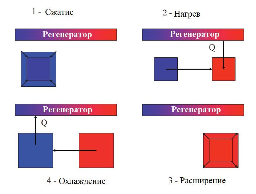
Figure 5 - Cycle stages are rough and simplistic.
As I already wrote, in a thermoacoustic engine there are no moving parts at all, it generates only an acoustic wave inside of itself, but, unfortunately, without moving parts it is impossible to remove electric power from the engine.
Usually extract energy from thermo-acoustic engines with the help of linear generators. The elastic membrane oscillates under the pressure of a high-intensity sound wave. Inside the copper core coil, magnets attached to the membrane vibrate. Electricity is produced.
In 2014, Kees de Blok, Pawel Owczarek and Maurice Francois from Aster Thermoacoustics showed that a bi-directional pulsed turbine connected to a generator is suitable for converting sound wave energy into electricity [3].
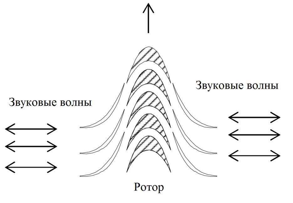
Figure 6 - Pulse Turbine Scheme
The impulse turbine rotates in the same direction, regardless of the direction of flow. Figure 6 shows schematically the stator blades on the sides and the rotor blades in the middle.
And so the turbine looks like in reality:
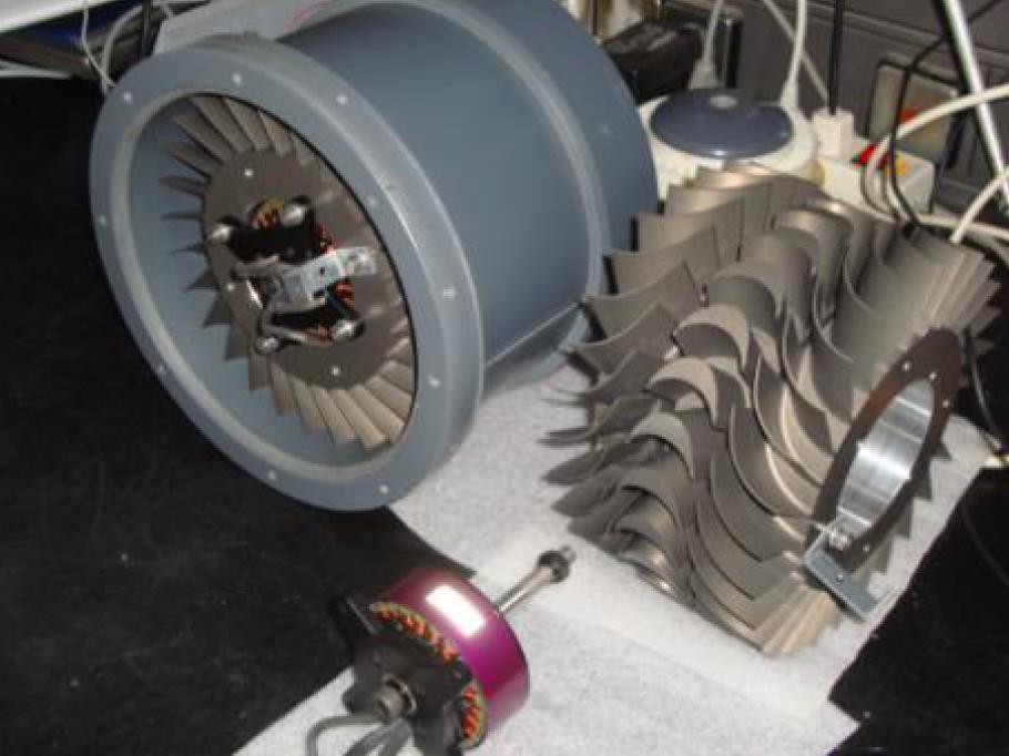
Figure 7 - Appearance of a bidirectional pulsed turbine
It is expected that the use of a turbine instead of a linear generator will greatly reduce the cost of construction and will increase the power of the device up to the typical power of CHP, which is impossible with linear generators.
Well, we will continue to closely monitor the development of thermo-acoustic engines.
List of used sources
[1] M.G. Kruglov. Stirling engines. Moscow "Mechanical Engineering", 1977.
[2] G. Reeder, C. Hooper. Stirling engines. Moscow "Peace", 1986.
[3] Kees de Blok, Pawel Owczarek. Acoustic to electric power conversion, 2014.
A nice feature of the Stirling cycle is that its efficiency equals the efficiency of the Carnot cycle [1]. Naturally, real Stirling engines have lower efficiency and often much more. The Stirling engine began its existence with a device that has many moving parts, such as pistons, connecting rods, crankshaft, bearings [2]. In addition, the generator rotor also spun (Figure 1).
Figure 1 - Stirling Alpha Type Engine
Look at the Stirling Alpha type engine. When the shaft rotates, the pistons start to move the gas from cold to hot cylinder, or vice versa, from hot to cold. But they do not just overtake, but also squeeze and expand. A thermodynamic cycle takes place. You can mentally imagine in the picture that when the shaft turns in such a way that the axis on which the connecting rods are mounted will be at the top, this will be the moment of greatest compression of the gas, and when at the bottom, then the expansion. True, this is not entirely true due to the thermal expansion and contraction of gas, but approximately all of it is still so.
')
The heart of the engine is the so-called core, which consists of two heat exchangers - hot and cold and between them there is a regenerator. Heat exchangers are usually made of lamellar, and the regenerator is most often a stack assembled from a metal mesh. Why do we need heat exchangers is clear - to heat and cool the gas, and why do we need a regenerator? And the regenerator is a real heat accumulator. When the hot gas moves to the cold side, it heats the regenerator and the regenerator stores thermal energy. When the gas moves from the cold to the hot side, the cold gas is heated in the regenerator and thus this heat, which without a regenerator would be irretrievably spent on heating the environment, is saved. So, the regenerator is a very necessary thing. A good regenerator increases the efficiency of the engine by about 3.6 times.
To fans who dream of building a similar engine on their own, I want to tell you more about heat exchangers. Most of the self-made Stirling engines, from those that I saw, do not have heat exchangers at all (I'm talking about alpha-type engines). The heat exchangers are the pistons and cylinders themselves. One cylinder heats up, the other cools. The area of the heat exchange surface in contact with the gas is very small. So, it is possible to significantly increase the engine power by putting heat exchangers at the cylinder inlet. And even in Figure 1, the flame is directed straight to the cylinder, which is not quite the case with factory engines.
Let's return to the history of the development of Stirling engines. So, let the engine is good in many ways, but the presence of oil rings and bearings reduced the life of the engine and engineers thought hard how to improve it and came up with it.
In 1969, William Bale investigated the resonance effects in the engine and later was able to make an engine for which neither the connecting rods nor the crankshaft are needed. Piston synchronization occurred due to resonance effects. This type of engine became known as a free piston engine (Figure 2).
Figure 2 - Stirling Free Piston Engine
Figure 2 shows a free piston beta type engine. Here, the gas passes from the hot to the cold area, and vice versa, thanks to the displacer (which moves freely), and the working piston does useful work. The displacer and the piston oscillate on the spiral springs, which can be seen on the right side of the figure. The difficulty is that their oscillations must be with the same frequency and with a phase difference of 90 degrees, and all this is due to the resonance effects. Make it pretty hard.
Thus, the number of parts was reduced, but the requirements for accuracy of calculations and manufacturing were tightened. But the reliability of the engine has undoubtedly increased, especially in structures where flexible membranes are used as a displacer and a piston. In this case, there are no friction parts in the engine at all. Electricity, if desired, with such an engine can be removed using a linear generator.
But even this was not enough for the engineers, and they began to look for ways to get rid of not just moving parts, but generally moving parts. And they found such a way.
In the seventies of the 20th century, Peter Tseperli realized that the sinusoidal oscillations of pressure and gas velocity in a Stirling engine, and the fact that these oscillations are in phase, very much resemble pressure oscillations and gas velocities in a traveling sound wave (Fig. 3 ).
Figure 3 - Graph of pressure and speed of traveling acoustic wave as a function of time. It is shown that pressure and velocity fluctuations are in phase.
This idea came not accidentally Taperli, because before him there was a lot of research in the field of thermoacoustics, for example, Lord Rayleigh himself in 1884 qualitatively described this phenomenon.
Thus, he proposed to completely abandon the pistons and propellants, and use only the acoustic wave to control pressure and gas movement. This results in an engine without moving parts and theoretically capable of achieving the efficiency of the Stirling cycle, and hence Carnot. In reality, the best performance is 40-50% of the efficiency of the Carnot cycle (Figure 4).
Figure 4 - Diagram of a traveling wave thermoacoustic engine
It can be seen that the traveling-wave thermo-acoustic engine is exactly the same core, consisting of heat exchangers and a regenerator, only instead of pistons and connecting rods there is simply a looped pipe, which is called a resonator. But how does this engine work if there are no moving parts in it? How is this possible?
To begin, let's answer the question, where does the sound come from? And the answer is that it appears by itself when a sufficient temperature difference between two heat exchangers occurs. The temperature gradient in the regenerator allows you to amplify sound vibrations, but only a certain wavelength equal to the length of the resonator. From the very beginning, the process looks like this: when a hot heat exchanger is heated, micro rustles occur, perhaps even crackles from thermal deformation, this is inevitable. These rustles are noise, having a wide range of frequencies. From all this rich spectrum of sound frequencies, the engine begins to amplify that sound wave, the wavelength of which is equal to the length of the pipe - the resonator. And no matter how small the initial oscillation, it will be strengthened to the maximum possible value. The maximum sound volume inside the engine occurs when the sound amplification power using heat exchangers is equal to the power loss, i.e. the sound attenuation power. And this maximum value sometimes reaches huge values of 160 dB. So inside this engine is really loud. Fortunately, the sound cannot reach the outside, as the resonator is hermetic and therefore, standing next to the engine running, it is barely audible.
The amplification of a certain frequency of sound occurs due to all the same thermodynamic cycle - the Stirling cycle, which is carried out in the regenerator.
Figure 5 - Cycle stages are rough and simplistic.
As I already wrote, in a thermoacoustic engine there are no moving parts at all, it generates only an acoustic wave inside of itself, but, unfortunately, without moving parts it is impossible to remove electric power from the engine.
Usually extract energy from thermo-acoustic engines with the help of linear generators. The elastic membrane oscillates under the pressure of a high-intensity sound wave. Inside the copper core coil, magnets attached to the membrane vibrate. Electricity is produced.
In 2014, Kees de Blok, Pawel Owczarek and Maurice Francois from Aster Thermoacoustics showed that a bi-directional pulsed turbine connected to a generator is suitable for converting sound wave energy into electricity [3].
Figure 6 - Pulse Turbine Scheme
The impulse turbine rotates in the same direction, regardless of the direction of flow. Figure 6 shows schematically the stator blades on the sides and the rotor blades in the middle.
And so the turbine looks like in reality:
Figure 7 - Appearance of a bidirectional pulsed turbine
It is expected that the use of a turbine instead of a linear generator will greatly reduce the cost of construction and will increase the power of the device up to the typical power of CHP, which is impossible with linear generators.
Well, we will continue to closely monitor the development of thermo-acoustic engines.
List of used sources
[1] M.G. Kruglov. Stirling engines. Moscow "Mechanical Engineering", 1977.
[2] G. Reeder, C. Hooper. Stirling engines. Moscow "Peace", 1986.
[3] Kees de Blok, Pawel Owczarek. Acoustic to electric power conversion, 2014.
Source: https://habr.com/ru/post/402793/
All Articles