CO2 Lamp (mh-z19)
There have already quite often been told about the mh-z19 sensor and about esp8266, as well as not forgetting to mention the mqtt protocol.
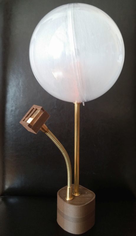
I read all this and decided to combine the read in one device. Actually in the picture this is it.
Entry (skip)
I have been registered on Habré for quite some time and I read it even more, but I am not particularly active, but I must say that I learned a lot of new and useful things here. And I occasionally gnaws at the idea that it is necessary not only to use, but also to give something and share. I cannot offer any particulars, but I completed my project and it seemed to me quite interesting for publication.
Functions / Firmware
The whole project is built on esp8266 and, accordingly, can communicate well with the Internet. For data transfer protocol is used mqtt . Frankly speaking, I didn’t go deep into the protocol device, but the thing turned out to be very convenient, I used the mosca broker for the test at home, and now I’m using cloudmqtt , they have free options, for that little thing.
')
Now you can go to the actual functions.
When I turn on the lamp, it looks if there are already saved settings, if not, it turns on wifi with the name “CO2.box”, at the address “192.168.4.1” it shows the page with the settings:
Screenshot
The lamp itself can operate in two modes:
1. It connects to the mqtt broker, sends data and displays the content of co2 through the LED.
2. Shows only through the LED content of co2 in the room.
LED can change its color from green to red, in theory it is RGB, but I did not connect it to blue, therefore only LED RG. If the co2 content is 400 ppm (PPM Min in webgui), then the lamp shines in pure green and when the concentration increases, the color turns red when the maximum is reached (PPM Max in webgui) starts flashing red.
Reset is displayed on a separate button, also made another button, if you hold it for more than one second, then the settings are reset.
Button code
Button Initialization (GPIO0)
Check how many buttons were pressed and reset
// initialise reset button void BtnInit() { // set GPIO 0 PIN_FUNC_SELECT(PERIPHS_IO_MUX_GPIO0_U, FUNC_GPIO0); // enable pullup resitor PIN_PULLUP_EN(PERIPHS_IO_MUX_GPIO0_U); // disable globar interrupt ETS_GPIO_INTR_DISABLE(); // attach interrupt function ETS_GPIO_INTR_ATTACH(input_intr_handler, NULL); GPIO_DIS_OUTPUT(BTN_CONFIG_GPIO); // empty status GPIO_REG_WRITE(GPIO_STATUS_W1TC_ADDRESS, BIT(2)); // enable interrupt gpio_pin_intr_state_set(GPIO_ID_PIN(BTN_CONFIG_GPIO), GPIO_PIN_INTR_ANYEDGE); // enable global interrupt ETS_GPIO_INTR_ENABLE(); // timer os_timer_disarm(&DebounceTimer); os_timer_setfn(&DebounceTimer, &debounce_timer_cb, 0); } Check how many buttons were pressed and reset
// button reset pressed void ICACHE_FLASH_ATTR debounce_timer_cb(void *arg){ //disable globar interrupt ETS_GPIO_INTR_DISABLE(); gpio_pin_intr_state_set(GPIO_ID_PIN(BTN_CONFIG_GPIO), GPIO_PIN_INTR_ANYEDGE); ETS_GPIO_INTR_ENABLE(); //start if button was pressed any age (hight or low) if(timepressed){ timepressed = 0; uint32 count = system_get_time() - timecount; #ifdef DEBUG os_printf("DIFF: %d us\n", count); #endif //check time between button on/off, if more 1 sec start delete settings in flash if(count >= 1000000){ if(wipe_flash(DELALLCONF) == 0){ os_timer_disarm(&wifiErrorLedTimer); os_timer_disarm(&ppmMaxLed); os_timer_disarm(&SendDataTimer); os_timer_disarm(&wifiConnCheck); os_printf("\n"); startMode(); } } } else { timepressed = 1; timecount = system_get_time(); #ifdef DEBUG os_printf("SYSTEMTIME: %d\n", timecount); #endif } } For mqtt , user authentication via login / pass is supported. You can do the same so that the data is sent via https, but for this you need to sew a certificate into the firmware, which was against the concept - I wanted all settings to be done via webgui.
Problem
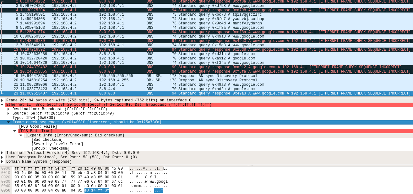
I wanted to run a DNS server on esp8266, so that it would always give its address in response and it was not necessary to enter the IP address. Unfortunately, in my version of esp8266 sdk, I ran into a bug that it incorrectly creates an Ethernet packet and there the checksum does not converge and the response from the client is ignored. I saw the error through wireshark, and also described a similar error on the espressif forum. Therefore, I left a venture.
The firmware turned out to be quite good in general, but for example I didn’t find / understand how to properly close the tcp connection, so when I send data from the browser, it (the browser) is waiting for something and does not close the connection.
In general, the quality of the code, in my opinion, was not very high (or rather, terrible), this is explained by the fact that this is my second project with (the first project was a clock ), as well as the fact that the SDK is not very clear and often the documentation didn't help much and had to look for examples.
For example, I wanted to put a record in the flash in a separate file, but after that the settings stopped being recorded in the flash. I never found why.
Iron side
Then I tried to get off with a minimum set of components, it seemed to work out pretty well. At first I wanted to use esp8266 first version, I found a way on the Internet, how to manage the shift register with just one pin. In Proteus everything worked, but not live. I think my problem was that I did not find suitable capacitors.
esp12e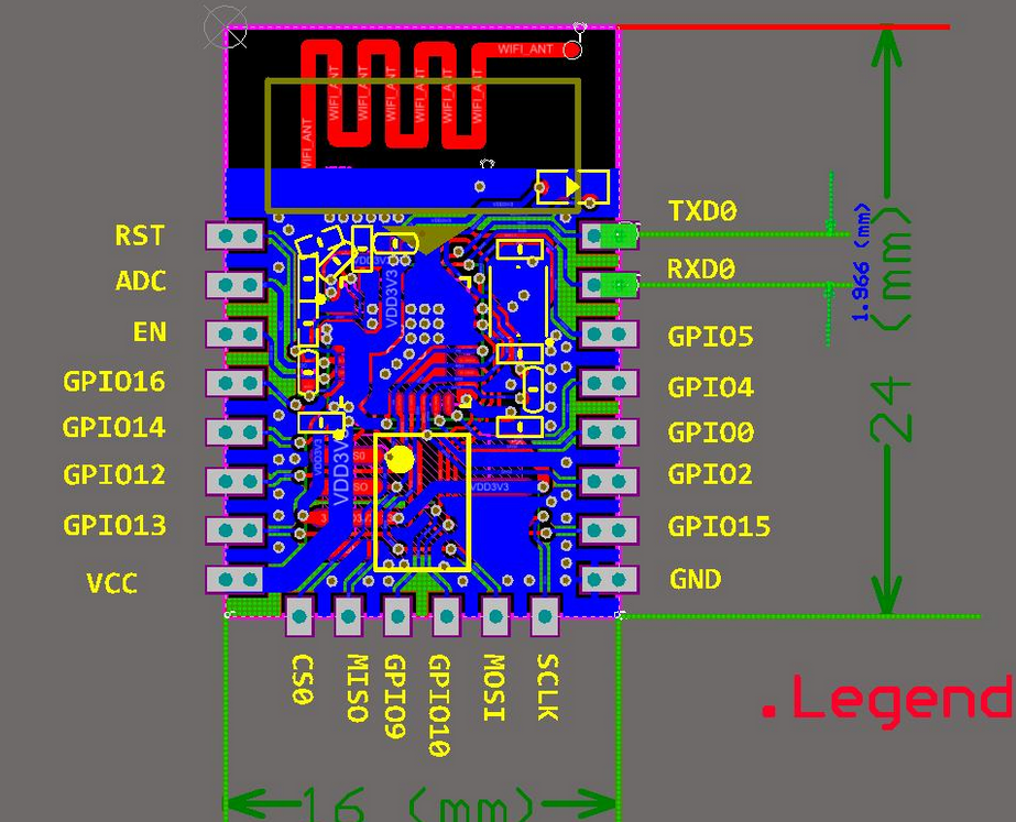
I used ESP8266 12e, as it has 4MB of memory and seven pins that can be used. At the beginning and almost until the end of the project, I wanted to use four additional seven-segment displays that were connected through four shift registers 74hc595 , but later, when I began to dilute the board, it all seemed somewhat cumbersome and redundant to me. In general, I removed them, but in the committees there is still the code where the screen was. Therefore, if anyone needs it, then there you can take the necessary part.
I also wanted all this to work from usb, directly from computer usb or through a power supply unit (like on a phone). I took the power supply from the old Nokia (n900), it produces 1A, so this was enough for the eyes, but I had to lower the voltage for esp8266 to 3.3V.
For this, I used asm1117 and here the first problem was waiting for me, for some reason it gave out only 3c, esp8266 worked for him, but it was not stable and very strange errors appeared at work.
For example, he could not write esp8266 data in a flash, just rebooted, it took me quite a lot of time, until I understood where errors were coming from, I almost did not jump around with a tambourine.
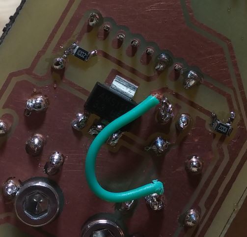
Asm1117 itself gave the required 3.3-3.5v, but on esp8266 there were only 2.8-3.1v. In principle, I didn’t really solve the problem, I suspect that it (the voltage) fell on the wires. Then I redid it as in the picture below and everything began to work stably.
Like now
We also needed 5v only for the co2 sensor, by the way I was able to start it on 3.3v. But there were problems, that he increased his values somewhere per hour running up to 2000ppm, but if he was simply turned off and turned on again, then the values immediately fell.
Scheme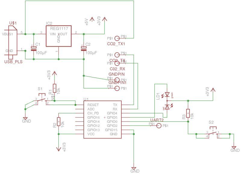
Log output is connected to GPIO2 if something suddenly does not work. Communication with the co2 sensor is standard - through uart.
Well, then it seems like there was nothing particularly difficult. From the scheme that was in the picture above, I made a fee. The experience was already, I had trained on the clock before that and everything was a bit more complicated there. In general, it turned out like this:
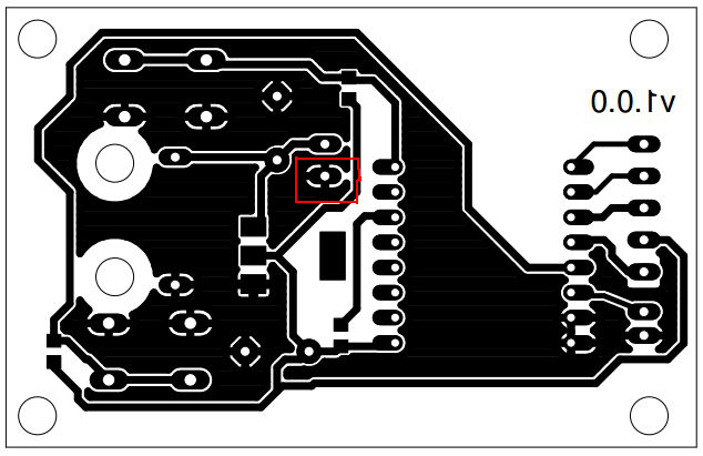
Unfortunately, I have an error here (marked in red), which I noticed only at the end. The ground of the co2 sensor is connected to this pin, but this land is not connected to the rest, and in this form the sensor did not work, I had to attach a bridge in that place.
Lutim, twist, drill, saw
From the picture above you can see that everything was done with loot. I used the method with citric acid, I read about it on the radiokote . They write that the best reaction is obtained.
My set of tools for loot, in fact, in the green box on the right, everything happens.
Everything you need for weed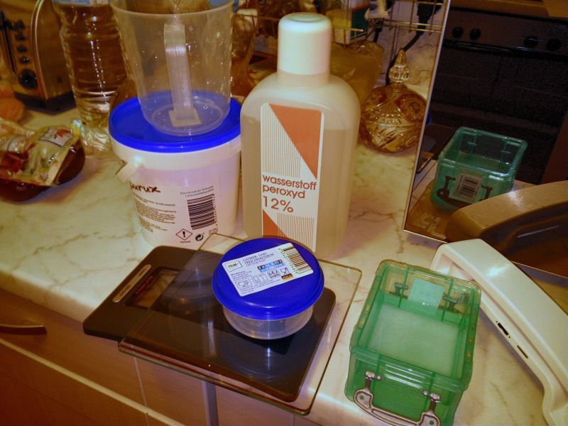
After I diluted the solution, I put the container in the sink with warm water, the water should not be hotter than 40-45 degrees.
Example
It turned out, in principle, not bad, unfortunately I only have photos of the first version, but there were mistakes.
There was some problem with usb, I decided to use micro usb to reduce, I had a few pieces, but I did not know how to attach them. It looks like this:
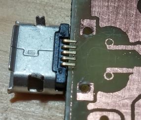
As you can see, there is nothing here to fix it to the board, you can solder only for two side projections, which I did. The mount was very weak and even when testing everything came off.
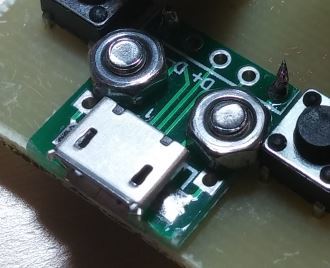
Then I ordered small boards, where micro usb was already attached. Something like this:
Pay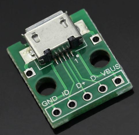
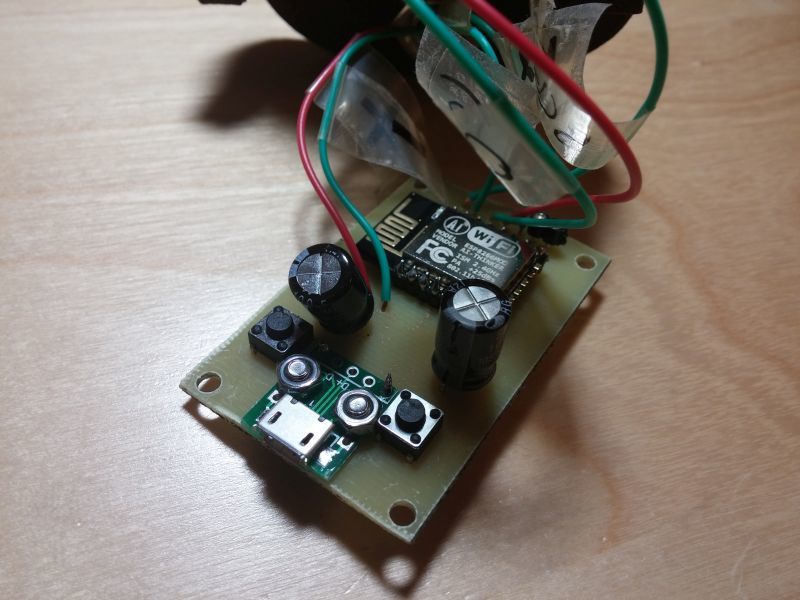
I screwed all this with bolts - it was a good decision, it still works.
At the end it looked like this.
Both sides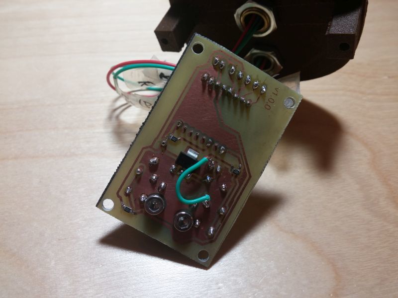
Housing
In homemade crafts this is often a big problem, everything is done neatly and beautifully. When I started the project, I didn’t have a 3D printer yet, but from the very beginning I wanted to print the case. I thought that you can order it somewhere. When searching where you can print the case, I decided that it is better to buy a 3D printer. In principle, there were no special requirements, the main thing is to print normally and not cost much. Stopped at "Anet A8". Surprisingly well prints, really long.
Then I created a 3D model of the case, I recognized only the third option as successful.
Failed options


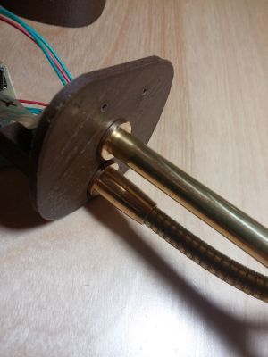
These are 3d models that I made for the case. Inside the case lies the weighting agent, as opposed to the sphere above, so the case turned out somewhat high.
Photo closer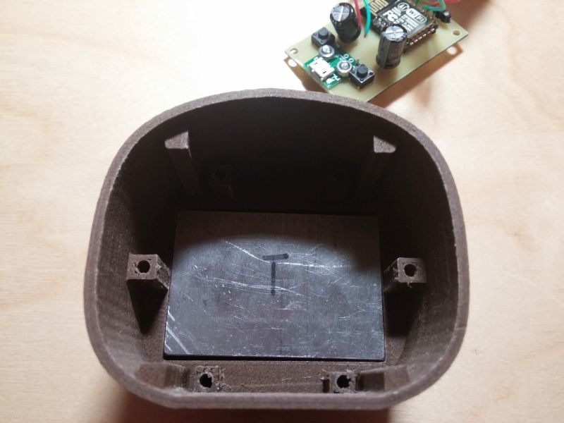
All together it looks like this:

Photo cover. She had to practically hammer into the hull. Two small holes on the top need to be able to push the buttons. The solution is not very successful, you need something thin and long, and besides, you still need to find the buttons inside to the touch. In principle, I find it without problems, but it will be hard for someone without training.
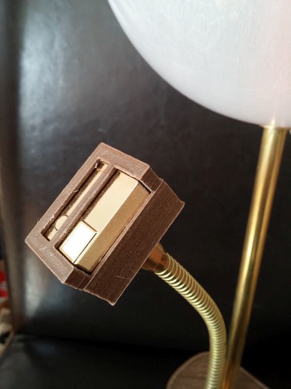
So I keep the RGB LED in the ball above:

A couple of other photos

Conclusion
Even at first did not know what would such a clever write. I thought maybe some problems list, there were many.
In fact, the project turned out more for training. When I first started doing it, sometime last year in the summer, it seemed to me a useful device and with some pretense to design, and in general it had to be beautiful. But now, when I did, somehow the not very necessary thing turned out to be, although it looks like nothing (my wife likes it), she is now standing in the corner (turned off).
I finished the firmware somewhere at the beginning of December and already forgot about a lot of things written, so in terms of training, too, some controversial moment turned out.
Now I would not do that, instead of a ball, I would attach something small, like a sea lighthouse.
The whole project lies on the githaba . There is both a divorced board and a code, as well as 3D models (if someone wants to print all this). The tubes, by the way, are M10x20mm.
PS: A few moments about me personally:
1. This is my first article, maybe I read a lot here, but still treat with understanding.
2. The firmware is not written very well, maybe someone wants to redo it.
3. I apologize in advance for the abundance of English words, I have not lived in a Russian-speaking country since I was 16, and therefore I often don’t know what some things are called in Russian.
Source: https://habr.com/ru/post/402625/
All Articles