History of a single spectrum analyzer

I sometimes wonder why I am very interested in some things and not at all interested in others, because interest is what helps for days without feeling tired, being engaged in the subject of interest and at the same time if it fades away, you can hardly make yourself do something. From where it comes, where it goes incomprehensibly, it’s only clear that as long as it is there is no time to waste, you have to do what is interesting because interest will sooner or later go away, but the experience will remain.
So it was this time, working some time ago as an auto electrician, I was interested in the question - “how do you know if the alarm system works and how do they differ?”.
')
What ended this story read under the cut.
As time went on, I changed the job, but the interest and desire to sort it out remained.
Once again, walking across the expanses of the Internet, I stumbled upon the rf explorer and realized that this was what I needed, though the price confused me, it seemed to be a “meter”, and was not rated for power, but cost $ 130.
I do not like such purchases, it is better to postpone this money and in the future to buy a full-fledged analyzer, and try to collect this one yourself, as judging by the photo from the Internet, it is built on just one si4313 chip. By that time I already had experience with displays and MK, so I ordered si4313 on Ali and started reading datasheet.
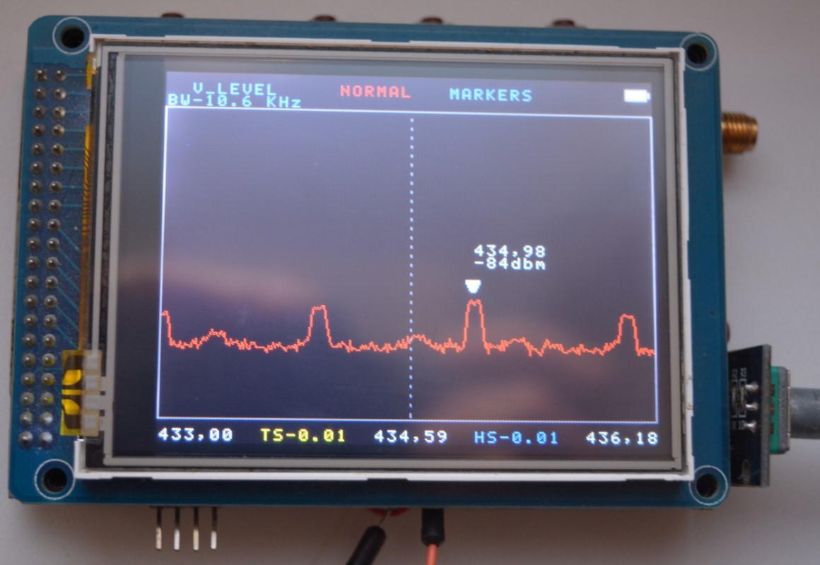
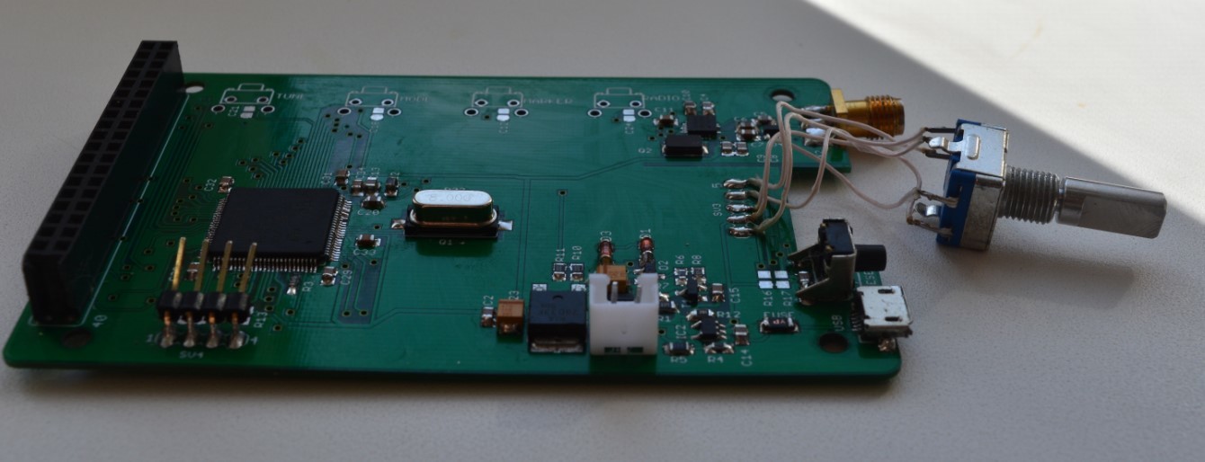
After the chip arrived, it took quite a bit of time to launch it. The first stage is completed, the next stage is a description of the operation of the device and the development of the scheme, according to the written TZ. It was modest, so the scheme was quickly designed, the board was drawn and assembled. And here the most difficult moment came for me - it was the development of the interface, although what kind of development there was, it was necessary to decide how to arrange the elements on the screen so that they looked beautiful, and also to choose colors. As a result, a lot of trial and error has turned out, such an interface.
After the device shown in the picture was ready, I was satisfied, some of the curtains were ajar and the development stopped. Usually, when I do something for myself, it always happens, for a while I concentrate on the development as much as possible until I achieve a satisfying result and forget about the project for a month or two.
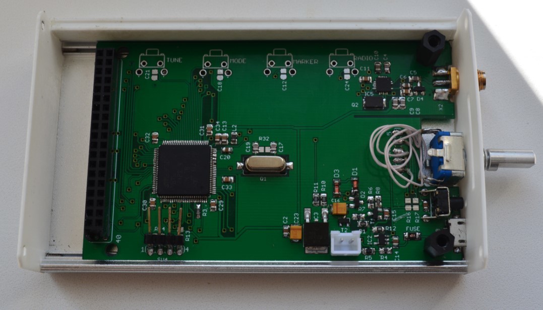
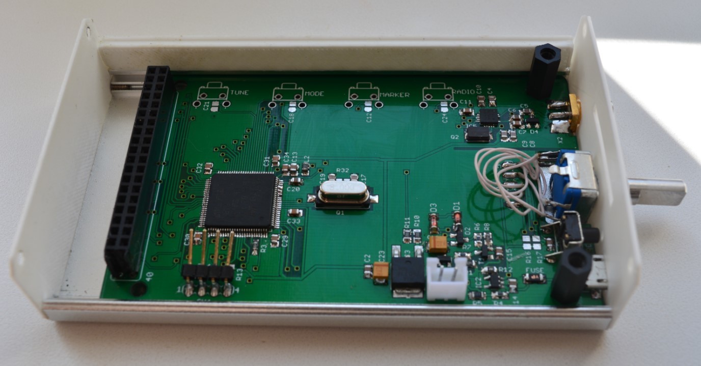
A few months later, I decided that it would still be good to order a fee at the factory and pack the whole thing in the case. An aluminum case was found on Ali, a board was redrawn under it, then the case and the board were ordered. The development again stopped for a while while orders were going, that is, for a month.
When the parcels arrived, it turned out that the case did not fit in height, I had to upgrade it using inserts printed on a 3D printer. Over the next few days the device was assembled, the interest was fully satisfied and the development was again left. At that time, he had the following characteristics:
- frequency range 240 - 960 MHz
- minimum bandwidth - 3.18MHz
- maximum span - 636MHz
- adjustable input bandwidth - 10.6 kHz / 24.0 kHz / 56.2 kHz / 112.1 kHz / 225.1 kHz / 335.5 kHz / 420.2 kHz / 620.7 kHz
- adjustable scanning step - 10kHz / 50kHz / 100kHz / 500kHz / 1MHz / 1.5MHz / 2MHz
- sensitivity - -98 ... -118dBm
- current consumption - 170mA
- saving screenshots on sd card
The control was carried out using a 3.2 ”resistive touch screen and an encoder, although the board has space for mechanical buttons, but they did not fit into this case.


After some time, I realized that it would be very convenient to be able to take screenshots, and in a couple of weeks I screwed a card to the sd analyzer, since I had the option of connecting it at the PC wiring stage. Only a few simple but important questions remain, what is the error in the power readings and does it work in the whole range. Before that, he used it to check the keyfobs from the alarm system, that is, at frequencies of 315 and 433MHz, but he did not know if it worked correctly in the rest of the range.
In order to answer questions, an RF generator from dernuss was assembled, described here and tested. I was pleased with the result, the analyzer saw it in the whole range, but it didn’t work out the power, it turned out that the generator was not rated for power, and in its settings you can only choose the attenuation of the signal from the maximum it can produce.
When I published the last article about the oscilloscope, I wrote to the engine9 to me personally and offered to work on the design of the donkey's interface, but then I had other plans and I refused, saying that I am planning another version on a 303 chip, and we will work on it. After some time we wrote off and had to start work on the donkey. Once in a conversation, I mentioned that I did the analyzer and wanted him to look at it with his creative look and suggest what can be corrected, since I definitely didn’t like some design moments. He looked and started ... In general, we started working on the design of the analyzer, that's what happened in the end.
Of course, it’s impossible to call this device a spectrum analyzer, it’s more like a “display meter” and it will never be an analyzer, because the developer of such a device has practically no influence on the operation of the si4313 chip, that is, if the chip in some range goes blind and gives an incorrect result , fix it will not work. Fortunately, such bugs have not been noticed yet, but the tester was alone))
If anyone has a desire to join testing, write in a personal, I can send a couple of devices without a case and battery.
It took more than a year to create something that has been interrupted; it is impossible to say that something has been done, as a matter of fact, a lot of fuss about emptiness, interest has gone, and experience has been gained.
Update: I received a few emails from which it became clear that I had to express my thoughts more clearly. I do not send devices for free or at cost, but I send them, in my opinion, at a low price.
Source: https://habr.com/ru/post/402603/
All Articles