Winstar Graphic and Text Display Mode
Graphic displays, including the type of OLED, most represented in our market by Winstar, have far less demand in relation to lowercase and publications on their use are also much smaller. Meanwhile, graphic OLED displays, due to the lack of reference to the font tables of a predefined pattern, provide the best way to get ergonomic indicator devices for a wide variety of needs. And it turned out that the graphics mode in the WS0010 controller is initiated easier and more stable than the text one.
Before proceeding to the consideration of the actual graphic displays, consider the evergreen problem with the problems of turning on the text mode of the WS0010 controller, which received an unexpected and obvious solution (oh, where were my eyes!).
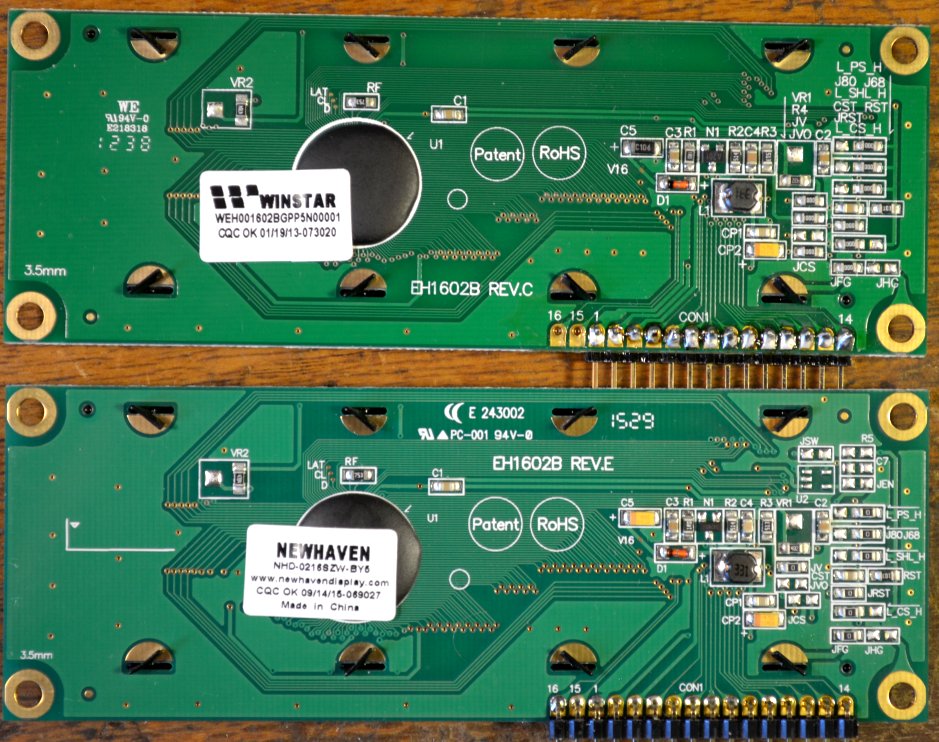
It is well known that Winstar line displays have stability problems during initiation. It turned out, by the way, that this is not only characteristic of the “damned Chinese”: the samples of Newhaven Display 16x2 I found with great difficulty, located on the other side of the globe, are externally a complete copy of Winstar, except for the location of some of the inscriptions and the name of the company on same form and same font):
')
Containing, as it is written in datasheets, a certain “LCD comparable” controller, these displays behave completely identical to Chinese and have the same drawbacks. Obviously, there is no time to spend on checking other companies, like Midas, judging by this publication , and there was no international cooperation. Globalized economy rulez!
The difficulties of the text mode are expressed in the fact that at startup (for example, when rebooting or manually resetting the program of the controlling controller), garbage may appear on the displays, and lines 0 and 1 randomly change places. Experiments have shown that it does not depend on the inclusion method (8-bit or 4-bit). This issue is especially acute when a periodic software reboot is necessary, for example, using a Watchdog timer.
Part of the problem is solved by a careful attitude to power (from a separate source, and in no case from USB Arduino), and a separate reboot through turning off and on the power of the display after launching the control program (see the previous publication of the author). As it turned out, the author of these lines is not the only one who offered a similar solution to the problem: the author of the add-on over LuquidCrystal called WinstarOLED also included a special pw_pin, with which the display power is distorted when the program starts.
But this is all, of course, initiative and half measures. Someone SeregaB ran into a radical way (see his publication on easyelectronics.com - thank Tomasina for the tip). He actually set a completely different task: to learn how to work just with the graphic, rather than the text mode. Trying to switch between the modes, he quickly discovered that “ switching to the graphic mode was normal, and from graphic to“ text ”it was very clumsy .” Then he recalled that " sometime, long ago, when the LH was still printed on paper, I read in some of the LH on the HD44780 that mode switching should be done only when the screen is off ." And it all worked.
From the cited publication, I will simply reproduce here two switching procedures, adapting them somewhat for use in conjunction with LuquidCrystal (an instance of the class is called OLED1 here).
Switch to graphic mode:
Switch to text mode:
As we will see later, the first procedure is not very necessary: WS0010 switches to graphic mode from a half-ping; it is enough to send the command 0x1F to it. But the second sequence of teams was very business. For the sample, it was included directly into the sketch using LuquidCrystal in this form:
Then this function was called in setup immediately after the library was initiated:
If you add some delay (500) before this, the demonstration turns out to be very visual: after pressing the reset button of the Arduino board on the screen, as usual, garbage appears, but only for a moment: after the function is triggered, the screen is cleared and all lines appear in their places .
The function works the same way, but for convenience, I replaced this sequence of commands with the contents of the LiquidCrystalRus :: clear () function in the file of the updated LiquidCrystalRus_OLED.cpp library, which was discussed earlier (recall that you can download it from the author’s site). Expectations of the command in the library is not provided, because for reliability after each command there in the general style of the library inserted delays of 100 μs. In the sketches that use this version of LiquidCrystalRus_OLED, at the beginning of the setup, you must call the clear () function, and it will also clean the screen at the same time.
Now let's do, finally, the graphics mode.
To begin with, I tried to switch the text display WEH001602BG I had to the graphic mode. Note that the graphic 100x16 and the text (configuration 20x2, the 16x2 is just less than the horizontal dots) of the displays are identical to the matrix, only the text one is separated by spaces on familiarity. This greatly limits the use of graphics mode in text displays, and even more text mode in graphics. But to test how it works, you can use any of them.
The display along with the DS1307 clock connected to the Arduino Nano as follows:

According to the same scheme, we will connect further graphic displays. The gray color in the diagram shows the connection of the second display, if necessary.
You can use the improved procedure from the previous section to switch to the graphics mode, but a simple function from one command works quite well:
We don’t need any Russian table here, so the standard (unaligned) LiquidCrystal is used, which works flawlessly in graphics mode. In order not to bother with debugging all library options, in the case when textual and graphical versions of displays are included in parallel, I use my own library for everyone (for textual upgraded Rus_OLED, for graphic ones). Connection can still be done to the same legs of the controller, except for the conclusions of the resolution E, according to the above scheme.
Further, I partially used the author's workings of the mentioned WinstarOLED library (in itself, this add-on above LuquidCrystal is unfinished, and it is not advisable to use it as is). He introduced the convenient function of setting the graphic cursor (the error of the original is corrected here in the part of the maximum x value):
The constant LCD_SETDDRAMADDR is defined in the LiquidCrystal library. Display 100x16, like text, is divided into two lines 0 and 1, because y here can take only two values. And the horizontal x coordinate varies from 0 to 99. By the set coordinate, the lcd.write () command sends a byte, the individual bits of which determine the luminous positions of the vertical line with a length of 8 points. The leftmost position in the top row has coordinates of 0.0, the rightmost one in the bottom position is 99.1. And the top point will correspond to the low bit, and the bottom point will correspond to the high bit.
For the convenience of coding images, I wrote out a label in which you can quickly create the necessary code manually. For full font tables, of course, it is advisable to use special editors (of which there are at least a million different degrees of independent activity), but 10 digits with the required bit order are faster processed manually, especially since automatically created fonts often still have to be finished. In accordance with the above, the glyph, for example, the numbers 2 in 10x16 will be encoded as follows:
All this is written in a two-dimensional array of the form:
For each digit 0-9, a separate such array Data0, Data1, Data2 and so on is created. For hours, except numbers, you will need a double point. It can be made shorter:
Since in the graphic mode the controller does not know how to "blink", it is necessary to blink with a colon programmatically. You can also extinguish a double point by simply outputting zeros to the corresponding positions, but for uniformity I made a separate array
For the output of each digit and separately for a double point, a separate function is written:
All functions are the same, but use different arrays, and for a double point and other limits of the cycle. It turned out not too economically in terms of the amount of code (see more on this later), but it is clear and easy to correct errors. Gaps between characters are taken into account at the output stage, indicating the corresponding position (the RTClib library is used to read the clock):
Ten digits of 20 bytes each will occupy 200 bytes in memory — about 10% of its volume (and the 16x16 wide font, as in the example below, and all 16%). Full monolingual font of this size, along with numbers, without taking into account all punctuation marks and specials. characters, contains from 62 (English) to 74 (Russian without E) characters, the value will take up almost half of the ATmega328 RAM. Because tricks with arrays and output functions separately for each character will have to be canceled, and do as expected. That is, the fonts should be left in the program memory and loaded through PROGMEM, and all glyph drawings should be designed as a single font array, and loaded for display by character number in a single table. Otherwise, the memory is not enough and the program code will swell up to unmanaged volume. We will not dwell on this here, because in our simple examples all this is not required - we will be limited each time to a small strictly necessary number of characters.
Due to the large size of the full text of the GraphicOLED_DC1307 sketch, I don’t cite it, you can download it here . The text contains the resetOLED function, which distorts the power of the display when the controller is rebooted (via pwrPin D2), but it was never needed, so you can safely remove it. The result of the program is shown in the photo:
Unfortunately, simultaneous stay in text and graphic mode is excluded, because if you want to use the remaining space, you will have to draw your own fonts (there is space for about 7 characters of the 5x7 font on each line).
When, finally, the ordered graphic displays of the WEG010016AL arrived, I began by trying to enter them into text mode in order to see what would come of it.
To test the text mode, a program for simulating a clock-calendar display with an external temperature sensor, described in a previous publication, was downloaded. The result made me remember that different Winstar displays can be differently oriented with respect to the connector (in this case, the WEG010016A connector is at the top, the text WEH001602B, which we used above, at the bottom, at type C, generally at the side):
With the orientation of the display we will understand further, but for now let's see what happened. But it turned out nothing good: the text mode (of course, equipped with a crutch, which was discussed at the beginning of the article) works flawlessly, but in practice it is useless to use it due to the absence of gaps between the characters. Therefore, we will not linger on it, but proceed to consider the graphics mode.
The procedures for installing the graphics mode are the same as those discussed above for the text version. It remains to deal with the flip of the display, if it has a connector at the top relative to the screen. Of course, you can just flip the display, but the position with the connector facing down seems more natural and comfortable to me. In addition, when using a type with a connector on the side, it may be necessary to orient the connector to the right and not to the left. For the upside-down orientation, you need to convert the image — that is, swap the first and last positions horizontally, the rows, and reverse the order of the bits in the bytes that make up the array (with the lower bit corresponding to the bottom point).
Since I had already painted ten digits for the previous case, for the last task it was necessary to introduce the procedure of program reversion:
You can change the order of the horizontal coordinates and vertical lines by making changes to the setGraphicCursor function:
The output functions of the array of each digit remain the same, only the reversion of bits is added:
The full sketch of the GraphicOLED_DC1307_100x16 watch can be downloaded from here , and the result for the WEG010016AL display is shown in the photo:
But on this photo a different type of font (16x16) on the display WEG010016CG (the display is also upside down):
If you create the font again, changing the order of the bits manually, then you do not need reversion and the program will run faster (although there are no noticeable delays to the eye). But the above procedure is a bit of a coup useful in any case - to display various pictures. For example, from one arrow pointing up and right, programmatically, you can get four directions at once.
The photo below shows the result of the procurement program of the display of the wind speed and wind direction sensor. As you can see, it turned out to be very easy to implement in one line fonts of different sizes together with pictures:
In conclusion, I will add that here is a very interesting library for working with WS0010 in graphic and text modes for SPI. In text, it mostly copies Liquid Crystal (and what else can you think of?), And in graphic it has functions for drawing graphic primitives, embedded fonts (thick, like mine, and the usual 5x7) and much more.
Before proceeding to the consideration of the actual graphic displays, consider the evergreen problem with the problems of turning on the text mode of the WS0010 controller, which received an unexpected and obvious solution (oh, where were my eyes!).
Problem solving text mode WS0010
It is well known that Winstar line displays have stability problems during initiation. It turned out, by the way, that this is not only characteristic of the “damned Chinese”: the samples of Newhaven Display 16x2 I found with great difficulty, located on the other side of the globe, are externally a complete copy of Winstar, except for the location of some of the inscriptions and the name of the company on same form and same font):
')
Containing, as it is written in datasheets, a certain “LCD comparable” controller, these displays behave completely identical to Chinese and have the same drawbacks. Obviously, there is no time to spend on checking other companies, like Midas, judging by this publication , and there was no international cooperation. Globalized economy rulez!
The difficulties of the text mode are expressed in the fact that at startup (for example, when rebooting or manually resetting the program of the controlling controller), garbage may appear on the displays, and lines 0 and 1 randomly change places. Experiments have shown that it does not depend on the inclusion method (8-bit or 4-bit). This issue is especially acute when a periodic software reboot is necessary, for example, using a Watchdog timer.
Part of the problem is solved by a careful attitude to power (from a separate source, and in no case from USB Arduino), and a separate reboot through turning off and on the power of the display after launching the control program (see the previous publication of the author). As it turned out, the author of these lines is not the only one who offered a similar solution to the problem: the author of the add-on over LuquidCrystal called WinstarOLED also included a special pw_pin, with which the display power is distorted when the program starts.
But this is all, of course, initiative and half measures. Someone SeregaB ran into a radical way (see his publication on easyelectronics.com - thank Tomasina for the tip). He actually set a completely different task: to learn how to work just with the graphic, rather than the text mode. Trying to switch between the modes, he quickly discovered that “ switching to the graphic mode was normal, and from graphic to“ text ”it was very clumsy .” Then he recalled that " sometime, long ago, when the LH was still printed on paper, I read in some of the LH on the HD44780 that mode switching should be done only when the screen is off ." And it all worked.
From the cited publication, I will simply reproduce here two switching procedures, adapting them somewhat for use in conjunction with LuquidCrystal (an instance of the class is called OLED1 here).
Switch to graphic mode:
OLED1.command(0x08);// OLED1.command(0x1F);// OLED1.command(0x01);// (.. clear()) OLED1.command(0x08|0x04);// Switch to text mode:
OLED1.command(0x08);// OLED1.command(0x17);// OLED1.command(0x01);// (.. clear()) OLED1.command(0x04 | 0x08);// As we will see later, the first procedure is not very necessary: WS0010 switches to graphic mode from a half-ping; it is enough to send the command 0x1F to it. But the second sequence of teams was very business. For the sample, it was included directly into the sketch using LuquidCrystal in this form:
void reset_textmode() // { OLED1.command(0x08);// OLED1.command(0x17);// OLED1.command(0x01);// OLED1.command(0x04 | 0x08);// } Then this function was called in setup immediately after the library was initiated:
. . . . . OLED1.begin(16,2); //16 2 reset_textmode(); // clear() . . . . . If you add some delay (500) before this, the demonstration turns out to be very visual: after pressing the reset button of the Arduino board on the screen, as usual, garbage appears, but only for a moment: after the function is triggered, the screen is cleared and all lines appear in their places .
The function works the same way, but for convenience, I replaced this sequence of commands with the contents of the LiquidCrystalRus :: clear () function in the file of the updated LiquidCrystalRus_OLED.cpp library, which was discussed earlier (recall that you can download it from the author’s site). Expectations of the command in the library is not provided, because for reliability after each command there in the general style of the library inserted delays of 100 μs. In the sketches that use this version of LiquidCrystalRus_OLED, at the beginning of the setup, you must call the clear () function, and it will also clean the screen at the same time.
Note
There is one misunderstanding with clearing the screen: in the command table in the datasheet it is noted that the 0x01 command can last as much as 6.2 ms “when fsp or fosc = 250KHz”. What kind of “fsp or fosc” is actually in specific controllers, they are too lazy to write, but in any case, even if they are megahertz, the delay for this command should be significant (and the author of this article mentions). However, in practice it turns out that the cleaning team works quite well and if there is no delay at all. So I did not understand, and acted according to the well-known programmer rule: “it works - do not touch!”.
Now let's do, finally, the graphics mode.
Graphic mode in text displays WEH001602
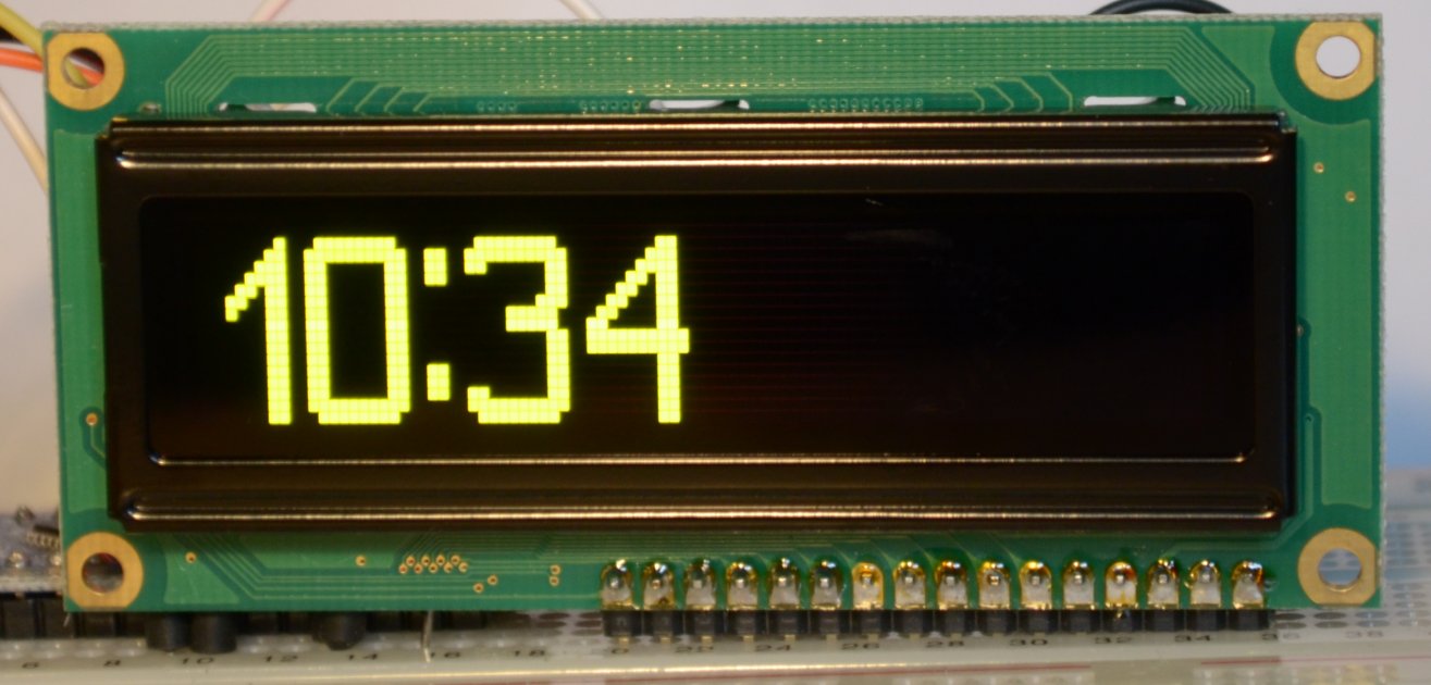
To begin with, I tried to switch the text display WEH001602BG I had to the graphic mode. Note that the graphic 100x16 and the text (configuration 20x2, the 16x2 is just less than the horizontal dots) of the displays are identical to the matrix, only the text one is separated by spaces on familiarity. This greatly limits the use of graphics mode in text displays, and even more text mode in graphics. But to test how it works, you can use any of them.
The display along with the DS1307 clock connected to the Arduino Nano as follows:
According to the same scheme, we will connect further graphic displays. The gray color in the diagram shows the connection of the second display, if necessary.
You can use the improved procedure from the previous section to switch to the graphics mode, but a simple function from one command works quite well:
. . . . . #define LCD_SETGRAPHICMODE 0x1f LiquidCrystal lcd(9, 4, 8, 7, 6, 5); void setGraphicMode(){ lcd.command(LCD_SETGRAPHICMODE); } . . . . . We don’t need any Russian table here, so the standard (unaligned) LiquidCrystal is used, which works flawlessly in graphics mode. In order not to bother with debugging all library options, in the case when textual and graphical versions of displays are included in parallel, I use my own library for everyone (for textual upgraded Rus_OLED, for graphic ones). Connection can still be done to the same legs of the controller, except for the conclusions of the resolution E, according to the above scheme.
Further, I partially used the author's workings of the mentioned WinstarOLED library (in itself, this add-on above LuquidCrystal is unfinished, and it is not advisable to use it as is). He introduced the convenient function of setting the graphic cursor (the error of the original is corrected here in the part of the maximum x value):
void setGraphicCursor( uint8_t x, uint8_t y ){ if( 0 <= x && x <= 99 ){ lcd.command(LCD_SETDDRAMADDR | x); } if( 0 <= y && y <= 1 ){ lcd.command(LCD_SETCGRAMADDR | y); } } The constant LCD_SETDDRAMADDR is defined in the LiquidCrystal library. Display 100x16, like text, is divided into two lines 0 and 1, because y here can take only two values. And the horizontal x coordinate varies from 0 to 99. By the set coordinate, the lcd.write () command sends a byte, the individual bits of which determine the luminous positions of the vertical line with a length of 8 points. The leftmost position in the top row has coordinates of 0.0, the rightmost one in the bottom position is 99.1. And the top point will correspond to the low bit, and the bottom point will correspond to the high bit.
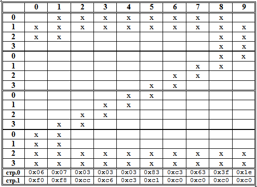
For the convenience of coding images, I wrote out a label in which you can quickly create the necessary code manually. For full font tables, of course, it is advisable to use special editors (of which there are at least a million different degrees of independent activity), but 10 digits with the required bit order are faster processed manually, especially since automatically created fonts often still have to be finished. In accordance with the above, the glyph, for example, the numbers 2 in 10x16 will be encoded as follows:
All this is written in a two-dimensional array of the form:
const byte Data2[2][10]={{0x06,0x07,0x03,0x03,0x03,0x83,0xc3,0x63,0x3f,0x1e}, {0xf0,0xf8,0xcc,0xc6,0xc3,0xc1,0xc0,0xc0,0xc0,0xc0}}; For each digit 0-9, a separate such array Data0, Data1, Data2 and so on is created. For hours, except numbers, you will need a double point. It can be made shorter:
const byte DataDP[2][2]={{0x70,0x70}, {0x1c,0x1c}};// Since in the graphic mode the controller does not know how to "blink", it is necessary to blink with a colon programmatically. You can also extinguish a double point by simply outputting zeros to the corresponding positions, but for uniformity I made a separate array
const byte DataDPclr[2][2]={{0x00,0x00}, {0x00,0x00}};// . For the output of each digit and separately for a double point, a separate function is written:
void draw2 (byte x/* */) // “2” { for (byte i = x; i<x+10; i++){ setGraphicCursor(i, 0); lcd.write(Data2[0][ix]); setGraphicCursor(i, 1); lcd.write(Data2[1][ix]);} } All functions are the same, but use different arrays, and for a double point and other limits of the cycle. It turned out not too economically in terms of the amount of code (see more on this later), but it is clear and easy to correct errors. Gaps between characters are taken into account at the output stage, indicating the corresponding position (the RTClib library is used to read the clock):
void loop() { DateTime clock = RTC.now(); if (clock.second()!=old_second) { uint8_t values; values=clock.hour()/10; // drawValPos(values,0); values=clock.hour()%10; // drawValPos(values,12); values=clock.minute()/10; // drawValPos(values,28); values=clock.minute()%10; //end drawValPos(values,40); if (clock.second()%2) drawDP(24); else drawDPclr(24); old_second=clock.second(); }//end if clocksecond } Ten digits of 20 bytes each will occupy 200 bytes in memory — about 10% of its volume (and the 16x16 wide font, as in the example below, and all 16%). Full monolingual font of this size, along with numbers, without taking into account all punctuation marks and specials. characters, contains from 62 (English) to 74 (Russian without E) characters, the value will take up almost half of the ATmega328 RAM. Because tricks with arrays and output functions separately for each character will have to be canceled, and do as expected. That is, the fonts should be left in the program memory and loaded through PROGMEM, and all glyph drawings should be designed as a single font array, and loaded for display by character number in a single table. Otherwise, the memory is not enough and the program code will swell up to unmanaged volume. We will not dwell on this here, because in our simple examples all this is not required - we will be limited each time to a small strictly necessary number of characters.
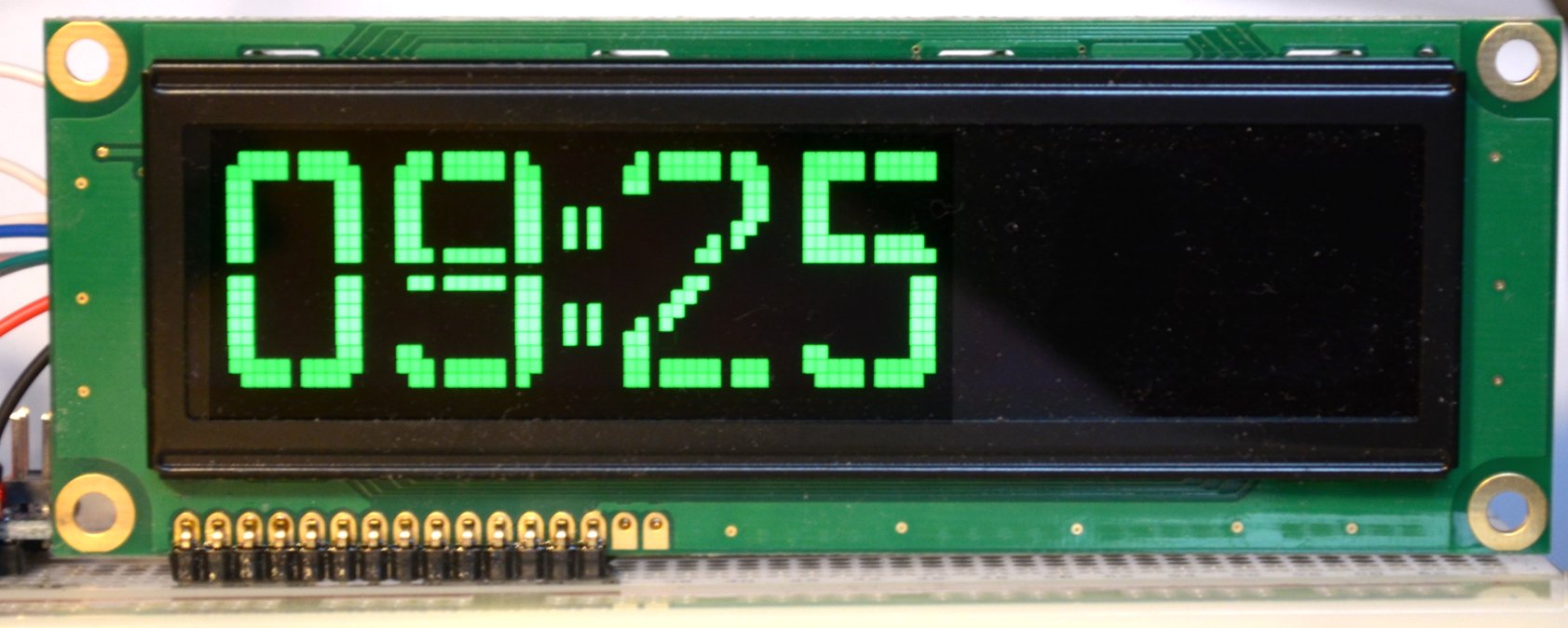
Due to the large size of the full text of the GraphicOLED_DC1307 sketch, I don’t cite it, you can download it here . The text contains the resetOLED function, which distorts the power of the display when the controller is rebooted (via pwrPin D2), but it was never needed, so you can safely remove it. The result of the program is shown in the photo:
Unfortunately, simultaneous stay in text and graphic mode is excluded, because if you want to use the remaining space, you will have to draw your own fonts (there is space for about 7 characters of the 5x7 font on each line).
Graphic display WEG010016A
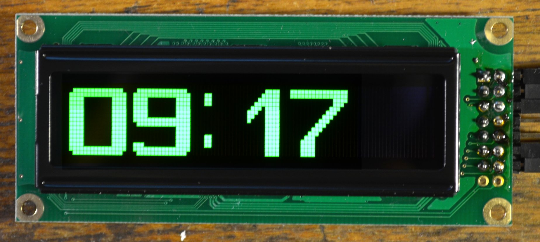
When, finally, the ordered graphic displays of the WEG010016AL arrived, I began by trying to enter them into text mode in order to see what would come of it.
To test the text mode, a program for simulating a clock-calendar display with an external temperature sensor, described in a previous publication, was downloaded. The result made me remember that different Winstar displays can be differently oriented with respect to the connector (in this case, the WEG010016A connector is at the top, the text WEH001602B, which we used above, at the bottom, at type C, generally at the side):
With the orientation of the display we will understand further, but for now let's see what happened. But it turned out nothing good: the text mode (of course, equipped with a crutch, which was discussed at the beginning of the article) works flawlessly, but in practice it is useless to use it due to the absence of gaps between the characters. Therefore, we will not linger on it, but proceed to consider the graphics mode.
The procedures for installing the graphics mode are the same as those discussed above for the text version. It remains to deal with the flip of the display, if it has a connector at the top relative to the screen. Of course, you can just flip the display, but the position with the connector facing down seems more natural and comfortable to me. In addition, when using a type with a connector on the side, it may be necessary to orient the connector to the right and not to the left. For the upside-down orientation, you need to convert the image — that is, swap the first and last positions horizontally, the rows, and reverse the order of the bits in the bytes that make up the array (with the lower bit corresponding to the bottom point).
Since I had already painted ten digits for the previous case, for the last task it was necessary to introduce the procedure of program reversion:
byte reverse(byte x) { byte result=0,i; for(i=0;i<8;i++) { if (x & (1 << i)) { result |= 1 << (7-i); } } return result; } You can change the order of the horizontal coordinates and vertical lines by making changes to the setGraphicCursor function:
void setGraphicCursor( uint8_t x, uint8_t y ){ if( 0 <= x && x <= 99 ){ lcd.command(LCD_SETDDRAMADDR | (99-x)); } if( 0 <= y && y <= 1 ){ lcd.command(LCD_SETCGRAMADDR | (1-y)); } } The output functions of the array of each digit remain the same, only the reversion of bits is added:
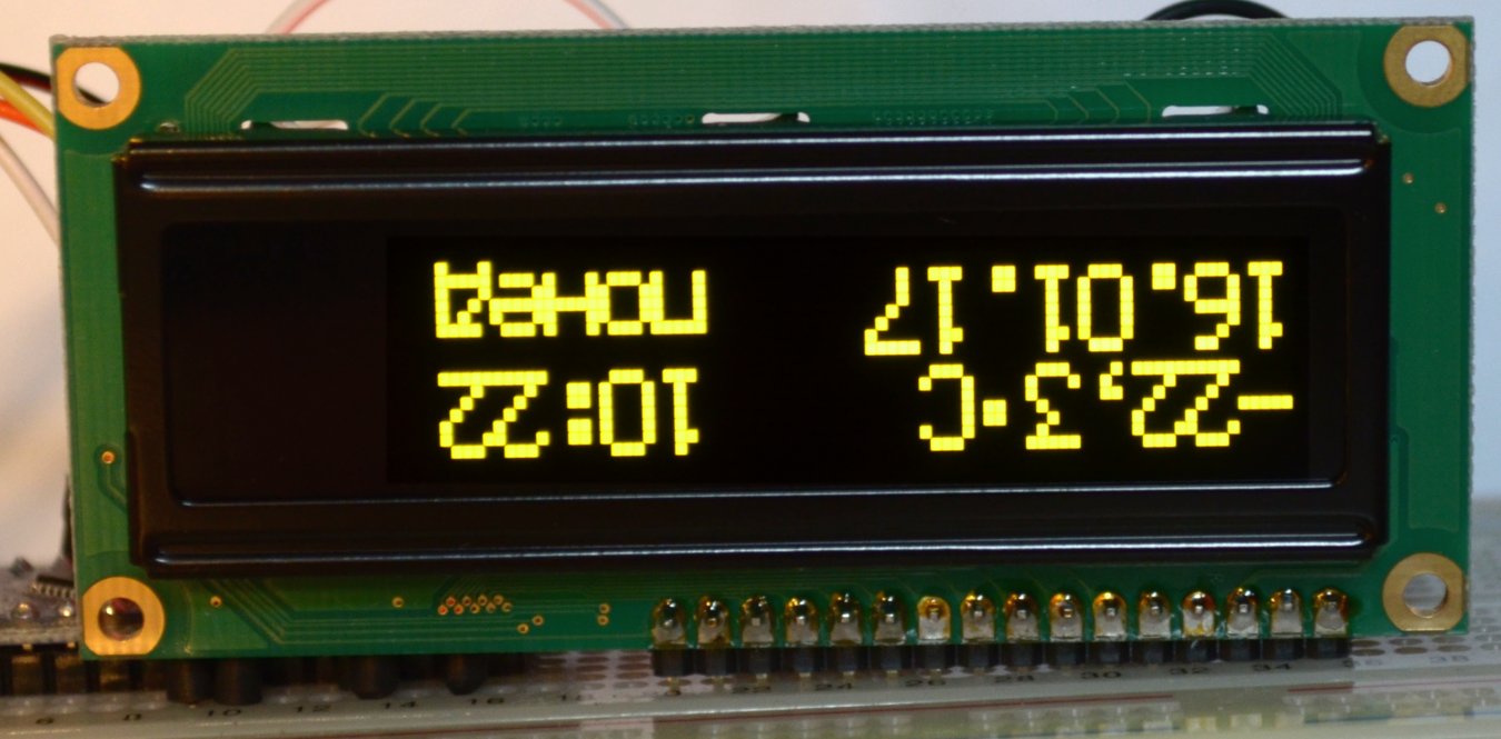
void draw2 (byte x/* */) // 2 { for (byte i = x; i<x+10; i++){ setGraphicCursor(i, 0); byte b=reverse(Data2[0][ix]); lcd.write(b); setGraphicCursor(i, 1); b=reverse(Data2[1][ix]); lcd.write(b);} } The full sketch of the GraphicOLED_DC1307_100x16 watch can be downloaded from here , and the result for the WEG010016AL display is shown in the photo:
But on this photo a different type of font (16x16) on the display WEG010016CG (the display is also upside down):
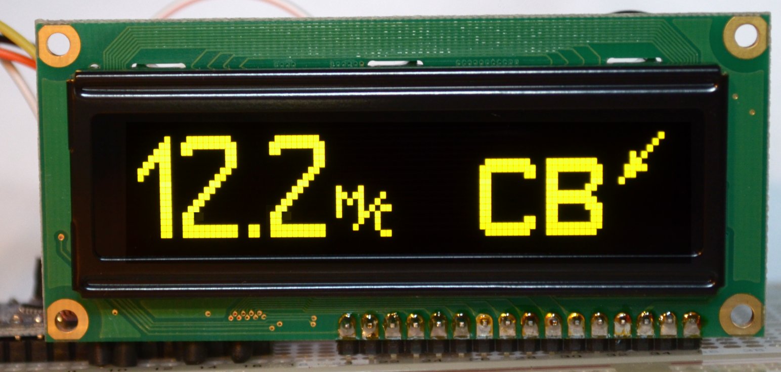
If you create the font again, changing the order of the bits manually, then you do not need reversion and the program will run faster (although there are no noticeable delays to the eye). But the above procedure is a bit of a coup useful in any case - to display various pictures. For example, from one arrow pointing up and right, programmatically, you can get four directions at once.
Drawing arrows
The picture and the arrow code (coordinates and bits in the table are inverted in accordance with the lower position of the connector for the WEG010016AL display, see above):

Output functions of multidirectional arrows:
const byte DataATR[2][8]={{0x00,0x00,0x00,0x00,0x00,0x00,0x00,0x00}, {0x01,0x02,0x04,0x28,0x30,0x78,0x60,0x80}}; Output functions of multidirectional arrows:
. . . . . void drawSW (byte x) // ( ) { for (byte i = x; i<x+8; i++){ setGraphicCursor(i, 0); lcd.write(DataATR[0][ix]); setGraphicCursor(i, 1); lcd.write(DataATR[1][ix]);} } void drawNW (byte x) // ( ) {// : for (byte i = x; i<x+8; i++){ setGraphicCursor(i, 0); byte b=reverse(DataATR[1][ix]); lcd.write(b); setGraphicCursor(i, 1); b=reverse(DataATR[0][ix]); lcd.write(b);} } void drawNE (byte x) // ( ) {// , for (byte i = x; i<x+8; i++){ setGraphicCursor(i, 0); byte b=reverse(DataATR[1][7-(ix)]); lcd.write(b); setGraphicCursor(i, 1); b=reverse(DataATR[0][7-(ix)]); lcd.write(b);} } void drawSE (byte x) // ( ) {// for (byte i = x; i<x+8; i++){ setGraphicCursor(i, 0); lcd.write(DataATR[0][7-(ix)]); setGraphicCursor(i, 1); lcd.write(DataATR[1][7-(ix)]);} } . . . . . The photo below shows the result of the procurement program of the display of the wind speed and wind direction sensor. As you can see, it turned out to be very easy to implement in one line fonts of different sizes together with pictures:
In conclusion, I will add that here is a very interesting library for working with WS0010 in graphic and text modes for SPI. In text, it mostly copies Liquid Crystal (and what else can you think of?), And in graphic it has functions for drawing graphic primitives, embedded fonts (thick, like mine, and the usual 5x7) and much more.
Source: https://habr.com/ru/post/402517/
All Articles