RobotDyn deals double blow: Mega + ESP8266
What does the developer do in rare leisure hours? That's right, looking through the prices of iron shops. I had a free minute and I decided to look through the pages of popular online stores - boring, nothing interesting, we have already seen all this ... and then suddenly my eyes fall on another Mega. Bah! Yes, this is not a simple Mega, but combined with all your beloved ESP8266, and even carefully equipped with switches for the joint operation of two controllers - wired (using Ethernet Shield) with a lot of GPIO and Wi-Fi for wireless communication.
Not bad! I thought and remembered AMS - there you can install two servers - wired and wireless and connect them to one system - ESP8266 will receive 54 digital and 16 analog pins, and Mega will receive wireless control via Wi-Fi and all the ESP8266 buns. Long time I did not come across such an interesting fee.
- Hello! Do you have a Mega + ESP8266 board?
- Yes, but we have only one left.
- Why only one?
- The rest dismantled.
- Reserve it, please, for me.
A few words about the company
I liked RobotDyn in two ways: first, with my technological solutions. There is no need to go far; an excellent example is the Mega + ESP8266 board under consideration. I have not seen anything like this in ours (and not ours, but I haven’t been looking for it) online stores. And this is not the only example, there is another version of Uno + ESP8266 and the company is clearly not going to stop at this, apparently there are still many interesting devices waiting for us.
')
And the second is its pricing policy. I will not dwell on this issue in detail here, but I will say that prices pleasantly surprised me - the company's motto “Prices are like on Aliexpress”.
I briefly described the background on which all subsequent events will unfold, now we go directly to the technical details and the description of the board and work with it.
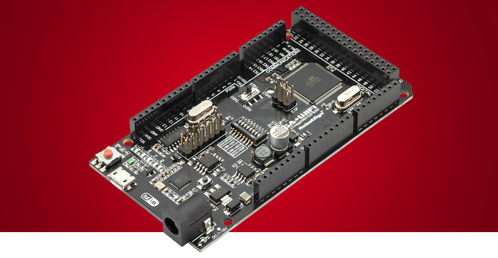
The board itself
In general, the usual board, not much different from many similar ones, if not for one small detail, namely, the ESP8266EX chip integrated into the board. This immediately translates the board into the category of extraordinary solutions. I want to draw your attention to one more detail - a non-standard ESP-12 module is integrated into the board, namely, the chip and all the wiring is done on the board itself, which transparently hints at the level of developers. I also want to note that the board has both a printed antenna and a connector for connecting an external antenna, which in many cases can be very useful.
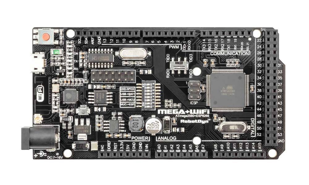
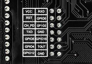
There are pin connectors on the board for connecting to the ESP8266 pins and a few switches that are worth mentioning a bit more about. The main idea of using the board is that using switches you can configure the interaction of its three components in different ways: the Atmega2560 chip, the ESP8266EX chip, and the USB-TTL CH340G converter. Both single and complex connections are possible, which allow you to organize many options for the interaction of all parts of the board. This opens up great opportunities for building various devices, but more on this later.
I would also like to note a decent load capacity of the board. Judging by the inscriptions on it, it is able to provide a load current of 1.6 A over a 5-volt channel and 1 A over a 3.3-volt one. Which is very good, especially in the aggregate.
There is nothing more to say about the board, let's proceed to installing the software and testing it.
Board testing
Since the board is integrated and there is practically no free space on it, and the wiring of the high-frequency part of the ESP8266EX is done on it, then at first there were doubts about the correct and problem-free operation of the entire economy.
Looking ahead, I will say that despite my concerns, everything works stably and as expected. We connect the switches on the Atmega2560 board to USB - we get the Arduino Mega, we connect the ESP8266EX to USB - we get the ESP8266, we switch to the Atmega2560 connection mode with the ESP8266EX we get the connection between the chips via the serial interface. Everything works exactly as described in the documentation and exactly as it is intuitively expected.
A huge plus of this decision is that the developers have taken care of coordinating the logical signal levels of all components of the system. Anyone who manually tried to configure the ESP8266 module and correctly connect all the pull-up resistors will understand me. There are no such problems here, all your work is reduced to clicking the switches on the board in accordance with the instructions from the manufacturer.
Stress Testing
How to test the board? You can load some standard sketch, but this will be a test about anything. This option can work normally, and in combat conditions the system will fail. Therefore, the work of both parts under the control of the corresponding versions of the Arduino Mega Server was chosen as a hard load test. For Mega, the Arduino Mega Server for Mega and for ESP8266, the Arduino Mega Server for ESP8266 in the M1 version.
The M1 distribution was chosen due to the fact that the board uses only 1 MB of flash memory for ESP8266. This, in my opinion, is almost the only mistake of the developers - in future revisions of the board I would recommend them to install 4 MB memory chips. The difference in price is small, and there are much more opportunities when using the 4 MB version. But since there is a version of AMS for systems with 1 MB, I did not pay much attention to this moment and continued testing.
What to say? We turn on the board, upload the software and get two independent servers. One wired via Ethernet Shield and one wireless via Wi-Fi. Beauty!
Separately, I would like to note that even the addition of Ethernet Shield with a card reader to this already heaped system did not cause any conflicts and failures - everything just worked as it should work. And in some cases it is even better than usual - this is the first board on which the ESP8266 firmware was successfully installed in the air in 100% of cases, on all other boards and modules from time to time there are failures during such a flashing.
And now two servers are spinning, loading the board, performing their duties and ... everything. Everything just works, even nothing to say, but this is probably the best praise for any technical system.
The most interesting
What I have described here is interesting from a purely academic point of view: an interesting fee, an interesting technical solution, but of course we are interested in its practical application. What is its practical and applied zest?
In that one switch on the board can connect two of its parts (Mega and ESP) into one whole and thus, firstly, to get a new quality of the system and, secondly, to compensate for the inherent disadvantages of each of its individual parts.
Let's start with ESP8266. The main disadvantage of this generally excellent solution is the catastrophic shortage of GPIO pins. As they say, one, two, and obchelsya. What the developers of this chip thought was hard to say, but before the release of ESP32 they had a little more time to think and in the new chip they fixed this deficiency. But we are dealing precisely with 8266.
This board allows you to make a knight's move and use all the power of Mega, and this, among other things, 54 digital and 16 analog outputs in the ESP8266. That is, our rickety ESP suddenly gets just bogatyr opportunities to work with sensors, actuators and other peripherals. It turns out, so to speak, baby ESP on steroids.
This is only one of the possible uses of the board lying on the surface.
Now look at the Mega. She does not interfere with the wireless interface and the ability to interact with Wi-Fi devices, which can provide it with integration with the ESP part of the system. And at the same time there is the possibility of parallel work on the wired Ethernet interface.
And this is also only one of the possible uses of this board, which lies on the surface.
Well, the various options for bridges: Ethernet - Wi-Fi, nRF24 - Ethernet, nRF24 - Wi-Fi, nRF24 (1) - nRF24 (2), nooLite - Wi-Fi, nooLite - Ethernet, nooLite (1) - nooLite (2 ), etc., etc., to infinity. You can route signals from dozens of subsystems with which the Arduino Mega Server runs between the two parts of the board and the interfaces connected to them.
I do not know what to say. Very cool.
Technical details
Now a little about the technical details. You see a table that shows all possible modes of operation of the board and shows all possible switch positions on it. Consider briefly each mode.

Arduino Mega 2560
The simplest mode of operation of the board, in the table it is designated as mode 3. If you set switches 3 and 4 to ON, and the rest to OFF, then you get the usual Arduino Mega 2560. Nothing interesting, for that it’s not worth buying this board, you can It was to buy the usual Mega.
ESP8266
Also not very interesting mode of operation. In the table, it is divided into two sub-modes, denoted as 1 (loading a sketch into ESP) and 2 (ESP connection mode with USB). This is all the functionality of a standard ESP8266 and for the sake of such use it was also not worth buying this board, it was possible to get along with the usual ESP module.
All independent
We do not consider this option at number 6 either, since all the links between the parts of the board are broken and it cannot be useful for anything for us.
The connection between Mega and ESP
In this mode, designated as 5, the connection is established between the Mega and ESP via the serial interface, but there is no connection to the USB-TTL converter. On ESP, the standard Serial is involved, and on Mega, at least the standard Serial3. The connection is stable and seamlessly running at a speed of 115200. This is a rather specific mode of operation, when no controller has USB connection. And so it is also not very interesting to us.
The connection between Mega and ESP and at the same time Mega and USB
But this is what is called the trump mode. We get everything at once - a Mega connection via USB and the ability to upload sketches to Mega and control its operation using the same USB, the ability to communicate between Mega and ESP and the ability to load sketches into ESP8266 and control its operation in the USB interface ... Mega! That is a complete stuffing, right on the spot.
This is the only correct mode of operation listed in the table. Remember his winning number which is equal to four. In the configuration of the switches on the board, it also looks beautiful - 1, 2, 3, 4 are in the ON position, the rest are OFF.
The attentive reader will ask: how can we load sketches into ESP8266 if the USB port is busy connecting to the Mega-part of the system? And this is the right question, the answer - no way. Why then do you write that we can upload sketches to ESP8266 in this configuration? Because the Arduino Mega Server has the ability to download sketches over the air directly from the Arduino IDE by pressing a couple of buttons, so everything is correct - we have full stuffing, everything works right away.
How to be to those who want to use the board without the Arduino Mega Server? There are only two options: either constantly click the switches, or add the ability to download sketches through the air to your designs. I personally prefer the second option.
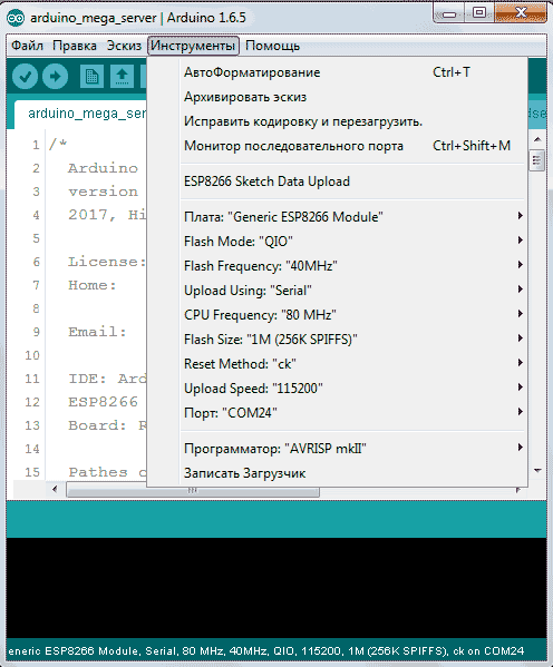
Arduino IDE settings
The Arduino IDE settings for Mega do not cause any questions, everything is standard there, and for the ESP8266 I’ll give a screenshot of the settings menu for a specific implementation of the ESP part on the RobotDyn board. You should set the same parameters for yourself, except for the port number - it will most likely have a different meaning on your system.
Arduino Mega Server for RobotDyn Mega + ESP8266
For this board, a special dual version of the Arduino Mega Server has been released, which contains two servers at once optimized specifically for this board. This is the external side of the question, both of these servers contain standard functionality and can be used for any of your projects.
You can use both of these servers independently of each other on the same board, or you can add the functionality you need and use them in tandem and in bridge mode between two networks and any interfaces connected to the servers.
In the first build of the Arduino Mega Server for the RobotDyn Mega + ESP8266, there is a test example of the interaction of two controllers over the Serial interface. This is a demonstration of the capabilities of technology based on which you can develop your own solutions.
Now a little more about the development of a protocol for the interaction of two controllers over a Serial interface in general and on this board in particular.
Protocol development
What should we build a house? Need to develop an interaction protocol between the two parts of the system via the Serial interface? - we will develop, the main thing here is to clearly and correctly set the task. To demonstrate the tandem operation of the system, we will display the indicators of the "partner" in the dashboard panel of each server.
A little about the terminology. For Mega, the “partner” is ESP8266, for ESP8266, respectively, Mega.
When the partner is working - the indicator will turn greenish when it is not working - red and gray, when the state is uncertain. This is very convenient - during operation, you will immediately see the state of the alter ego of your system.
For a practical solution to this problem, there are exactly a million ways. We will choose the following: the communication blocks of both parts of the system will be identical, the interaction will take place in full duplex mode, the information blocks will have a simple and clear format:
?= or
? This is just a test case for solving the task, you can modify this interaction protocol or write your own, suitable for your tasks. But on an already implemented protocol, you can not only monitor the status of the partner, but also apply it to many other purposes, for example, transfer the state of the controller pins, the state of the sensors, or send control commands to the partner.
Specifically, in our system, teams will look like this:
? mega = 1 - Mega sends information about its performance. The parameter "mega", the value "1".
? esp = 1 - ESP8266 sends information about its performance. The parameter "esp", the value "1".
So, for example, consider the implementation of the protocol for the Mega-part of the system.
In the standard way, we initialize the AMS module and the hardware Serial3 Mega at the speed of 115200.
void robotdynInit() { Serial3.begin(115200); modulRobotdyn = MODUL_ENABLE; started("RobotDyn", true); } We check the status of the Serial3 port and in the case of the arrival of data from the partner, we form a string variable serialReq containing the incoming data or commands.
void checkSerial() { while (Serial3.available() > 0) { if (sFlag) { serialReq = ""; sFlag = false; } char c = Serial3.read(); if (c == 10) { sFlag = true; parseSerialStr(); } else if (c == 13) { // skip } else { if (serialReq.length() < MAX_SERIAL_REQ) { serialReq += c; } } // if } // while (Serial3.available() > 0) } // checkSerial() Parsim commands and data and in the case of the arrival of information about the state of the partner, we take measures in the form of a change in the state of the esp variable.
void parseSerialCmd() { String command, parameter; if (serialReq.indexOf(F("?")) >= 0) { int pBegin = serialReq.indexOf(F("?")) + 1; if (serialReq.indexOf(F("=")) >= 0) { int pParam = serialReq.indexOf(F("=")); command = serialReq.substring(pBegin, pParam); parameter = serialReq.substring(pParam + 1); } else { command = serialReq.substring(pBegin); parameter = ""; } if (command != F("esp")) { Serial.print(F("command/parameter: ")); Serial.print(command); Serial.print(F("/")); Serial.println(parameter); } if (command == F("esp")) { if (parameter == F("1")) { esp = 1; espTimer = millis(); } else { esp = 0; } } } // if (request.indexOf(F("?")) >= 0) } // parseSerialCmd() You can easily add processing to any other commands by modifying and adding to the corresponding section of code.
if (command == F("esp")) { if (parameter == F("1")) { esp = 1; espTimer = millis(); } else { esp = 0; } In the case of using in-house projects and parsing a set of commands and data, this section of code is better arranged in the form of corresponding functions.
It remains to consider the standard function of the AMS module, which is responsible for its work. First, the status of the port is checked, then every four seconds a team is sent to the partner that Mega is alive and working and checks the time elapsed since the last data arrived from the partner and if it exceeds 8 seconds, it is concluded that the partner is not working.
void robotdynWork() { checkSerial(); if (cycle4s) { Serial3.println(F("?mega=1")); if (millis() - espTimer > 8000) { esp = 0; } } } That's all the magic. True, nothing complicated?
The full code of the module responsible for the intersystem communication between the Mega 2560 and ESP8266
/* Modul RobotDyn part of Arduino Mega Server project */ #ifdef ROBOTDYN_FEATURE bool sFlag = true; unsigned long espTimer = millis(); // Serial request #define MAX_SERIAL_REQ 32 String serialReq = ""; void robotdynInit() { Serial3.begin(115200); modulRobotdyn = MODUL_ENABLE; started("RobotDyn", true); } void printSerialStr() { Serial.print("["); Serial.print(serialReq); Serial.println("]"); } void parseSerialCmd() { String command, parameter; if (serialReq.indexOf(F("?")) >= 0) { int pBegin = serialReq.indexOf(F("?")) + 1; if (serialReq.indexOf(F("=")) >= 0) { int pParam = serialReq.indexOf(F("=")); command = serialReq.substring(pBegin, pParam); parameter = serialReq.substring(pParam + 1); } else { command = serialReq.substring(pBegin); parameter = ""; } // if (command != F("esp")) { Serial.print(F("command/parameter: ")); Serial.print(command); Serial.print(F("/")); Serial.println(parameter); //} if (command == F("esp")) { if (parameter == F("1")) { esp = 1; espTimer = millis(); } else { esp = 0; } } } // if (request.indexOf(F("?")) >= 0) } // parseSerialCmd() void parseSerialStr() { if (serialReq[0] == '?') { parseSerialCmd(); } else { printSerialStr(); } } void checkSerial() { while (Serial3.available() > 0) { if (sFlag) { serialReq = ""; sFlag = false; } char c = Serial3.read(); if (c == 10) { sFlag = true; parseSerialStr(); } else if (c == 13) { // skip } else { if (serialReq.length() < MAX_SERIAL_REQ) { serialReq += c; } } // if } // while (Serial3.available() > 0) } // checkSerial() void robotdynWork() { checkSerial(); if (cycle4s) { Serial3.println(F("?mega=1")); if (millis() - espTimer > 8000) { esp = 0; } } } #endif // ROBOTDYN_FEATURE How does the output in the serial monitor
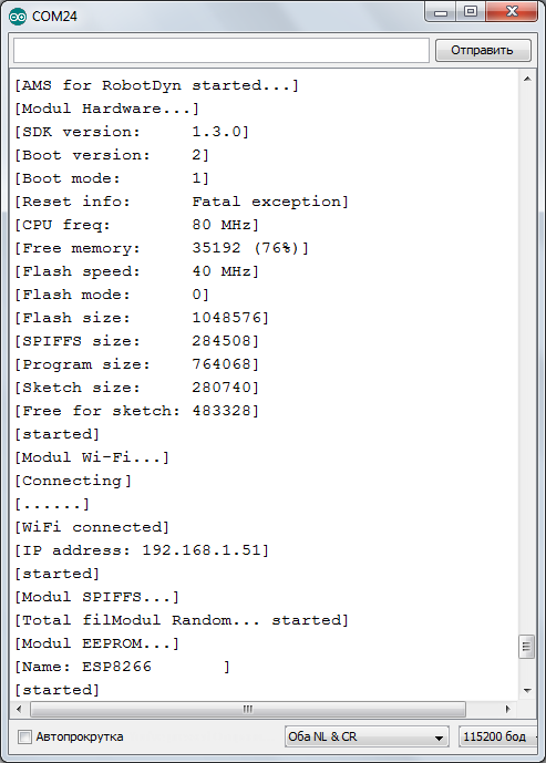
In the Mega 2560 Serial monitor, the output, data, and commands from the ESP part of the system look exactly the same as its own. In order to distinguish the output of the partner from the output of Mega, its data are enclosed in square quotes. In this case, you can see the ESP8266 restart and the AMS boot log in the Mega Serial monitor.
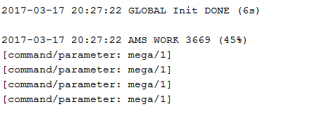
And the work log of the actual exchange of commands between the two parts of the system via the Serial interface. You can see the output of ESP8266 with information on decoding data on the state of Megi in the Serial interface of Mega itself, enclosed in square quotes.
Beauty in the interface
Now a little about how it all looks in the interface of the Arduino Mega Server. To begin with, I will provide screenshots of both parts of the system in operation.
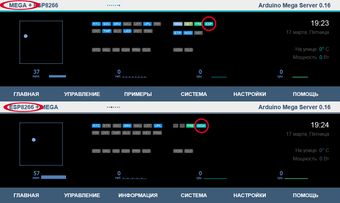
Ellipses are circled with inscriptions identifying the controller and the part of the system you are working with at the moment. Circles are circled with indicators that show the status of the partner. At the moment, everything is in order, both parts of the system work normally and interact normally with each other via the internal interface. If something goes wrong, then you will know about it in a maximum of 8 seconds.
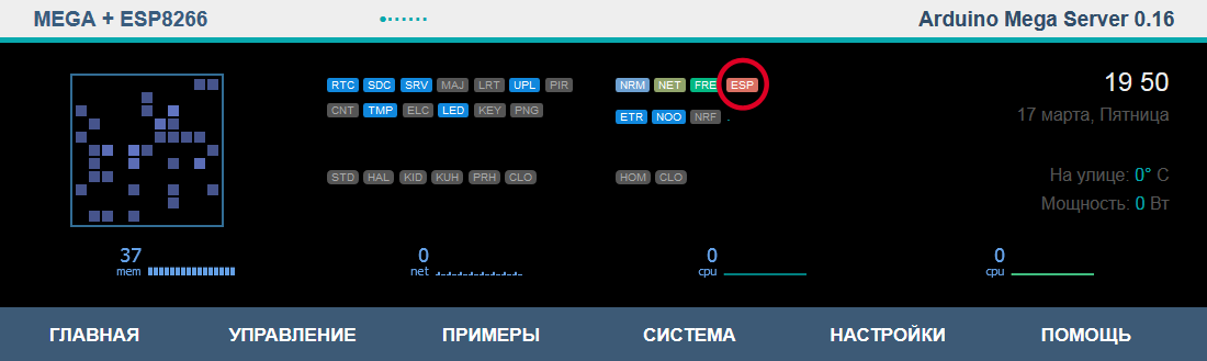
Something went wrong. ESP8266 received an update of the firmware through the air and the Mega-part of the system recorded the moment of its reboot. After a few seconds, the work of the ESP-part of the system will resume and the indicator will turn off red.
For convenience, when you hover the mouse cursor over the partner status indicator, a hint appears and you can click on it and the interface of the second part of the system opens in a separate window, in this case the ESP part. This is done for convenience, you can at any time with one click open the interface of the second part of the system.

Project Ideas
Now a little about what can be done from all this, possessing a bit of imagination. The usual fee, completely discreet at first glance, allows you to do a lot of very unusual and interesting things. This is especially true combination with the Arduino Mega Server.
So, the first thing that comes to mind:
Forwarding data from sensors between controllers. In both directions and in unlimited quantities. This is one system that has the virtues of both its parts, and the possibilities do not just add up, but what is called the synergistic effect is observed.
Bridge between interfaces. The Arduino Mega Server can work with multiple interfaces and this system allows you to arbitrarily route data and commands between any connected wired and wireless interfaces.
Work on the same network when Mega via Ethernet Shield, and ESP8266 via Wi-Fi communicate with wired and wireless devices on the same network.
Work in different networks when Mega is connected to a wired Ethernet, and ESP8266 via Wi-Fi to another network and the system routes commands and data from one network to another.
The output of one part of the system in the interface of the other. Via Ethernet using standard web-based methods or via internal Serial connection.
Debugging One part of the system can act as a debugger and tester of another part of the system according to your program.
Watchdog timer. Each controller can act as a kind of watchdog with respect to the other.
Logging failures. Each controller can log the work of its partner, compile statistics and report on alarming situations.
Database for ESP8266. With this system, you can organize something like a SQL database on Mega for ESP8266. ESP does its job, and Mega serves as a data storage system (up to 32 GB).
Flashing each other. The controllers can dynamically reflash each other in accordance with the established logic or upon the arrival of an external control command.
Connecting modules. Controllers can connect various peripherals that have problems connecting to any one part of the system.
And so on and so forth, I think an inquisitive reader will be able to independently invent many equally interesting ways of using this system.
Conclusion
In my opinion, this is a very interesting decision and we have to say to the company RobotDyn thank you very much for such an interesting fee . I, at least, say this quite sincerely.
Download the Arduino Mega Server distribution kit for RobotDyn Mega + ESP8266 and see for yourself that everything written here is correct, you can on the official website of the Arduino Mega Server project in the download section.
Source: https://habr.com/ru/post/402429/
All Articles