8-kilowatt 4-channel AC switch with consumption measurement. Part 1
To automate a large house, there was the task of turning on / off powerful loads - pool pumps, boilers, and even guest rooms as a whole (when nobody lives in them), and I also wanted to know the amount of energy they consumed. But there were no ready-made devices with the necessary characteristics (and even close to them). I had to invent myself. The first version was not very serviceable, but it showed that with a bit of work it would turn out to be a completely finished device.
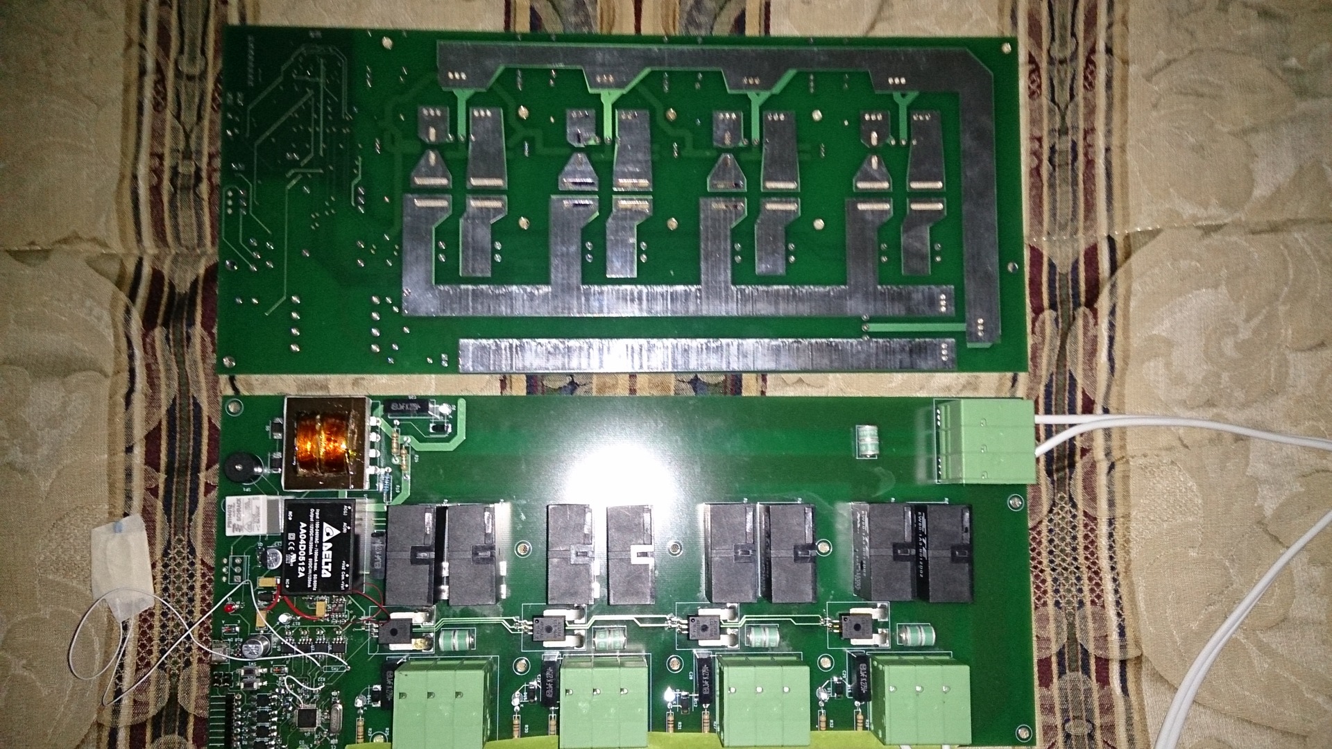
I admit honestly, I have practically no experience in creating powerful AC devices. Therefore, when developing this device, I tried to reinsure myself to the maximum - lightning arresters, wide tracks designed for soldering powerful copper buses, shielding in the intermediate layers of the board. In the first version, it was not without excesses and errors (for example, in the datasheet on the Voltage output 1 and Vout1 power module - they were not the same, so I had to cut the tracks, and I simply didn’t split the microUSB connector, so the port wasn’t works).
For switching, 80-amp bistable EW80 relays were selected. I must say, the choice is not very good - the case is leaky and in local conditions, high humidity may be unsuitable. Unfortunately, the choice of powerful bistable relays from available suppliers is not too large, so you have to either fill each relay separately with a sealant, or the entire case. As control keys, I took the ADP3624 MOSFET drivers at hand (one for each pair of relays), allowing to apply voltage to the windings in both polarities and de-energize them after operation. Consumption is measured by the hall sensors ACS759-100, and the mains voltage is measured through a low-power transformer. The STM32F373CBT6 acts as an ADC and control microcontroller.
')
To simplify the connection of the finished device - the input voltage is applied to one connector, and 7x3mm copper buses, soldered over the boards' tracks, will be stretched to all switching channels. In conditions of possibly very long wires up to the load (many tens of meters) - it was decided to switch simultaneously both zero and phase in order to avoid problems with crosstalk, distortions and just for safety. Since the board is not designed to work without external protection devices (“plugs”, RCDs) - there are no safety elements on it, there are only lightning arresters for protection against high voltage pulses. On each channel there is an indicator LED, there is also an alarm signaling circuit (“squeaker” and a relay for 10 amps of external load), but their use has not yet been used in software.
The device is controlled via a serial port with galvanic isolation (theoretically, it is possible to use a USB port), with a simple protocol similar to that used in my dimmer. Later, I will replace it with MQTT-over-serial.
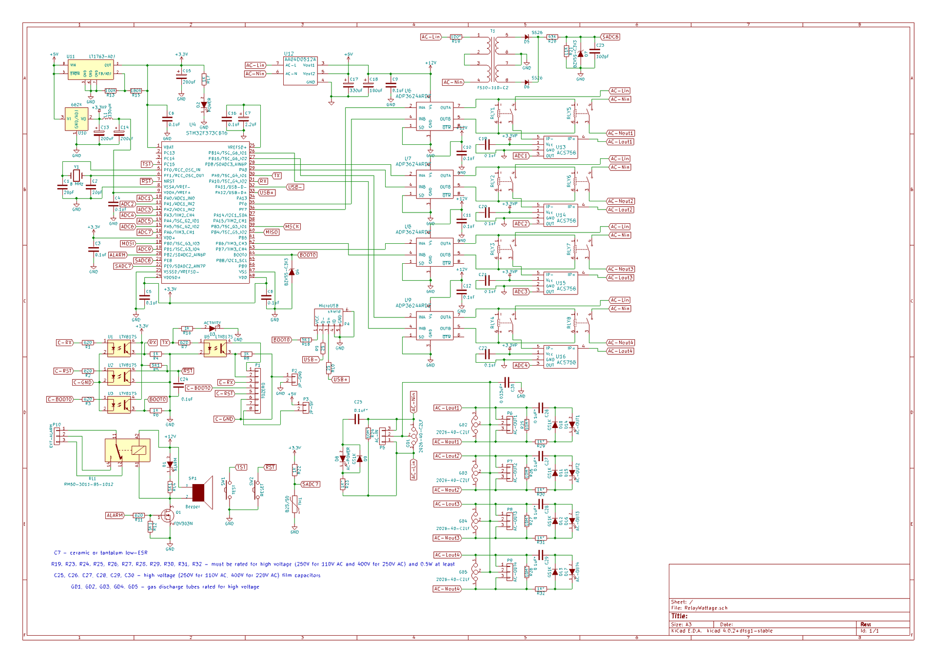
I must immediately say that the circuit turned out to be not very successful and in the next version it will change a little - the stability of 3.3 volts for power supply of current sensors and controller does not withstand any criticism, which leads to errors in power measurement of a couple of tens of watts (even with no load) Most likely, I will put stable sources of reference voltage 3.3v on each sensor separately. It is also possible to use a 16-bit ADC in the controller, but, unfortunately, its speed is not too high - now the current and voltage is measured about 5,000 times per second, which theoretically can be done with 16-bit, but I have not yet managed to achieve a stable It works with multiple channels via DMA.
The controller firmware once every ten seconds displays the data on the load consumption on each channel and the mains voltage, accepting commands to turn channels on and off. The software is very raw, it will also have to be redone and add various monitoring functions (for example, overvoltage in the network, overload, overheating of the board, etc.).
→ Githab code
I admit honestly, I have practically no experience in creating powerful AC devices. Therefore, when developing this device, I tried to reinsure myself to the maximum - lightning arresters, wide tracks designed for soldering powerful copper buses, shielding in the intermediate layers of the board. In the first version, it was not without excesses and errors (for example, in the datasheet on the Voltage output 1 and Vout1 power module - they were not the same, so I had to cut the tracks, and I simply didn’t split the microUSB connector, so the port wasn’t works).
For switching, 80-amp bistable EW80 relays were selected. I must say, the choice is not very good - the case is leaky and in local conditions, high humidity may be unsuitable. Unfortunately, the choice of powerful bistable relays from available suppliers is not too large, so you have to either fill each relay separately with a sealant, or the entire case. As control keys, I took the ADP3624 MOSFET drivers at hand (one for each pair of relays), allowing to apply voltage to the windings in both polarities and de-energize them after operation. Consumption is measured by the hall sensors ACS759-100, and the mains voltage is measured through a low-power transformer. The STM32F373CBT6 acts as an ADC and control microcontroller.
')
To simplify the connection of the finished device - the input voltage is applied to one connector, and 7x3mm copper buses, soldered over the boards' tracks, will be stretched to all switching channels. In conditions of possibly very long wires up to the load (many tens of meters) - it was decided to switch simultaneously both zero and phase in order to avoid problems with crosstalk, distortions and just for safety. Since the board is not designed to work without external protection devices (“plugs”, RCDs) - there are no safety elements on it, there are only lightning arresters for protection against high voltage pulses. On each channel there is an indicator LED, there is also an alarm signaling circuit (“squeaker” and a relay for 10 amps of external load), but their use has not yet been used in software.
The device is controlled via a serial port with galvanic isolation (theoretically, it is possible to use a USB port), with a simple protocol similar to that used in my dimmer. Later, I will replace it with MQTT-over-serial.
I must immediately say that the circuit turned out to be not very successful and in the next version it will change a little - the stability of 3.3 volts for power supply of current sensors and controller does not withstand any criticism, which leads to errors in power measurement of a couple of tens of watts (even with no load) Most likely, I will put stable sources of reference voltage 3.3v on each sensor separately. It is also possible to use a 16-bit ADC in the controller, but, unfortunately, its speed is not too high - now the current and voltage is measured about 5,000 times per second, which theoretically can be done with 16-bit, but I have not yet managed to achieve a stable It works with multiple channels via DMA.
The controller firmware once every ten seconds displays the data on the load consumption on each channel and the mains voltage, accepting commands to turn channels on and off. The software is very raw, it will also have to be redone and add various monitoring functions (for example, overvoltage in the network, overload, overheating of the board, etc.).
→ Githab code
Source: https://habr.com/ru/post/402375/
All Articles