Designing a switching power supply with active CMC. Episode II
In my previous article, I talked about designing a switching power supply, showed it to the circuitry and board design. I stopped at the fact that the boards for the project were ordered at the factory, I received them and you can proceed to the assembly of the device.
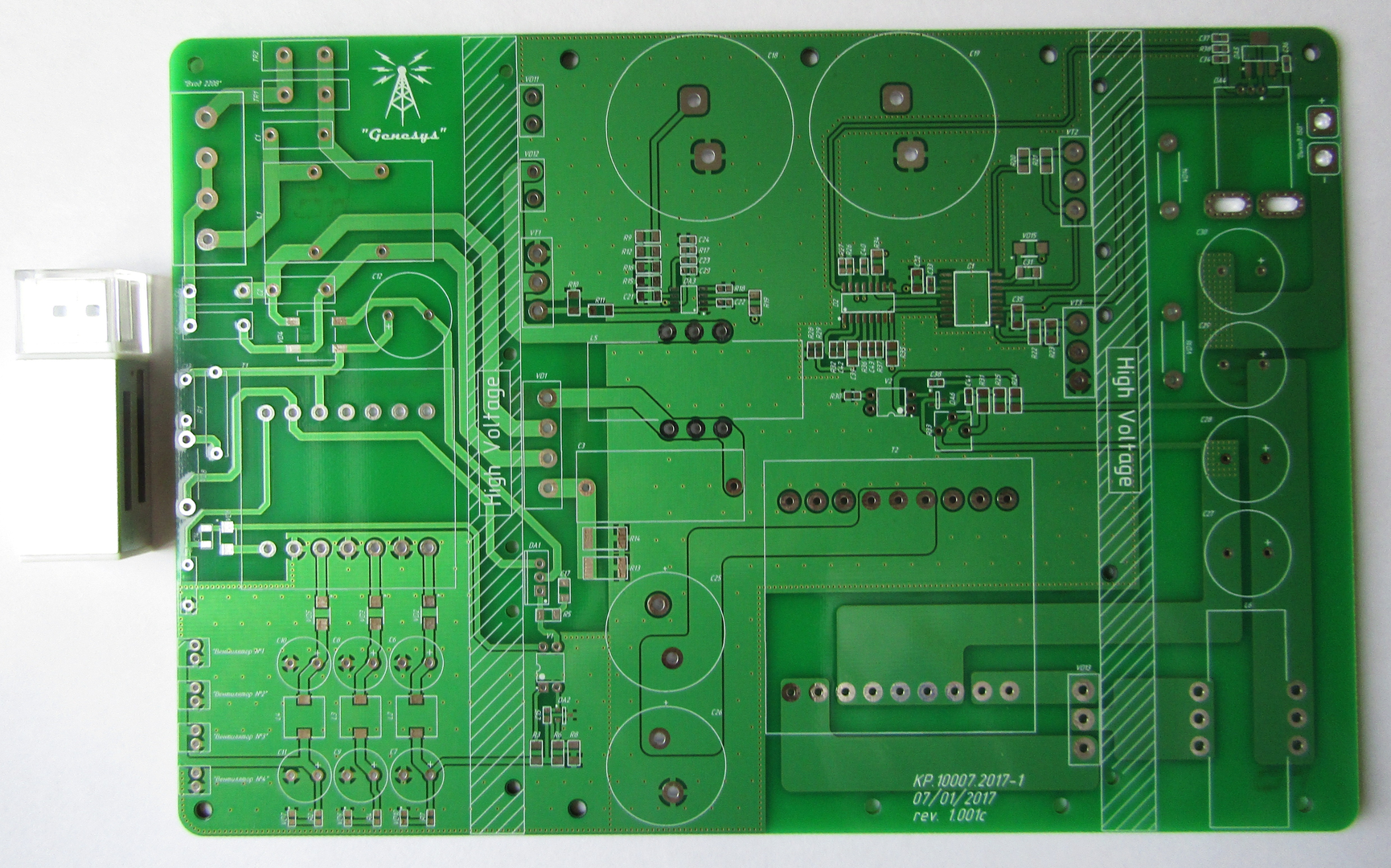
Figure 1 - PCB view (top)
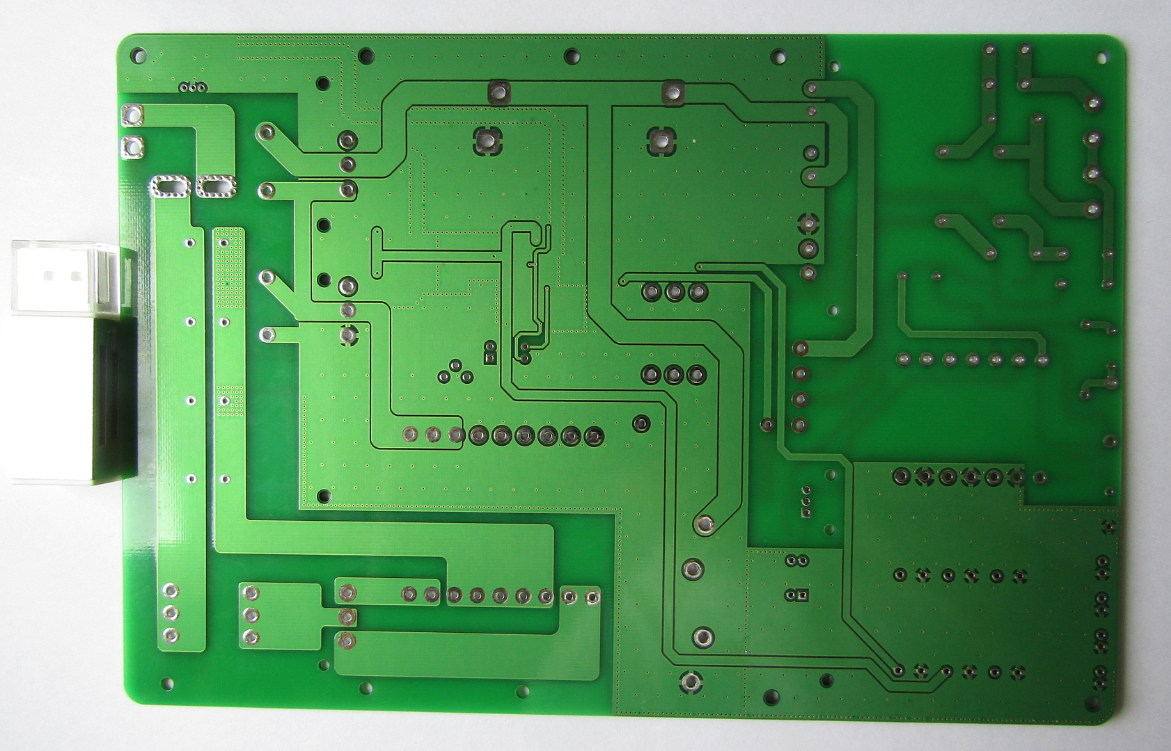
Figure 2 - PCB view (bottom)
')
In this article I will only talk about the input common-mode filter and a multi-channel power supply for powering the PWM controllers and the cooling system. It’s not convenient to write large articles for a long time, so I decided to dose in small quantities, but a little more often.
You can familiarize yourself with the theoretical part in the previous article, but now I will remind you that this is a flyback converter, which has 3 galvanically isolated channels of 15V each with a rated current of 1A. This is more than enough to power the controllers. In reality, it would be possible to restrict 200-300 mA per channel, but only ETD34 was at hand and it was decided to do it with a margin — it wouldn't be superfluous.
At first, I wanted to mount SMD components at once in the oven, but such a path somewhat complicates debugging, so we first solder the components of the input group + all components for our flyback:
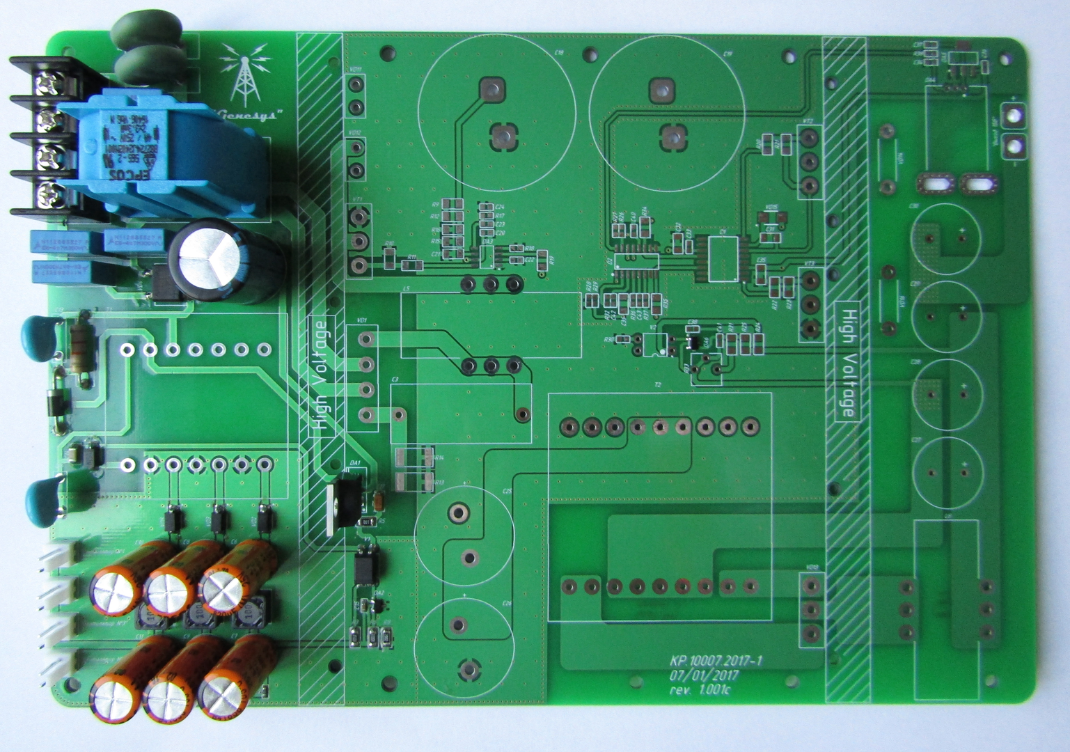
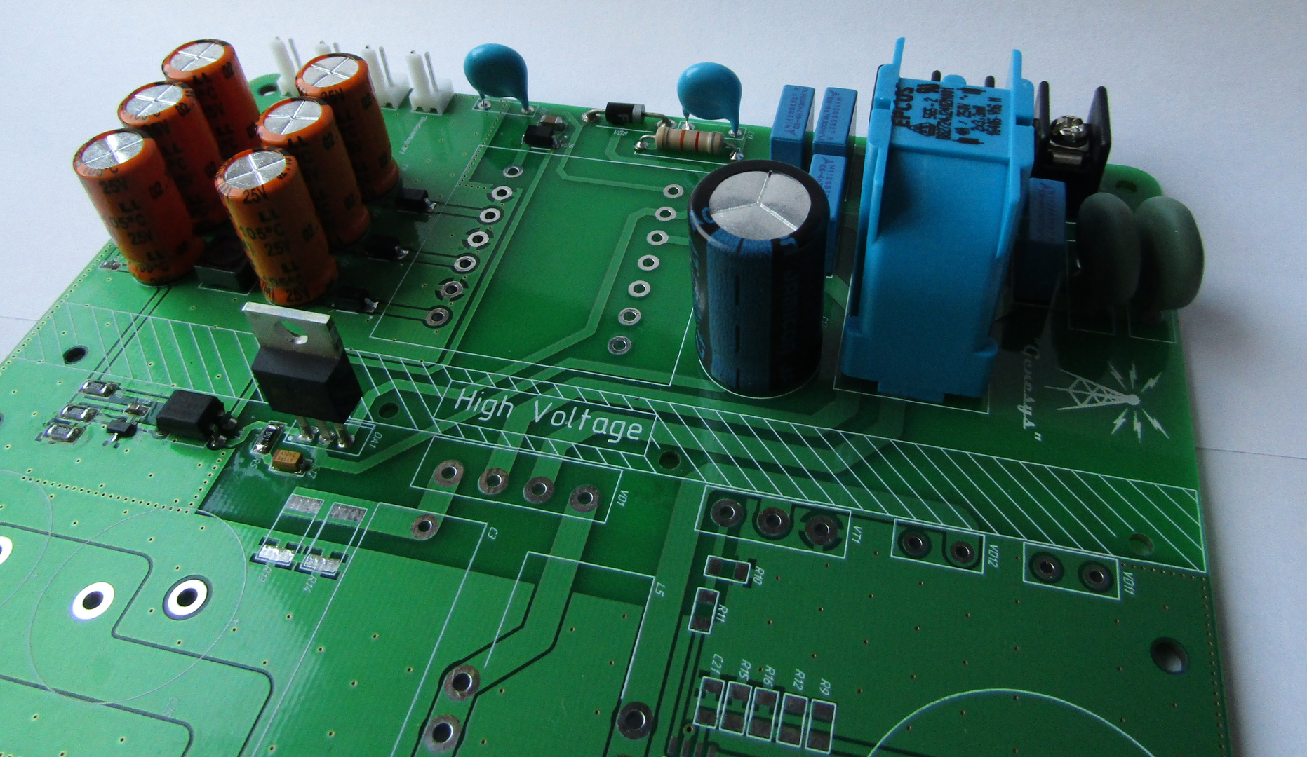
Figure 3 - The appearance of the board after installation of the components of the in-phase filter and its own power supply
There are no supernatural components here, but as you probably noticed, there is no transformer. Probably, 60-70% of the questions I get asked in the drugs are somehow related to the waste products, most often: "How to wind a transformer (choke)?" Therefore, the next section is devoted to the manufacture of a transformer.
There are two main problems because of which problems arise with the hatch products, this is the gap and the definition of the beginning of the windings . It is precisely these two aspects that can completely “hack” your entire converter on the root, so for more on them.
1) If you look at any power supply circuit where there is a transformer, then you can see a “point” near one of the ends of the winding - this is the way to designate its beginning. It looks like this:
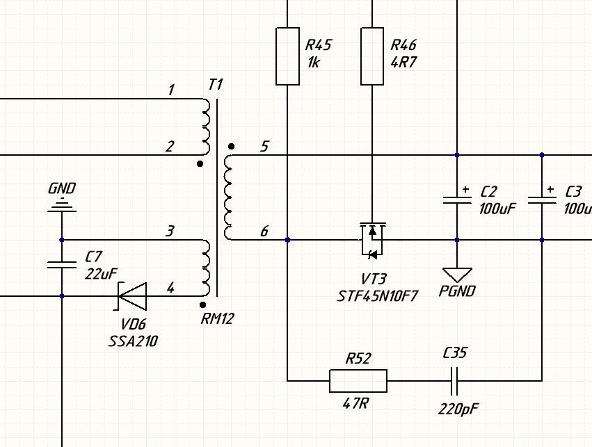
Figure 4 - Symbols of the transformer
In single-ended converters, this aspect plays a key role, due to the fact that the magnetic flux is a vector quantity, which means its direction is just as important as its value. Therefore, when you start to wind the transformer, be sure to mark from which output you start to wind, it will be that very point - the beginning. Also, all windings should be wound in one direction, this is not quite so, but it is in the process of winding that everything is wound in one direction . In the case of the flyback, when you unsolder everything according to the “beginning of the windings”, it turns out that the flow in the primary winding has the opposite direction, which is why the energy transfer goes on the reverse stroke / course. Hence the name of this topology. Compliance with the marks “beginning of the winding” and winding in one direction during the manufacturing process will not allow you to get confused.
2) Clearance ... In push-pull converters, it is not (not always), so this type of transformers is practically not affected, but the moment is relevant when manufacturing chokes and transformers for single-ended converters.
If in a simple way - the gap does not allow your core to get enough, that is, the larger the gap, the greater the amount(power) of energy you can pump through it. That is, by increasing the gap to infinity, we can increase the power of the transformer to infinity, but there is one limitation ...
As the gap increases, the inductance of the winding decreases. That is, in order to obtain the required inductance value, we will have to wind a greater number of turns, while the number of turns is already limited by the size of the core. Actually, therefore, it is impossible to get that same “infinitepower! power".
As for the chokes (by the way, the transformer of the single tactics is also chokes) - if it is made of ferrite, for example, N87, then the gap is obligatory! Otherwise, the core will be saturated and the power of the converter will drop to almost zero. That is why people often gather BP and run at idle, they are happy that it works, but under load it “shuts up” - most likely in such cases it’s a gap.
a) Select the appropriate set, I use ETD34. It consists of a frame, 2 parts of the core with already factory gaps of 0.2 mm and fixing brackets. I also use “special scotch tape” as insulation, its charm is that it is thin and durable, which means it practically does not take place in the transformer window.
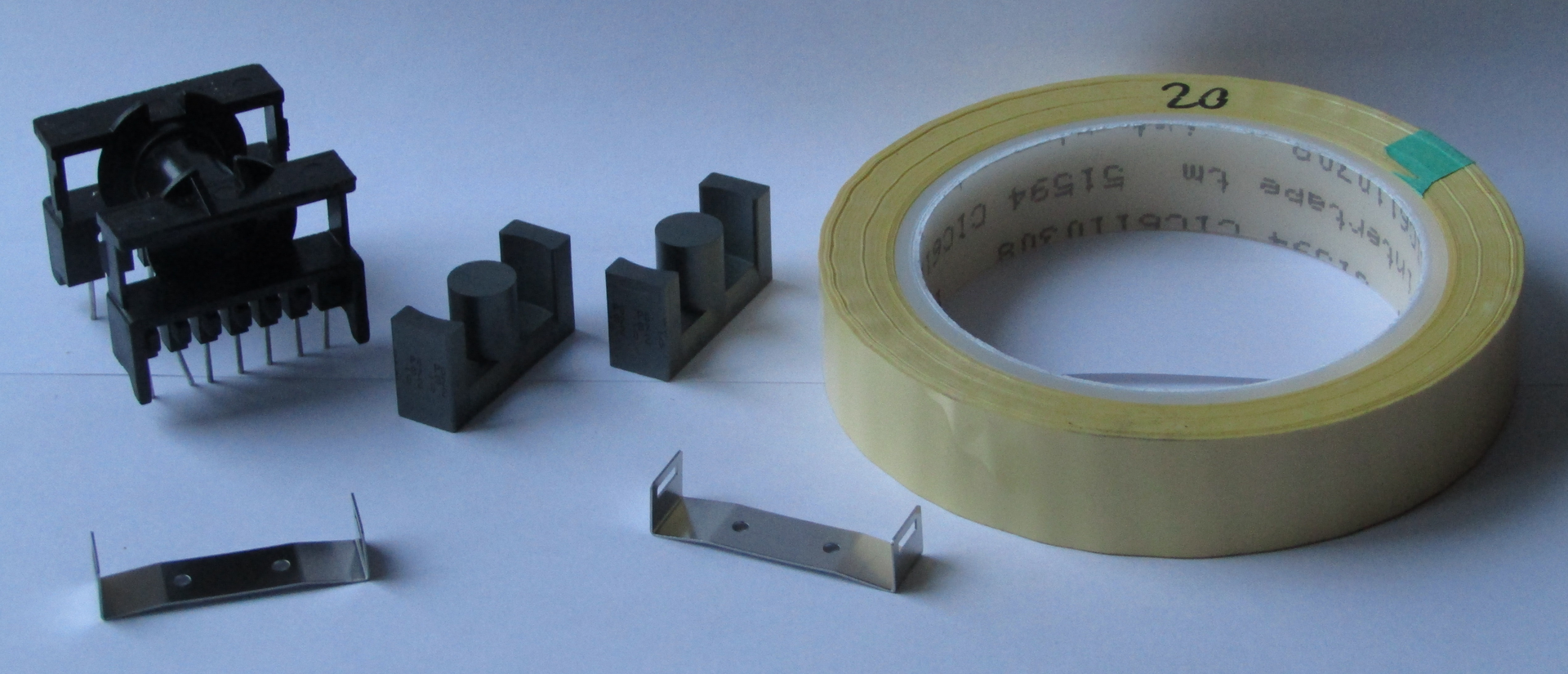
Figure 5 - Kit for the manufacture of a transformer
You also need a copper lacquered wire, preferably winding. What good is “winding” - it is subjected to annealing after broaching and therefore softer, and therefore easier to wind. On small transformers it is not very critical, but for 500+ watts, hands will say thanks for that, although it is certainly 10-15% more expensive, but you decide. I use annealed with a diameter of 0.335 mm.
b) We start the process of winding. I advise you to start winding with the thinnest winding: in the down-converters this is the primary winding, for raising it is the secondary. This will allow you to wind neatly, tightly the most complex winding, because To do this on top of the “fat and curve” will be quite problematic. Again, the low power will forgive you the neglect of this advice, but at the power of 500+ watts you will be very sad.
After winding each layer of the primary winding (I have it in 3 layers), we insulate 1-2 layers with insulating tape. As the entire winding is wound, we unsolder it and isolate the winding in 3-4 layers, this is already interwinding insulation - it is the most important and the isolation voltage of the transformer depends on it.
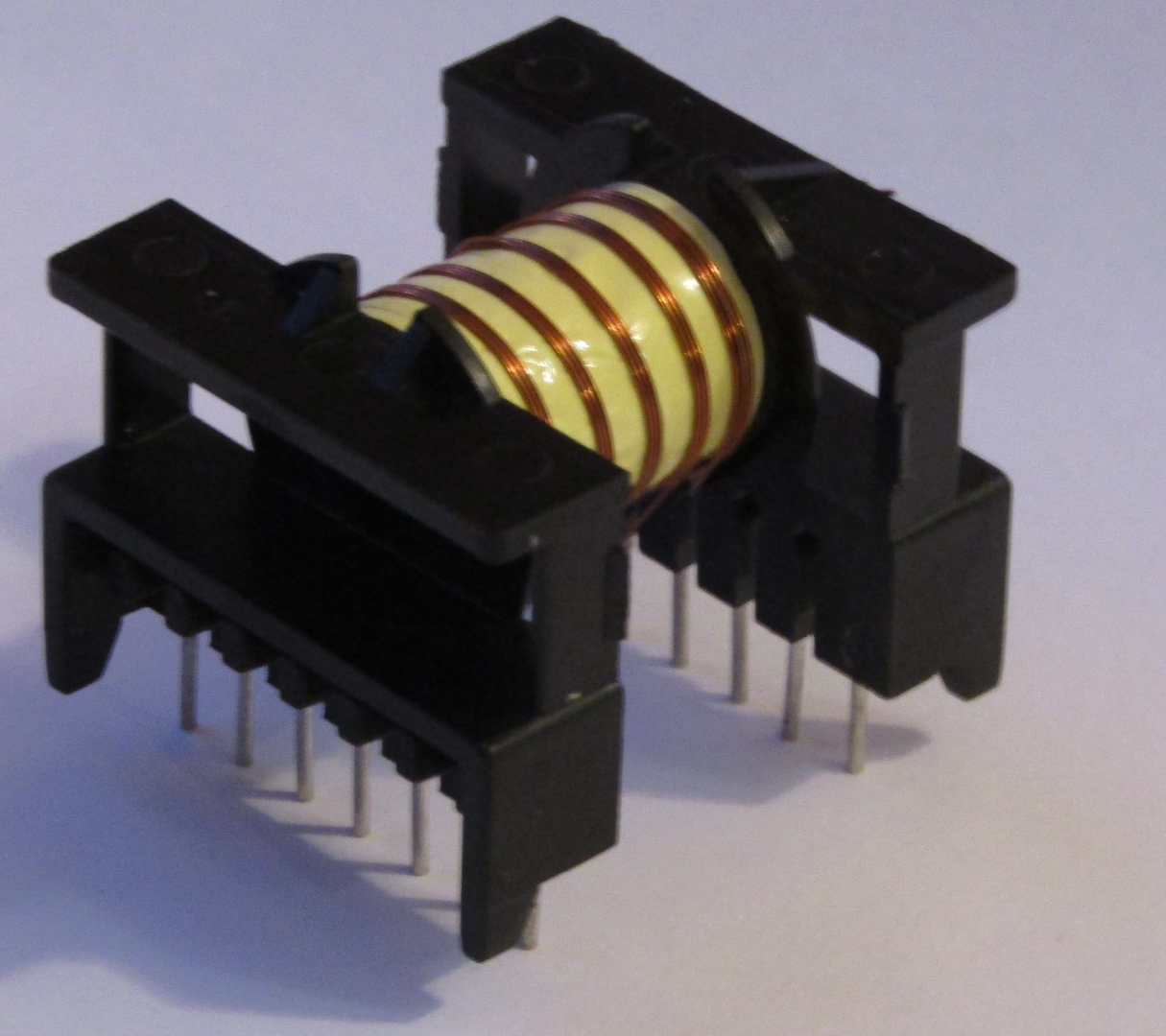
Figure 6 - Type of transformer after winding the primary winding and the power winding
c) Next, we wind the remaining windings, better in order of increasing thethickness of the wire section. The principles of insulation are the same as on the primary winding. After all windings are wound, if space permits, we pass the final 5-6 turns additionally with tape.
I also recommend, after winding all the windings and final isolation, “punch” with varnish, for example, Plastik-71. This will allow you not to worry about possible moisture, condensate, dust and other nastiness. Better in 2-3 passes, allowing the previous to dry. And it is better to do this only on the frame before assembling the transformer + do not forget to cover the findings from varnish.
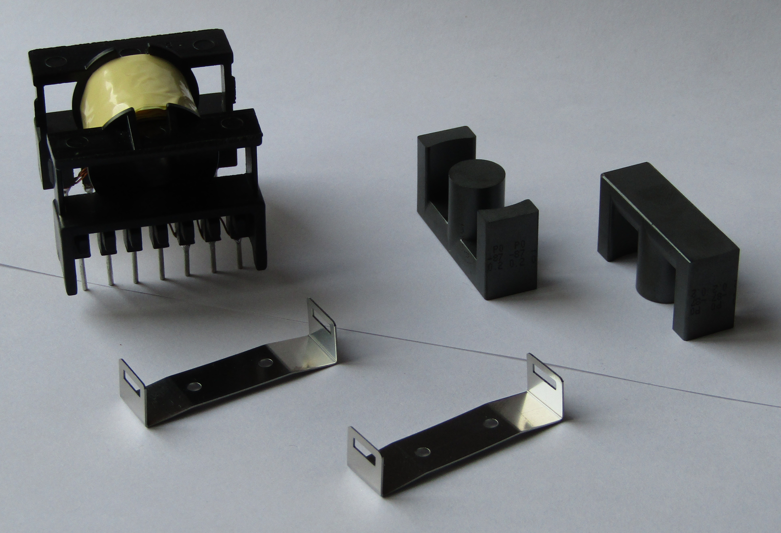
Figure 7 - Type of frame after winding and insulation of all windings
d) Now it remains to simply assemble the transformer. Themselves half of the core can be fixed with staples, and can be glued. The last operation is ideally performed with a special glue with the addition of dispersed ferrite powder, and this can be done with the usual moment. Only I strongly recommend gluing a thin layer - otherwise the gap will increase and the inductance will decrease. I also advise you not to spread the average “leg” with glue, this completely deprives you of the chance to disassemble it if necessary.
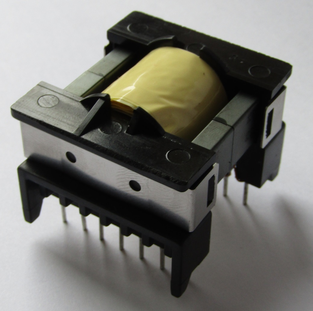
Figure 8 - Type of transformer after assembly
In general, it remains only to solder the transformer on our board and the assembly of this node will be completed, it will only remain to check the performance.
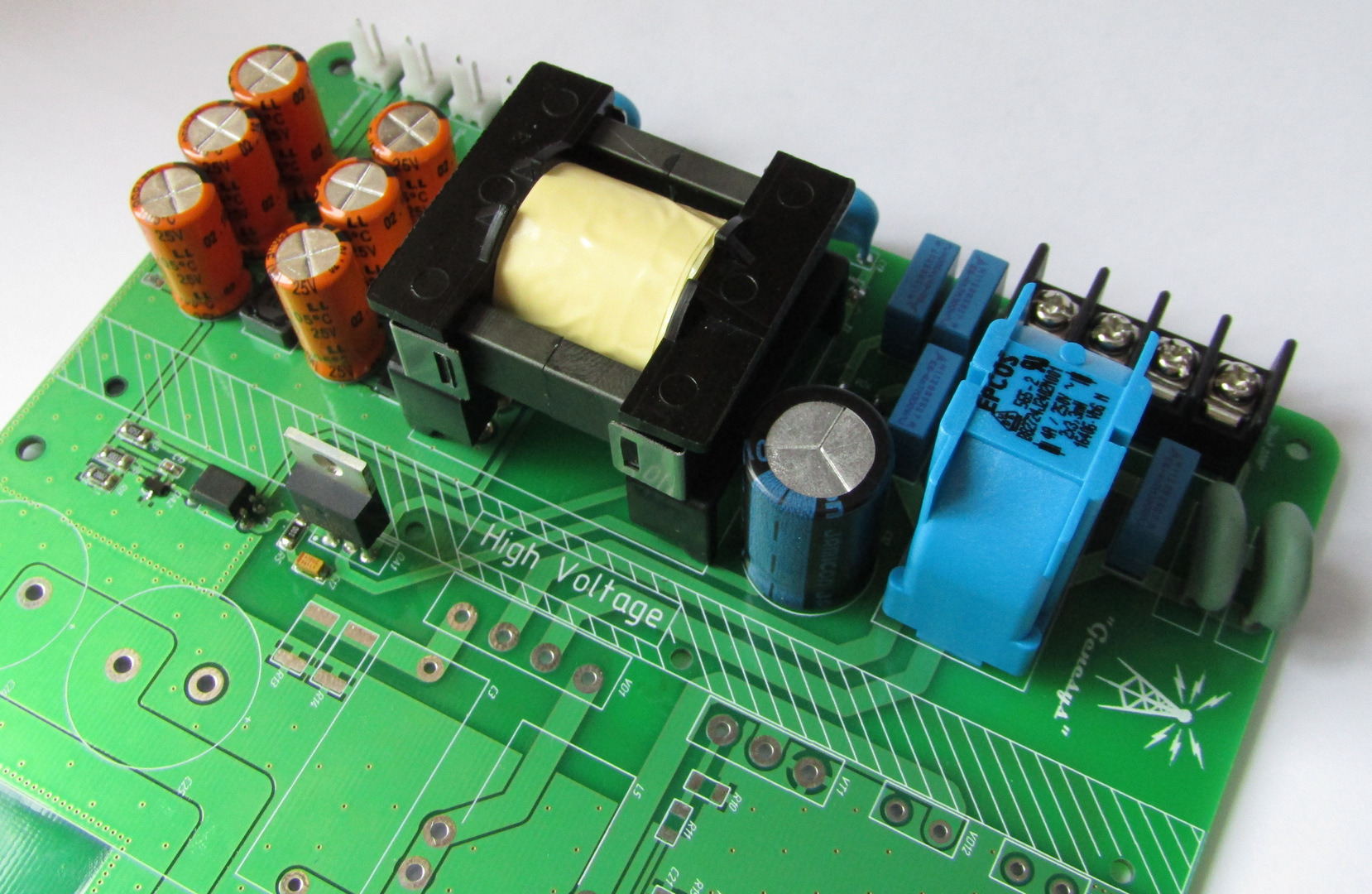
Figure 9 - The appearance of the board after the installation of the input circuits and power supply units of their own needs
It is always scary to turn on the equipment in the network, especially if it is collected without experience, it is scary that it will bang or shock it - only fools are not afraid. Therefore, if you decide to assemble a device from an article or any other with mains supply, then the first switching on after assembly is better done with the help of special tools. There are several options:
1) Test bench or laboratory source with an output of 0-400V just for such cases. The price tag on them starts from about 80-120 thousand rubles, therefore, for certain reasons, not everyone can afford it at home, and you are unlikely to collect 2-3 new units a week so that such equipment is relevant. So do you need it?
2) Switching on via transformer 1: 1 + electronic fuse. This method is cheap, which means it is available to everyone. The transformer will untie the device and you from the network, and the fuse will not allow the unit to puff. This collective farm equipment for 1000 rubles is clearly more accessible than the first item, and most importantly for the fans, it’s no worse.
3) Probably a classic of the genre - we unsolder a fuse and instead we solder a 230V 60W lamp. Only incandescent lamp! Such a replacement will not allow the unit to burn. If everything is good, then without a load, when the lamp is turned on, the bulb will light up and go out: it will flash, because charge input capacity. If it caught fire and does not go out, then somewhere short circuit - turn off and check the circuit.
Just do not forget to discharge the high-voltage capacitors! A battery of two 470 microfarads of Conder discharged into your hand (especially if slightly wet) with a 90% probability will ensure you travel with flashing lights to the nearest hospital or morgue. A constant current is much more dangerous than a break, it is not in vain that they put a constant on an electric chair.
4) An option forreal professionals gibberish - just put it in the socket. If there is a short circuit in the circuit or some other jamb, then on the condition that a good electrician did the wiring to you, the transistor will knock out the automata and the transistor will burn, if the unit is not made by a very competent person, then the unit will burn and melt and it’s not a fact that the machine will knock it out. Therefore, I strongly advise paragraph 2.
Now actually to the test. I use an incandescent bulb at 12V and 10W. Its current is about 900-1100 mA, this is enough to test our unit. In fact, I’ll just hang as a load on the channel and see what the output voltage is and how distorted they are, because all stabilized by one of the 3 windings.
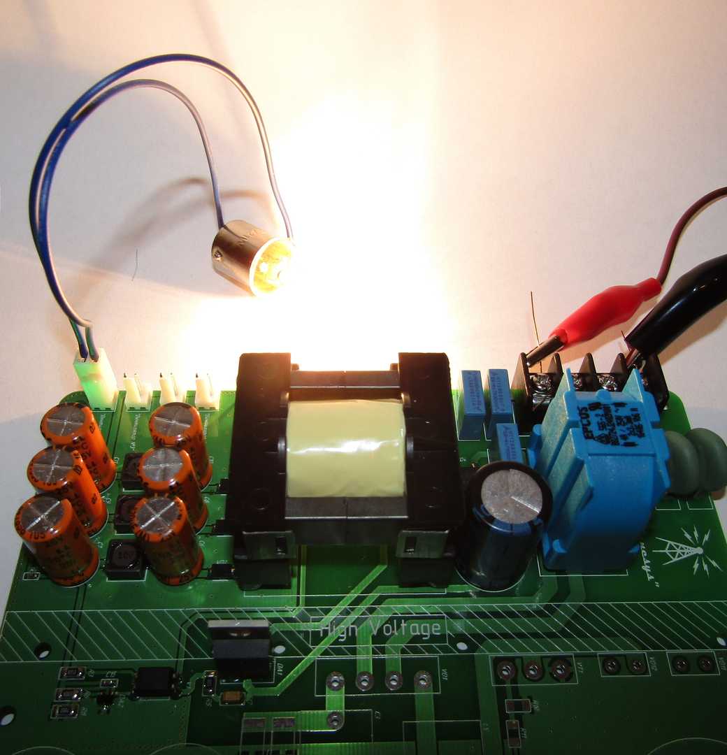
Figure 10 - Type of operation of auxiliary power units under nominal channel load
In the next part, I will show the results of the assembly and debugging of the CMC, as well as share my results under the calculation of the output capacitance. Very interesting results were obtained there, especially when replacing electrolytes with a film, which will be the story.
The format of further articles will be the same - small narration of the results, some comments and "tips" for beginners.
One more thing - I will not read the comments, alas and ah ... They take a lot of time, and the benefits of them are a little less than zero, because Reading the tips and opinions of experts ala "yes, two ATHs should be stuck together and it will be cool" - theMinistry of Health warns cause brain cancer.
If you really want to personally ask me something, advise, discuss a question, then welcome to PM.
Hope to see you soon! The part on KKM is already written in "Drafts" and I will try to bring it as quickly as possible to a logical conclusion and publish it for your review.
Why the article will not be big
Unfortunately, I managed to break the ban for some of the comments, as a result, the “drafts” were not available, including for this article. To rewrite everything from scratch neither time nor great desire is present. Therefore, I will show the main stages, photographs, especially as the previous article showed - only great specialists read and comment, so my explanations are hardly necessary for someone.
Actually, the first unit was assembled and left for my friend, the second one I already collect for my beloved one - he will appear in this article.
Actually, the first unit was assembled and left for my friend, the second one I already collect for my beloved one - he will appear in this article.
Figure 1 - PCB view (top)
Figure 2 - PCB view (bottom)
')
Installation of the in-phase filter and auxiliary power supply unit
In this article I will only talk about the input common-mode filter and a multi-channel power supply for powering the PWM controllers and the cooling system. It’s not convenient to write large articles for a long time, so I decided to dose in small quantities, but a little more often.
You can familiarize yourself with the theoretical part in the previous article, but now I will remind you that this is a flyback converter, which has 3 galvanically isolated channels of 15V each with a rated current of 1A. This is more than enough to power the controllers. In reality, it would be possible to restrict 200-300 mA per channel, but only ETD34 was at hand and it was decided to do it with a margin — it wouldn't be superfluous.
At first, I wanted to mount SMD components at once in the oven, but such a path somewhat complicates debugging, so we first solder the components of the input group + all components for our flyback:
Figure 3 - The appearance of the board after installation of the components of the in-phase filter and its own power supply
There are no supernatural components here, but as you probably noticed, there is no transformer. Probably, 60-70% of the questions I get asked in the drugs are somehow related to the waste products, most often: "How to wind a transformer (choke)?" Therefore, the next section is devoted to the manufacture of a transformer.
Transformer manufacturing
There are two main problems because of which problems arise with the hatch products, this is the gap and the definition of the beginning of the windings . It is precisely these two aspects that can completely “hack” your entire converter on the root, so for more on them.
1) If you look at any power supply circuit where there is a transformer, then you can see a “point” near one of the ends of the winding - this is the way to designate its beginning. It looks like this:
Figure 4 - Symbols of the transformer
In single-ended converters, this aspect plays a key role, due to the fact that the magnetic flux is a vector quantity, which means its direction is just as important as its value. Therefore, when you start to wind the transformer, be sure to mark from which output you start to wind, it will be that very point - the beginning. Also, all windings should be wound in one direction, this is not quite so, but it is in the process of winding that everything is wound in one direction . In the case of the flyback, when you unsolder everything according to the “beginning of the windings”, it turns out that the flow in the primary winding has the opposite direction, which is why the energy transfer goes on the reverse stroke / course. Hence the name of this topology. Compliance with the marks “beginning of the winding” and winding in one direction during the manufacturing process will not allow you to get confused.
2) Clearance ... In push-pull converters, it is not (not always), so this type of transformers is practically not affected, but the moment is relevant when manufacturing chokes and transformers for single-ended converters.
If in a simple way - the gap does not allow your core to get enough, that is, the larger the gap, the greater the amount
As the gap increases, the inductance of the winding decreases. That is, in order to obtain the required inductance value, we will have to wind a greater number of turns, while the number of turns is already limited by the size of the core. Actually, therefore, it is impossible to get that same “infinite
As for the chokes (by the way, the transformer of the single tactics is also chokes) - if it is made of ferrite, for example, N87, then the gap is obligatory! Otherwise, the core will be saturated and the power of the converter will drop to almost zero. That is why people often gather BP and run at idle, they are happy that it works, but under load it “shuts up” - most likely in such cases it’s a gap.
We now turn to the manufacturing process:
a) Select the appropriate set, I use ETD34. It consists of a frame, 2 parts of the core with already factory gaps of 0.2 mm and fixing brackets. I also use “special scotch tape” as insulation, its charm is that it is thin and durable, which means it practically does not take place in the transformer window.
Figure 5 - Kit for the manufacture of a transformer
You also need a copper lacquered wire, preferably winding. What good is “winding” - it is subjected to annealing after broaching and therefore softer, and therefore easier to wind. On small transformers it is not very critical, but for 500+ watts, hands will say thanks for that, although it is certainly 10-15% more expensive, but you decide. I use annealed with a diameter of 0.335 mm.
b) We start the process of winding. I advise you to start winding with the thinnest winding: in the down-converters this is the primary winding, for raising it is the secondary. This will allow you to wind neatly, tightly the most complex winding, because To do this on top of the “fat and curve” will be quite problematic. Again, the low power will forgive you the neglect of this advice, but at the power of 500+ watts you will be very sad.
After winding each layer of the primary winding (I have it in 3 layers), we insulate 1-2 layers with insulating tape. As the entire winding is wound, we unsolder it and isolate the winding in 3-4 layers, this is already interwinding insulation - it is the most important and the isolation voltage of the transformer depends on it.
Figure 6 - Type of transformer after winding the primary winding and the power winding
c) Next, we wind the remaining windings, better in order of increasing the
I also recommend, after winding all the windings and final isolation, “punch” with varnish, for example, Plastik-71. This will allow you not to worry about possible moisture, condensate, dust and other nastiness. Better in 2-3 passes, allowing the previous to dry. And it is better to do this only on the frame before assembling the transformer + do not forget to cover the findings from varnish.
Figure 7 - Type of frame after winding and insulation of all windings
d) Now it remains to simply assemble the transformer. Themselves half of the core can be fixed with staples, and can be glued. The last operation is ideally performed with a special glue with the addition of dispersed ferrite powder, and this can be done with the usual moment. Only I strongly recommend gluing a thin layer - otherwise the gap will increase and the inductance will decrease. I also advise you not to spread the average “leg” with glue, this completely deprives you of the chance to disassemble it if necessary.
Figure 8 - Type of transformer after assembly
Final build
In general, it remains only to solder the transformer on our board and the assembly of this node will be completed, it will only remain to check the performance.
Figure 9 - The appearance of the board after the installation of the input circuits and power supply units of their own needs
First power on and performance test
It is always scary to turn on the equipment in the network, especially if it is collected without experience, it is scary that it will bang or shock it - only fools are not afraid. Therefore, if you decide to assemble a device from an article or any other with mains supply, then the first switching on after assembly is better done with the help of special tools. There are several options:
1) Test bench or laboratory source with an output of 0-400V just for such cases. The price tag on them starts from about 80-120 thousand rubles, therefore, for certain reasons, not everyone can afford it at home, and you are unlikely to collect 2-3 new units a week so that such equipment is relevant. So do you need it?
2) Switching on via transformer 1: 1 + electronic fuse. This method is cheap, which means it is available to everyone. The transformer will untie the device and you from the network, and the fuse will not allow the unit to puff. This collective farm equipment for 1000 rubles is clearly more accessible than the first item, and most importantly for the fans, it’s no worse.
3) Probably a classic of the genre - we unsolder a fuse and instead we solder a 230V 60W lamp. Only incandescent lamp! Such a replacement will not allow the unit to burn. If everything is good, then without a load, when the lamp is turned on, the bulb will light up and go out: it will flash, because charge input capacity. If it caught fire and does not go out, then somewhere short circuit - turn off and check the circuit.
Just do not forget to discharge the high-voltage capacitors! A battery of two 470 microfarads of Conder discharged into your hand (especially if slightly wet) with a 90% probability will ensure you travel with flashing lights to the nearest hospital or morgue. A constant current is much more dangerous than a break, it is not in vain that they put a constant on an electric chair.
4) An option for
Now actually to the test. I use an incandescent bulb at 12V and 10W. Its current is about 900-1100 mA, this is enough to test our unit. In fact, I’ll just hang as a load on the channel and see what the output voltage is and how distorted they are, because all stabilized by one of the 3 windings.
Figure 10 - Type of operation of auxiliary power units under nominal channel load
Conclusion
In the next part, I will show the results of the assembly and debugging of the CMC, as well as share my results under the calculation of the output capacitance. Very interesting results were obtained there, especially when replacing electrolytes with a film, which will be the story.
The format of further articles will be the same - small narration of the results, some comments and "tips" for beginners.
One more thing - I will not read the comments, alas and ah ... They take a lot of time, and the benefits of them are a little less than zero, because Reading the tips and opinions of experts ala "yes, two ATHs should be stuck together and it will be cool" - the
If you really want to personally ask me something, advise, discuss a question, then welcome to PM.
Hope to see you soon! The part on KKM is already written in "Drafts" and I will try to bring it as quickly as possible to a logical conclusion and publish it for your review.
Source: https://habr.com/ru/post/402303/
All Articles