Powerful four-channel dimmer for LEDs
In this article I will talk about the project of a powerful four-channel dimmer for LED strips and lamps (up to 200 watts total power, 50..100 watts per channel) with high frequency PWM regulation (1 kilohertz with a color depth of 10 bits), for high-quality lighting . In addition, it has a light sensor input, feedback functions (outputting information to the controller on the input supply voltage, the voltage at the measuring inputs, and so on), and even galvanic isolation of the serial control port.
It so happened that I decided to change my profile and tackle microcontrollers and automation tightly, and after a few months I received a tempting offer to make a “smart home” in the Dominican Republic, and such that almost all aspects of the life of a fairly large villa of three large buildings, from lighting and climate, to garden robots and irrigation systems. Since I was tired of snow and frost for a long time, it was impossible to reject such a proposal, especially since they helped me with the move and adaptation.
Of course, one of the most important tasks is to control the lighting, both in a multitude of rooms and outside. In order to save expensive electricity here - almost everywhere will be used LED strips and 12-volt lamps, which need to be controlled using dimmers. Existing dimmer models were not very satisfactory in all respects (high enough control frequency, for the absence of flicker; power, for controlling bright long stripes or lamps / spotlights; closed exchange protocols, and so on). So I decided to make my own dimmer.
')
A very sensitive issue at the design stage was the choice of obtaining low-voltage power from 110 volts AC. Even an exotic version with a transformerless step-down was immediately considered up to 12 volts, but due to electrical and fire safety considerations was rejected. Ready-made power supplies 110-> 12 turned out to be not that expensive ($ 20 for 120 watts and $ 40 for 200), although they are quite large. But, fortunately, there was a lot of space for equipment placement, so I settled on this option.
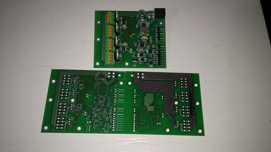
The circuit turned out to be relatively simple (except for the galvanic decoupling node of the serial port on four optocouplers) - the STM32F030F4P6 microcontroller, two ADP3624 MOSFET drivers and IRLB8748 key transistors selected with a large margin (with a load of 100 watts per channel - they were barely warm) , plus a ready-made Chinese module pulsed step-down at 3.3 volts. The selected drivers allow you to control at frequencies up to megahertz, which gives the frequency of the output voltage in kilohertz, with a PWM step of one microsecond. In practice, even a PWM mode of eight kilohertz and 125 nanosecond increments was tested, but in practice such a high adjustment frequency threatens with some instability at the output — transistors may simply not have time to close so quickly and the quality of adjustment will “float”.

The layout of the board for such large currents was a rather difficult challenge for me, I had never encountered such tasks before. It was decided to make as wide as possible (a conductor with a minimum width of 10 mm on a layer of 70 μm copper), and where it is impossible to use the second layer, merging them with a large number of vias. I removed the mask from the high-loaded conductors so that, if necessary, it was possible to put a copper bus on top (but this was not needed, even with a maximum load of 200 watts - the board heats up to only 40 degrees in a closed case).
The exchange protocol, due to the lack of flash memory, was chosen extremely simple, the commands are transmitted line by line, in the form of text "0: 512" (zero channel, PWM 512), the output data is transmitted in the same way (power supply, data from the first photoresistor, data from the second photoresistor, input voltage on the ADC3 input, input voltage on the ADC5 input, controller supply voltage, chip temperature). It would be more correct to use the MQTT protocol, but I was afraid that it would not fit into the flash (the kilobyte of free space remained out of 16).
→ Githab Source Code
The dimmer is stitched through the same control port (you need to feed the unit to the 4th pin, then the pulse to the 5th, after which the microcontroller can be loaded using the standard serial protocol STM32. To control the dimmer already flashed, three wires are enough, + 3.3 / + 5V on the first pin, data on the third, on the sixth - the ground. The settings of the control port in the firmware are 38400 baud, 8n1.
Of course, the first version of the dimmer was not without flaws. It turned out that one capacitor 470 microfarad at 12 volts is not enough, under heavy load it heats up too much (especially if the wires to the power supply are too thin for such currents), you need to add a couple more powerful ones (at the maximum permissible current). The Chinese power supply module also turned out to be an unsuccessful solution, one of the modules failed during tests for no apparent reason at all, I will replace it with a converter for TPS62177, additionally also add another optional converter for AP1501 (24-> 12), for the case of dimmer power from 24 volts Well, you will need a 120-mm fan control circuit for the power supply (in cases where the load is close to the maximum), with thermal control and smooth adjustment. I also decided to replace the complex scheme of galvanic isolation of the control port with the SI8641 chip.
There are problems in the software part - sometimes reading from the serial port hangs, blocking control (the experience with STM32 is not very big for me yet), and the protocol turned out to be too idiotic, I can try to shove a normal MQTT there.
Here is an example of using a dimmer on a test stand (my front door), in conjunction with an IR distance sensor (the color and brightness of the RGBW strips are adjusted, depending on the distance, through openhab):
In the next article I will talk about the four-channel switching unit of eight-kilowatt AC loads with bistable relays (to reduce the energy consumed in vain) by measuring the current consumption on each channel.
Well, finish on a positive note. As it turned out, in the Dominican Republic there is no 99% isopropyl or ethyl alcohol for flushing the boards (and also for pure gasoline). You can find 70%, mixed obviously not with distilled water, leaving stains. And it is still easy to find 99.6% methyl (I don’t know why they sell it at all, but it's terrible to use it as a solvent - you can breathe in pairs). I decided to try to rinse the first dimmer board with distilled water purchased at the household goods store. The idea to check the quality of the distillate to the taste I, fortunately, did not bring to life. But I really didn’t like the board and the galvanized sink when I poured battery electrolyte on them (the water bottles were on the shelf with it, apparently I grabbed the wrong one when I put it in the basket) ...
It so happened that I decided to change my profile and tackle microcontrollers and automation tightly, and after a few months I received a tempting offer to make a “smart home” in the Dominican Republic, and such that almost all aspects of the life of a fairly large villa of three large buildings, from lighting and climate, to garden robots and irrigation systems. Since I was tired of snow and frost for a long time, it was impossible to reject such a proposal, especially since they helped me with the move and adaptation.
Of course, one of the most important tasks is to control the lighting, both in a multitude of rooms and outside. In order to save expensive electricity here - almost everywhere will be used LED strips and 12-volt lamps, which need to be controlled using dimmers. Existing dimmer models were not very satisfactory in all respects (high enough control frequency, for the absence of flicker; power, for controlling bright long stripes or lamps / spotlights; closed exchange protocols, and so on). So I decided to make my own dimmer.
')
A very sensitive issue at the design stage was the choice of obtaining low-voltage power from 110 volts AC. Even an exotic version with a transformerless step-down was immediately considered up to 12 volts, but due to electrical and fire safety considerations was rejected. Ready-made power supplies 110-> 12 turned out to be not that expensive ($ 20 for 120 watts and $ 40 for 200), although they are quite large. But, fortunately, there was a lot of space for equipment placement, so I settled on this option.
The circuit turned out to be relatively simple (except for the galvanic decoupling node of the serial port on four optocouplers) - the STM32F030F4P6 microcontroller, two ADP3624 MOSFET drivers and IRLB8748 key transistors selected with a large margin (with a load of 100 watts per channel - they were barely warm) , plus a ready-made Chinese module pulsed step-down at 3.3 volts. The selected drivers allow you to control at frequencies up to megahertz, which gives the frequency of the output voltage in kilohertz, with a PWM step of one microsecond. In practice, even a PWM mode of eight kilohertz and 125 nanosecond increments was tested, but in practice such a high adjustment frequency threatens with some instability at the output — transistors may simply not have time to close so quickly and the quality of adjustment will “float”.
The layout of the board for such large currents was a rather difficult challenge for me, I had never encountered such tasks before. It was decided to make as wide as possible (a conductor with a minimum width of 10 mm on a layer of 70 μm copper), and where it is impossible to use the second layer, merging them with a large number of vias. I removed the mask from the high-loaded conductors so that, if necessary, it was possible to put a copper bus on top (but this was not needed, even with a maximum load of 200 watts - the board heats up to only 40 degrees in a closed case).
The exchange protocol, due to the lack of flash memory, was chosen extremely simple, the commands are transmitted line by line, in the form of text "0: 512" (zero channel, PWM 512), the output data is transmitted in the same way (power supply, data from the first photoresistor, data from the second photoresistor, input voltage on the ADC3 input, input voltage on the ADC5 input, controller supply voltage, chip temperature). It would be more correct to use the MQTT protocol, but I was afraid that it would not fit into the flash (the kilobyte of free space remained out of 16).
→ Githab Source Code
The dimmer is stitched through the same control port (you need to feed the unit to the 4th pin, then the pulse to the 5th, after which the microcontroller can be loaded using the standard serial protocol STM32. To control the dimmer already flashed, three wires are enough, + 3.3 / + 5V on the first pin, data on the third, on the sixth - the ground. The settings of the control port in the firmware are 38400 baud, 8n1.
Of course, the first version of the dimmer was not without flaws. It turned out that one capacitor 470 microfarad at 12 volts is not enough, under heavy load it heats up too much (especially if the wires to the power supply are too thin for such currents), you need to add a couple more powerful ones (at the maximum permissible current). The Chinese power supply module also turned out to be an unsuccessful solution, one of the modules failed during tests for no apparent reason at all, I will replace it with a converter for TPS62177, additionally also add another optional converter for AP1501 (24-> 12), for the case of dimmer power from 24 volts Well, you will need a 120-mm fan control circuit for the power supply (in cases where the load is close to the maximum), with thermal control and smooth adjustment. I also decided to replace the complex scheme of galvanic isolation of the control port with the SI8641 chip.
There are problems in the software part - sometimes reading from the serial port hangs, blocking control (the experience with STM32 is not very big for me yet), and the protocol turned out to be too idiotic, I can try to shove a normal MQTT there.
Here is an example of using a dimmer on a test stand (my front door), in conjunction with an IR distance sensor (the color and brightness of the RGBW strips are adjusted, depending on the distance, through openhab):
In the next article I will talk about the four-channel switching unit of eight-kilowatt AC loads with bistable relays (to reduce the energy consumed in vain) by measuring the current consumption on each channel.
Well, finish on a positive note. As it turned out, in the Dominican Republic there is no 99% isopropyl or ethyl alcohol for flushing the boards (and also for pure gasoline). You can find 70%, mixed obviously not with distilled water, leaving stains. And it is still easy to find 99.6% methyl (I don’t know why they sell it at all, but it's terrible to use it as a solvent - you can breathe in pairs). I decided to try to rinse the first dimmer board with distilled water purchased at the household goods store. The idea to check the quality of the distillate to the taste I, fortunately, did not bring to life. But I really didn’t like the board and the galvanized sink when I poured battery electrolyte on them (the water bottles were on the shelf with it, apparently I grabbed the wrong one when I put it in the basket) ...
Source: https://habr.com/ru/post/402155/
All Articles