DIY cooling system for CNC router
Guys, we built a cooling system for our CNC and share with you all the documentation in case you want the same.
The day came when it became possible to put in order the cooling of the spindle: the Chinese pump failed. And we thought it was time to stop hiding the canister with antifreeze and the pump under the machine and to do something that would not be ashamed to put in a prominent place. We are an industrial design bureau, after all!
That was how the farm looked immediately after the breakdown:
')
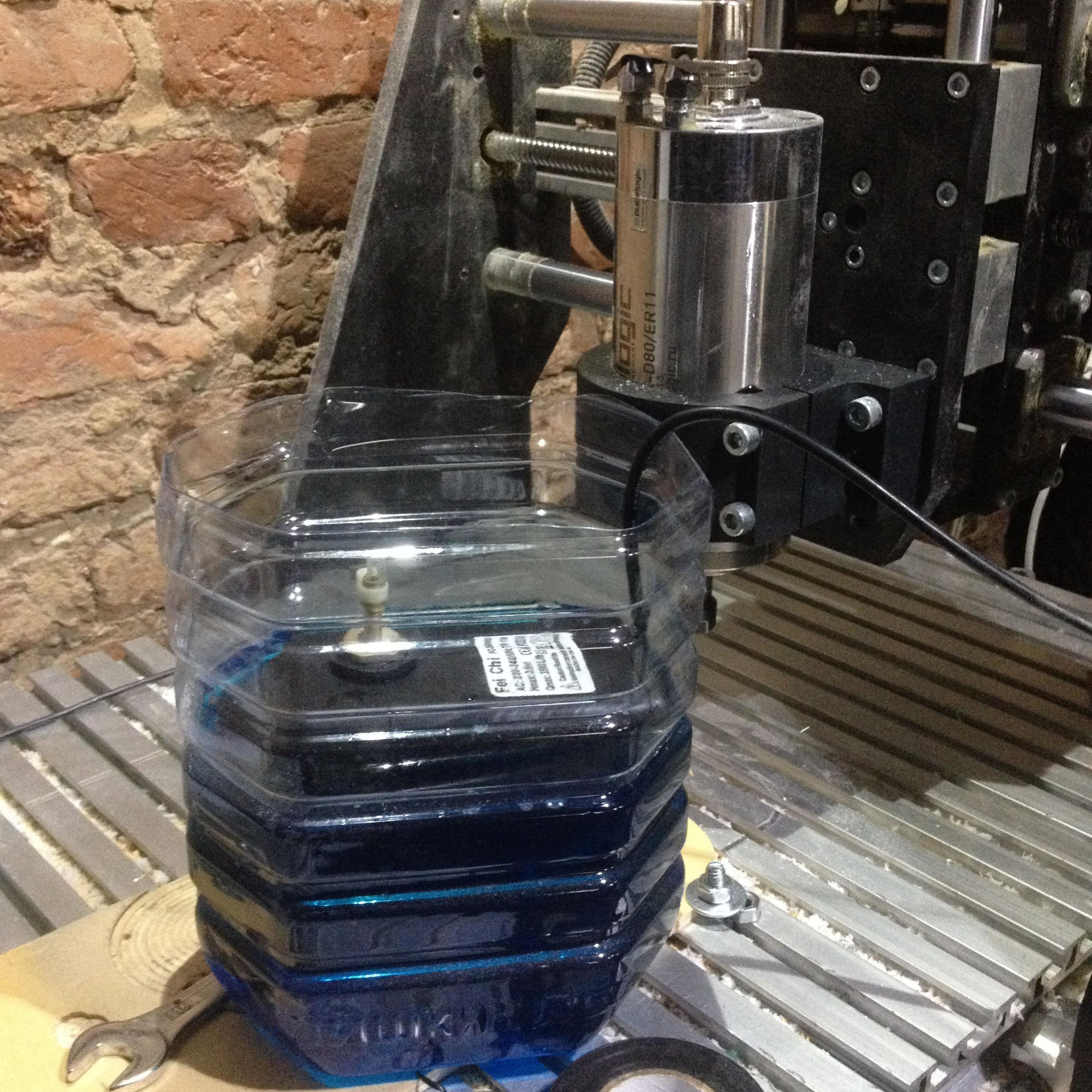
Such a canister warmed up to 60C, if the machine worked 5-6 hours in winter, and up to 70C in summer. The temperature of the spindle body, according to the indications of the infrared thermometer, had a temperature in the comparable range: from 60 to 75. This was enough but very close, but in the next couple of weeks a rather large order for processing was seen and we decided to cool down with a margin.
We had some small change in the bins and a couple of beautiful bimetal thermometers from one of the past projects that we wanted to add somewhere. We also have quite expensive electricity and very cheap cold water, so we decided to use the tap change to organize a secondary circuit that would cool the antifreeze.
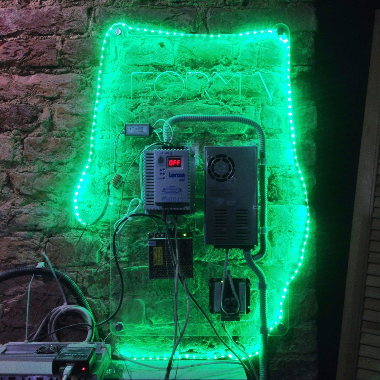
To the right of the machine, we have a shield with an electrician: a frequency converter, power supplies, a dumper, and so on. Everything is mounted on a sheet of plexiglass cut out by a laser, and we did not depart from the given style.
After a couple of hours of modeling, we got this scheme:
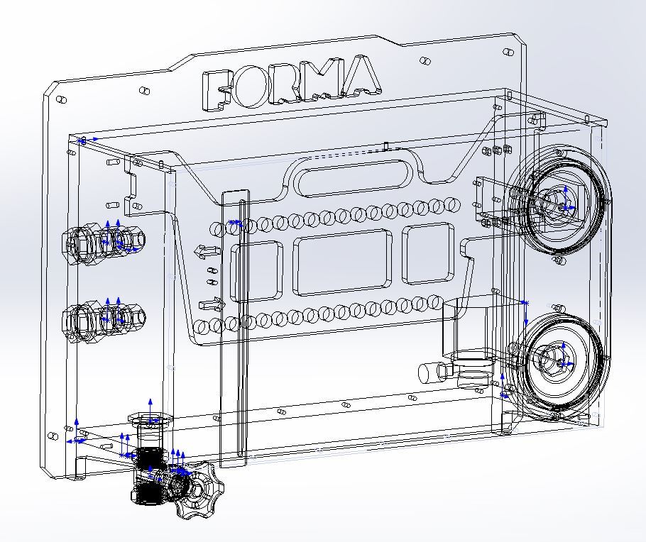
In total, it turned out 12 parts of different thickness: it was decided to make the side parts and the bottom of a 10mm thick sheet so that it was more convenient to drill and cut the thread, and the back wall and front panel - 6mm. We prepared the contours for cutting in DXF, made a specification and sent it to our friends for laser cutting. The next day, we received the parts and spent about half a day on drilling the edges, threading and chamfering.
Then conducted a trial build:
Everything was fine, and the next day we went to pick up a submersible pump from the point of issue of Internet orders. The pump was selected for fountains ZBR ZNFCH-20-1.6. Quite compact and with characteristics just under our task.
It's time for the final assembly. All joints are taped, the screws are tightened and left to dry. Video build can be found here:
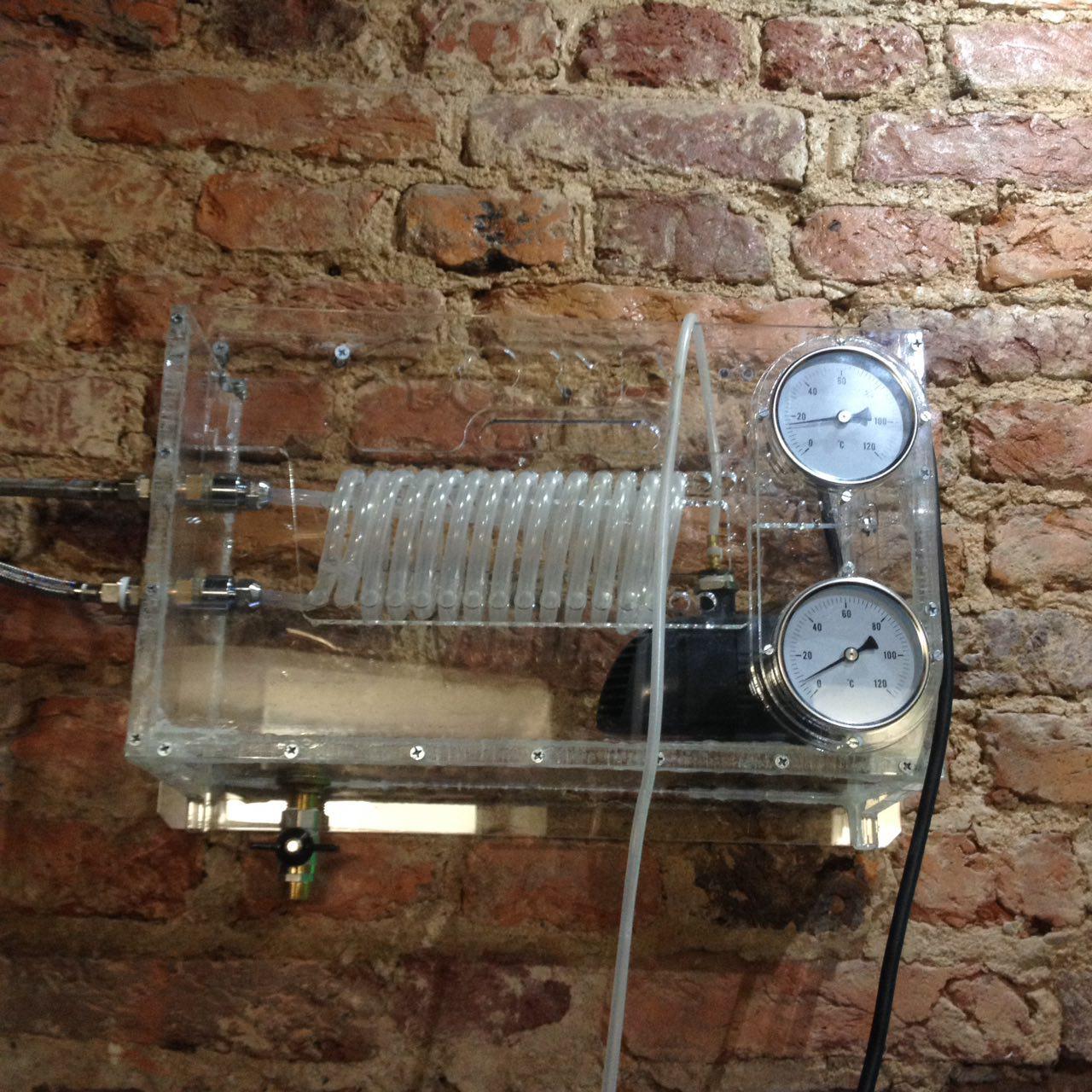
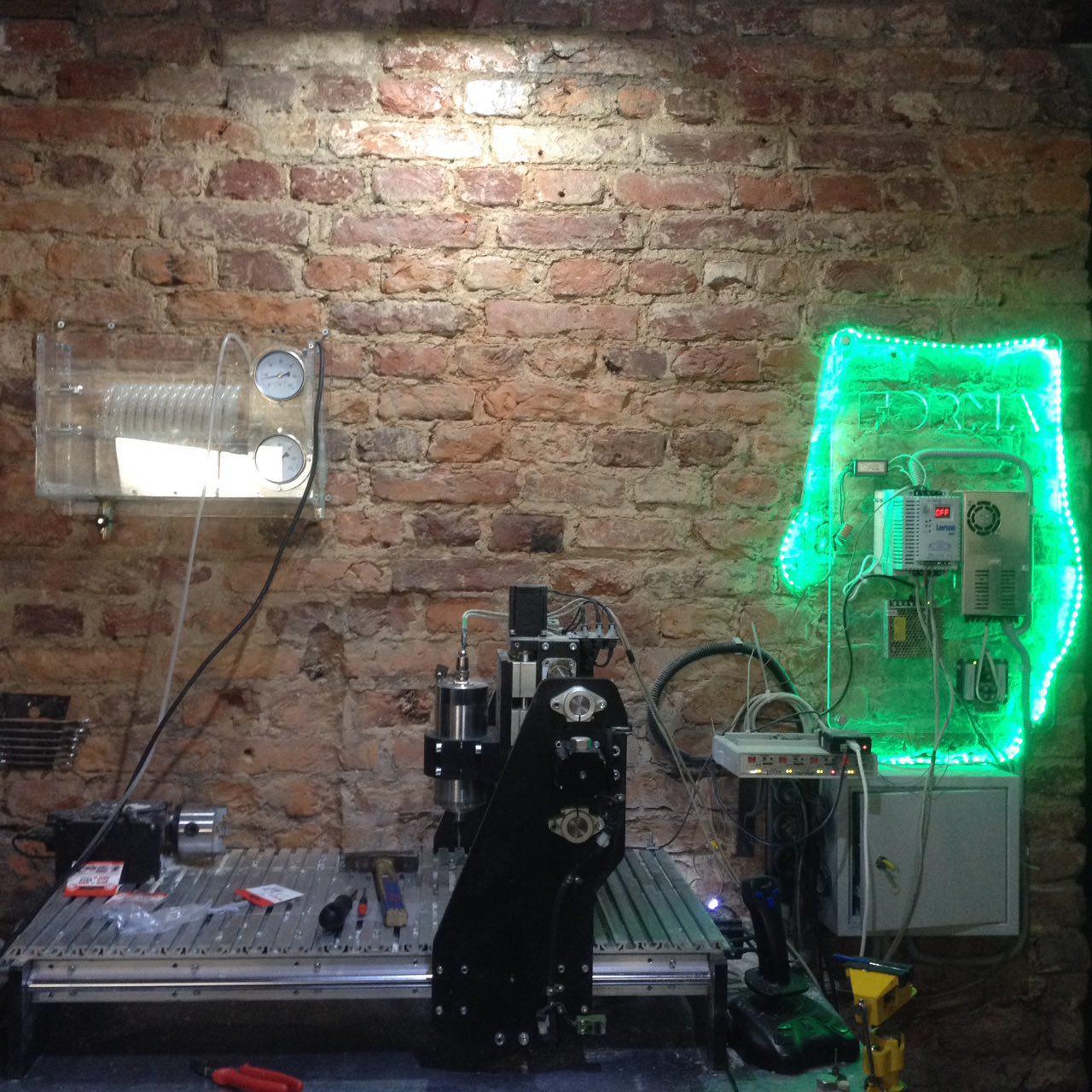
Everything dried out and we successfully installed the unit. Now it looks like this:
Total required:
Total cost: about 6 thousand rubles.
We collected all the documentation, including the model and laser scanning in DXF for laser cutting, into the archive and posted here:
Document in the FORMA group on VK
Archive to Depositfiles
And we opened a channel in Telegram for questions on the assembly and proposals for upgrading.
The day came when it became possible to put in order the cooling of the spindle: the Chinese pump failed. And we thought it was time to stop hiding the canister with antifreeze and the pump under the machine and to do something that would not be ashamed to put in a prominent place. We are an industrial design bureau, after all!
That was how the farm looked immediately after the breakdown:
')
Such a canister warmed up to 60C, if the machine worked 5-6 hours in winter, and up to 70C in summer. The temperature of the spindle body, according to the indications of the infrared thermometer, had a temperature in the comparable range: from 60 to 75. This was enough but very close, but in the next couple of weeks a rather large order for processing was seen and we decided to cool down with a margin.
We had some small change in the bins and a couple of beautiful bimetal thermometers from one of the past projects that we wanted to add somewhere. We also have quite expensive electricity and very cheap cold water, so we decided to use the tap change to organize a secondary circuit that would cool the antifreeze.
To the right of the machine, we have a shield with an electrician: a frequency converter, power supplies, a dumper, and so on. Everything is mounted on a sheet of plexiglass cut out by a laser, and we did not depart from the given style.
After a couple of hours of modeling, we got this scheme:
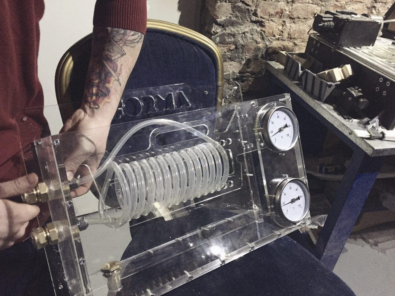
- On the left wall there are two "American" 1/2 "for connecting running water. They have adapters with a collet on a 10mm silicone tube, which spirals through the holes of the cassette (the one with the handle).
- Flowing cold water will flow through the silicon tube and cool the antifreeze through the tube wall. Not super efficient, but in our case, enough.
- The whole structure is suspended from the wall, so a 1/2 ”tap is installed in the bottom of the tank for draining in case you need to remove everything for maintenance or just move it up.
- The bimetallic thermometers on the right also have 1/2 ”threads and are secured with a lock nut through a silicone gasket. A warm refrigerant will flow onto the top thermometer and the thermometer will show its inlet temperature. The thermometer bottom is located next to the inlet of the submersible pump and shows the temperature outgoing stream.
In total, it turned out 12 parts of different thickness: it was decided to make the side parts and the bottom of a 10mm thick sheet so that it was more convenient to drill and cut the thread, and the back wall and front panel - 6mm. We prepared the contours for cutting in DXF, made a specification and sent it to our friends for laser cutting. The next day, we received the parts and spent about half a day on drilling the edges, threading and chamfering.
Then conducted a trial build:
Everything was fine, and the next day we went to pick up a submersible pump from the point of issue of Internet orders. The pump was selected for fountains ZBR ZNFCH-20-1.6. Quite compact and with characteristics just under our task.
It's time for the final assembly. All joints are taped, the screws are tightened and left to dry. Video build can be found here:
Everything dried out and we successfully installed the unit. Now it looks like this:
Total required:
- 12 plexiglass parts
- 2 "American" fittings 1/2 "
- 2 bimetal thermometers
- 1 1/2 "crane
- 5 silicone pads 1/2 "
- placer fasteners M4x0,5
- silicone sealant tube
- 4 meters silicone tube 10mm
- ZUBR ZNFCH-20-1.6 submersible pump
Total cost: about 6 thousand rubles.
We collected all the documentation, including the model and laser scanning in DXF for laser cutting, into the archive and posted here:
Document in the FORMA group on VK
Archive to Depositfiles
And we opened a channel in Telegram for questions on the assembly and proposals for upgrading.
Source: https://habr.com/ru/post/402045/
All Articles