1-Wire bus driver for power controllers less than 5V
The 1-Wire bus driver brought to your attention is not something revolutionary, all the used circuit solutions have long been known. The reason for the publication was the desire not to clutter an article on the software implementation of 1-Wire-master primitives based on PWM and ICP .
The bus driver is used in one of my projects, so the numbering of the elements does not begin with "1."
Signal assignment:
ICP - input for the microcontroller, designed to receive data from the 1-Wire bus;
OCRA - output signal for the microcontroller, designed to modulate the data transmitted on the 1-Wire bus;
PULLUP - output signal for the microcontroller, designed to implement on the 1-Wire bus mode "ACTIVE PULLUP";
3V3 is the supply voltage to which the pins of the ICP, OCRA and PULLUP microcontrollers are tolerant. This voltage does not have to be exactly 3.3V, it can be more or less.
')
The two mandatory criteria are:
- 3V3 voltage must be strictly less than 5V0 voltage (at least by the magnitude of the voltage drop on the parasitic MOSFET Q3 diode in the case of its direct inclusion);
- 3V3 voltage should be greater than the voltage between the gate and the source used MOSFET, guaranteeing their stable opening.
ONEWIRE - 1-Wire bus signal;
5V0 - power for the 1-Wire bus.
Components Q2 and R19 provide modulation of the signal on the 1-Wire bus from the low-voltage part of the driver. R18 is designed to guarantee Q2 closure in the absence of a modulating signal and, to some extent, to protect against ESD (electrostatic discharge) if the driver is executed as a separate module.
The D8 diode assembly is designed exclusively to protect against ESD in the unlikely event that someone wants to connect 1-Wire devices with low-voltage power. For example, the DS18B20 allows a supply voltage range of 3.0V to 5.5V. However, it should be noted that the “ACTIVE PULLUP” mode is possible only from the 1-Wire bus side with + 5V power supply (i.e., low-voltage 1-Wire devices should not be used in the parasite power mode). In addition, to improve the noise immunity parameters of the 1-Wire low-voltage bus, you may need to reduce the R19 rating to a value of 1K inclusive. “Cherry on the cake” - both versions of the 1-Wire bus can be used simultaneously.
On components R19, Q3 and R20 a trivial bidirectional level converter is assembled (for an explanation of the principles of its operation, see the list of references ).
Components R21, Q4, R22 assembled a unidirectional inverting level converter to control Q5, which implements the mode "ACTIVE PULLUP".
Resistors R23 and R24 are designed to limit the flow of current (for example, when a new device is connected to the 1-Wire bus while it is in the "ACTIVE PULLUP" mode).
D9 diode assembly provides protection against ESD from the side of 1-Wire bus.
Bibliography:
Schematic diagram
The bus driver is used in one of my projects, so the numbering of the elements does not begin with "1."
Signal assignment:
ICP - input for the microcontroller, designed to receive data from the 1-Wire bus;
OCRA - output signal for the microcontroller, designed to modulate the data transmitted on the 1-Wire bus;
PULLUP - output signal for the microcontroller, designed to implement on the 1-Wire bus mode "ACTIVE PULLUP";
3V3 is the supply voltage to which the pins of the ICP, OCRA and PULLUP microcontrollers are tolerant. This voltage does not have to be exactly 3.3V, it can be more or less.
')
The two mandatory criteria are:
- 3V3 voltage must be strictly less than 5V0 voltage (at least by the magnitude of the voltage drop on the parasitic MOSFET Q3 diode in the case of its direct inclusion);
- 3V3 voltage should be greater than the voltage between the gate and the source used MOSFET, guaranteeing their stable opening.
ONEWIRE - 1-Wire bus signal;
5V0 - power for the 1-Wire bus.
Components Q2 and R19 provide modulation of the signal on the 1-Wire bus from the low-voltage part of the driver. R18 is designed to guarantee Q2 closure in the absence of a modulating signal and, to some extent, to protect against ESD (electrostatic discharge) if the driver is executed as a separate module.
The D8 diode assembly is designed exclusively to protect against ESD in the unlikely event that someone wants to connect 1-Wire devices with low-voltage power. For example, the DS18B20 allows a supply voltage range of 3.0V to 5.5V. However, it should be noted that the “ACTIVE PULLUP” mode is possible only from the 1-Wire bus side with + 5V power supply (i.e., low-voltage 1-Wire devices should not be used in the parasite power mode). In addition, to improve the noise immunity parameters of the 1-Wire low-voltage bus, you may need to reduce the R19 rating to a value of 1K inclusive. “Cherry on the cake” - both versions of the 1-Wire bus can be used simultaneously.
On components R19, Q3 and R20 a trivial bidirectional level converter is assembled (for an explanation of the principles of its operation, see the list of references ).
Components R21, Q4, R22 assembled a unidirectional inverting level converter to control Q5, which implements the mode "ACTIVE PULLUP".
Resistors R23 and R24 are designed to limit the flow of current (for example, when a new device is connected to the 1-Wire bus while it is in the "ACTIVE PULLUP" mode).
D9 diode assembly provides protection against ESD from the side of 1-Wire bus.
Appearance of the device (on the breadboard)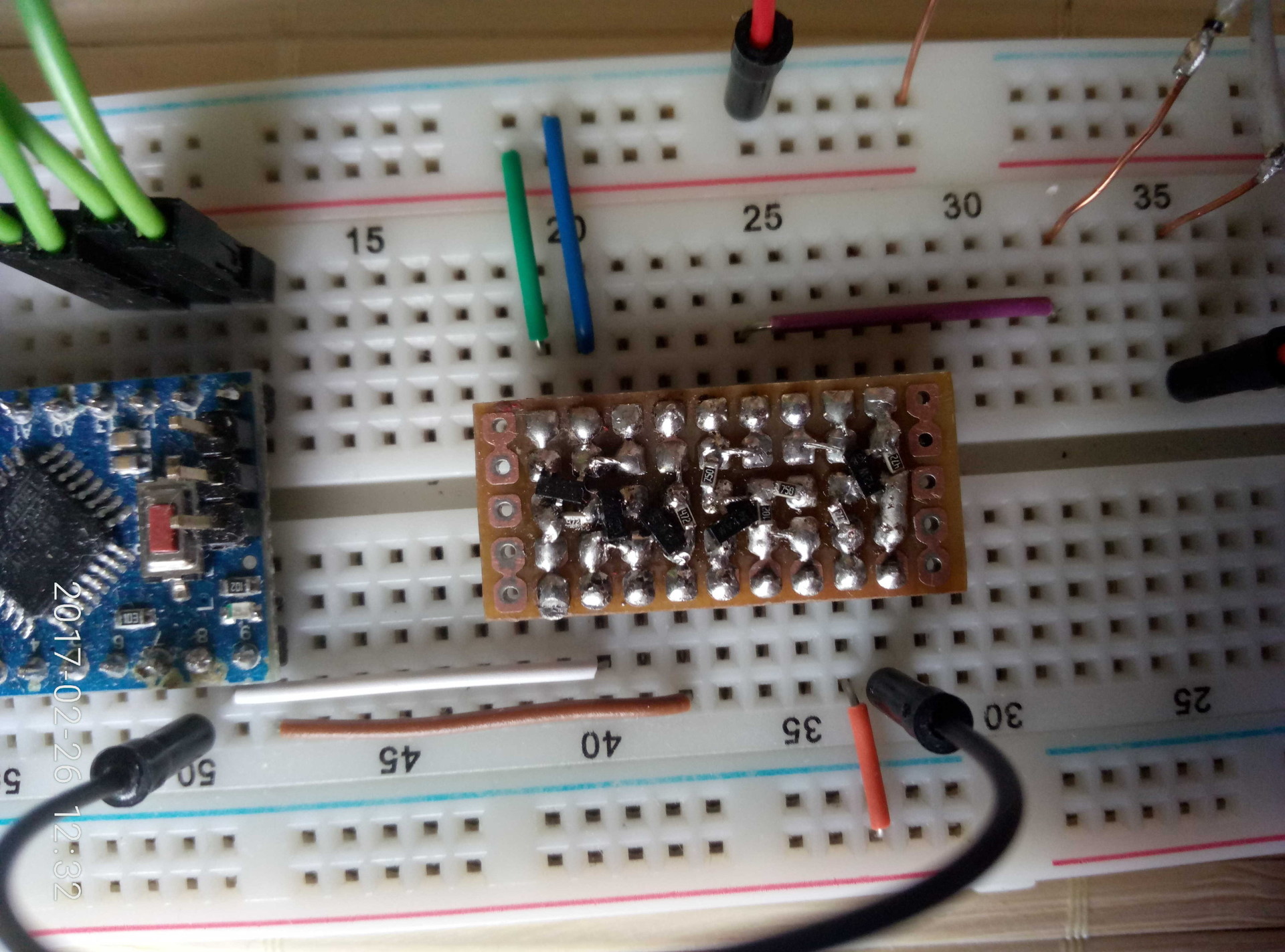
Bibliography:
Source: https://habr.com/ru/post/401913/
All Articles