Robot promoter - Oscar. Manipulator
Today we want to talk about the device manipulator promotional robot Oscar. Although initially no tough industrial requirements were imposed on the manipulator, nevertheless, our goal was to make a practical and aesthetic decision that was not very expensive and relatively easy to make at home.
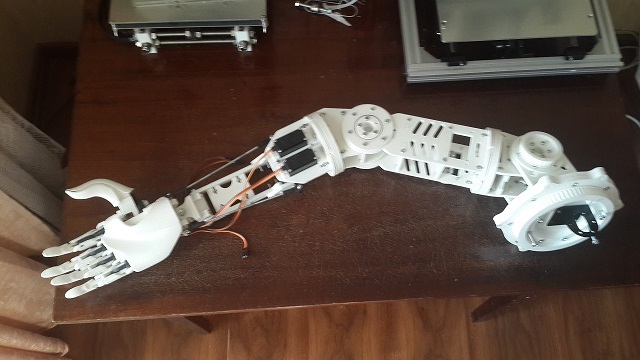
The length of the manipulator from shoulder to fingertips is 0.6 meters, weight - 2.25 kg. Production materials - PLA. The manipulator can be divided into 3 components:
')
- Bionic brush
- Wrist (2 degrees of freedom)
- Elbow and shoulder joints (5 degrees of freedom)
This is due to the fact that each of the components has its own technical solution.
Bionic brush
For a quick and easy start, it was decided to base the open project Hackberry. The design of the brush slightly modified to fit your needs.
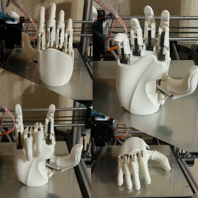
Fingertip controls are located in the brush itself. There are three of them. One - on the thumb, one - on the index finger, and another one - on all others.
With this ingenious grip, a robot can take some kind of volumetric object, such as a bottle of mineral water, and also shake hands with a person or grab a smaller / thin object, holding it between the thumb and forefinger.
Wrist
The wrist has a differential drive and is controlled by a pair of braces. One end of the rod is attached to the base of the brush, the other to the servo arm. Thus, it turns out 2 degrees of freedom.
For greater aesthetics, master models for the forearm body were designed and printed on a 3D printer.
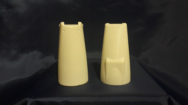
And the case was made by vacuum molding. This is the anthropomorphic hand.
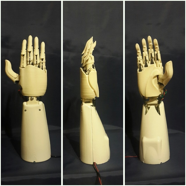
I think it looks pretty.
Elbow and shoulder joints
Here, in my opinion, the most interesting begins. In order to achieve an acceptable behavior of these joints, in contrast to the very smooth development of the wrist with a wrist, we had to pretty much tinker with both mechanics and control.
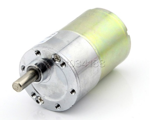
It was decided to implement the control by servos based on conventional 37Dx70L DPT, which we had in the right quantity from previous projects.
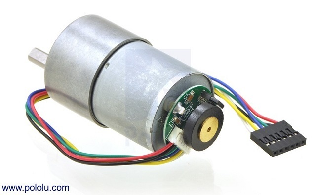
In general, we liked the DPT data, but they have one drawback, namely the noise level. In the future we plan to replace them with identical ones, but less noisy.
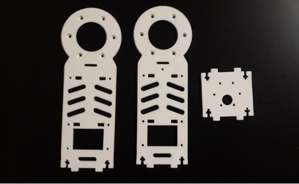
Bearings and profiles printed on a 3D printer form the basis of the bearing structure of the joints. The bearing consists of four half-grooves, strung together in pairs, and metal balls of 4, 6 and 8 millimeters.
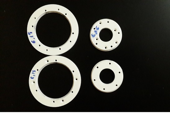
Profiles have grooves for connection among themselves, also additional stiffening ribs are used. All this happiness bolted.
Initially, in some degrees, the motor shaft was attached to the bearing through a coupling.
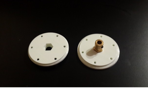
But in the absence of drives with the right speeds and effort, we redid the design for belt gears.
Serva
The following requirements were imposed on the management of “Cerva”:
- Output Shaft Position Control
- Speed adjustment
- Force adjustment (asterisk condition)
First, we looked for similar projects on the Internet - we are not the only ones who are so smart. Taking as a basis one of the projects we liked, we were very unhappy with the result. The positioning of the drive shaft has proven to be very mediocre.
As a result, we were only satisfied with the development of our custom solution. In this question, the article “Maintaining the position in the servo drive: subordinate regulation vs stepping mode” helped a lot, for which the author thanks a lot!
The general control scheme is as follows (the scheme is taken from the above article):
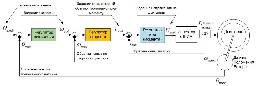
As a position sensor, our circuit uses the magnetic encoder as5045, and the current readings are taken using the GY-712 5A sensor.
Initially, the Arduino Mega was used to control the drives, and although the result was satisfactory, we ended up switching to a more reliable STM32F4 tube.
Here is the result of the drive:
Having achieved an acceptable result in controlling the “serva” output shaft without load, he was placed in the arm of the manipulator. And “suddenly” it turned out that controlling the drive and the manipulator are two different things. The problem was that the “sausage” manipulator in the target points, the so-called “servo bounce” was present. We tried various regulatory factors, but it was all in vain.
The cause of our troubles was the notorious gravity. In the hanging position (when the arm is lowered vertically down), for the deviation of 10 degrees in the shoulder joint, some coefficients of the regulators are necessary, and for achieving the same deviation in the horizontal position, other coefficients. Since Since the system is not too dynamic, we used the usual three-axis accelerometer to determine the level of the influence of gravity and subsequently compensate it, which solved our problem. This decision does not claim to be a panacea - it's just our way. Perhaps among the readers of our article there are experienced electric drivers who can advise something.
Here is a video test of one of the degrees of the shoulder (as it turned out, the most difficult degree in terms of management).
And of course, the entire video of the manipulator:
At last
In general, we are satisfied with the implementation of the first version of the manipulator. The average error of all the “serv” varies in the range of 0.2 - 1 degree (we should not do this surgery with this manipulator). I didn’t really like the grip - too heavy (350 grams). Most likely we will develop our own. In the future, we want to improve the accuracy of all degrees, to alter the mechanics of the wrist - to put there also our "custom" server and make a security system.
What's next?
Now we complete the work on the head Oscar-a, which will be discussed in the next article.
Thanks for attention! Have a nice day, everyone!

Source: https://habr.com/ru/post/401887/
All Articles