Evolution on the roof
Friends, today we will tell you how, over our heads, absolutely silently, the technician made a small step forward, or how one Petersburg basement suddenly developed a line of chillers.
So, in any new or well renovated old building, there is a central air conditioning system. It maintains the microclimate and, together with the ventilation system, provides an atmosphere suitable for working people and machines.
The key element of such a system is the chiller.
')
Wiki chiller
Chiller works as follows:
1. In the freon circuit (green) gaseous freon enters the compressor, which compresses it several times.
2. Compressed, but still gaseous freon passes through a condenser, where a lower temperature is added to the high pressure, as a result of which the freon condenses into the liquid phase (therefore, the condenser is called a condenser).
3. Liquid freon passes through a thermal expansion valve, which, according to the sensor signals, regulates its flow.
4. Liquid freon enters the evaporator, where it receives heat from the circulating water (it comes from the cold consumer, for example, an office air conditioner or the cooling system of the machine). Having received a sufficient amount of heat from the water, freon evaporates, and everything repeats itself again: the water from the consumer has cooled, and the freon flew further.
Scheme
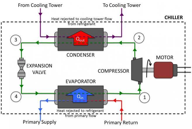
This scheme of the refrigeration unit is as old as the whole industry and mankind has never invented anything more refined. All currently known thermal cycles fit into the Carnot cycle. So, like the automotive industry, the “refrigerator” is working on parts: condensers, evaporators, compressors, etc. are being improved. Moreover, this small number of parts gave a fairly large number of circuits and types of refrigeration machines, each of which found its own field of application.
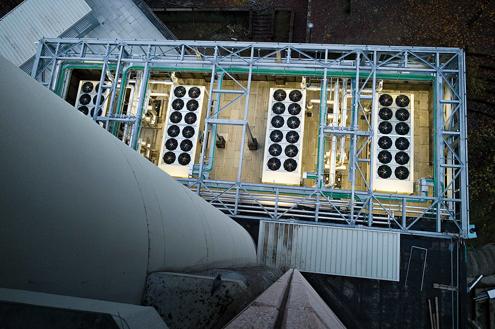
In this article we are talking about those large machines that are installed on the roofs of office buildings, factories, data centers, etc. Such machines have a capacity from 0.5 MW to 2-3 MW. Then it makes sense to build high-grade cooling towers.
In a classic way, these cars look like this:
On the lower tier, we see two screw compressors (green). Behind the compressors you can see the shell-and-tube evaporator (the photo below is painted black). On the second tier there are V-shaped cooling towers, which play the role of a condenser. Well, of course, electrical cabinet with power electronics and control unit.
And now the preface.
A year ago, Felzer, which at that time successfully produced chillers of various capacities, modifications and appointments, contacted our bureau. The situation was such that the company had a lot of diversified orders, for each of which it was necessary to choose a car from the existing lines and slightly “finish” the contours, metal, and so on. Components were ordered for each machine separately, the metal was produced according to standard documentation, but with adjustments.
The company management decided to develop a line of chillers that would cover the largest range of orders, while reducing the number of parts unique to each machine to zero, and, of course, to make it look good. I wanted to have a number of standard components right in stock, choose what you need and assemble the ordered model.
The design department of the company has been loaded with routine. If you hire new designers, you must first train them with all the technical nuances, then control the design process, after which you either need to be checked or fired. It was decided to outsource this task to us. It so happened that the chief designer and general director learned from Professor Barilovich (Prof. Barilovich ) at the Polytech, therefore the subject matter of the refrigerator and heat engineering as a whole was more than familiar.
Our bureau, starting a deep study of the topic, found out that, firstly, yes, there are screw compressors everywhere, and, secondly, they are often reserved at responsible facilities, that is, they are doubles.
Screw compressor looks like this:

And it works like this:

Everything is clear: the rotors rotate, capture the volume of gas, push it along the axis, while the working chamber is geometrically reduced, compressing the gas. The power of such compressors is governed by the geometry of the rotors and the power of the electric motors that drive them. A wide range of one model is not covered. You need to install one or two plus a reserve, so that a special modularity cannot be built.
What is the alternative?
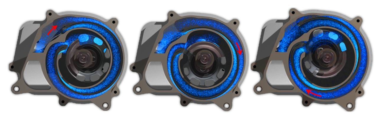
Spiral compressors. They work on a similar principle, but instead of screws they use concentric spirals.
Scheme of work:
On such compressors, low-end machines (of lesser capacity) compressors are built in assemblies of two (duo), three (trio) and four (quatro) units. This is due to the fact that the most powerful compressors are limited by the height of the spirals themselves. If the power of the electric motor that drives one of the spirals can be increased, there are some problems with the spiral itself. Spirals of greater height are quite difficult to produce, and this is due to a whole host of problems with strength, machining, control, etc.
For a 250kW machine, you can apply an assembly of such compressors, but for a 1MW machine, you would have to force the entire lower tier with compressor assemblies, so there would be no room even for an evaporator, you would have to grow the machine up, but not. There is modularity, but it is not enough for the entire range of the ruler.
But exactly at the time when we started to develop, an interesting thing happened: Copeland (manufacturer of scroll compressors, a division of Emerson) announces the news that they managed to produce more high-power spirals, and if the 30-horsepower unit used to be the senior compressor forces, now - 60 horsepower ( Copeland page about compressors 60hp ).
And here we understood: here it is! Began active coordination with the designers of the customer, preliminary calculations and estimations of the layout.

One of the key arguments in favor of this decision was the issue of reservations. If the machine on screw compressors needed to be backed up, then the same compressor was additionally installed, and this, by the way, is one of the most expensive components of the chiller. In our case, it was possible to put a smaller number of compressors in reserve, since the probability of failure of one of the two screw compressors is higher than the probability of failure of six of the twelve compressors at the same time.
Together with the customer’s management, we made the decision to do just that, and the AirPlus line was gradually born. Here, a good help was the fact that Felzer received an order for a chiller of that capacity that fell into the range of our line, so there was a great opportunity to “roll back” our design documentation in real production conditions.
Here we will make a remark that the connection with the production was only via Skype, the plant itself is located in Riga on the basis of the Riga Carriage-Rigging Plant (RVR). We had a list of production equipment, a set of technical director’s hoteles, a customer’s designer’s vision, and a lot of stories about how to do it .
The routine began for us too: the chiller was built, we received feedback, made adjustments to the design documentation.
The idea of our line was not new. We grew the chiller from the junior car to the older car by lengthening the car. Here it was necessary to catch a balance between the length of a standard sheet, the working area of a sheet bending machine, the dimensions of the transport containers, the strength of the whole structure and other factors.
A trial machine was built and shipped, after which an order came for two of the almost most powerful machines of the line. It is the ones we were worried about, that they will bend when traversing, that the frame “will go with a screw” and so on. Of course, we made the necessary calculations, but even the most accurate simulation using the finite element method does not always produce a result that describes the real state of affairs.
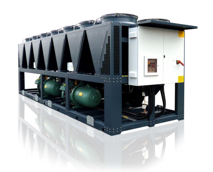
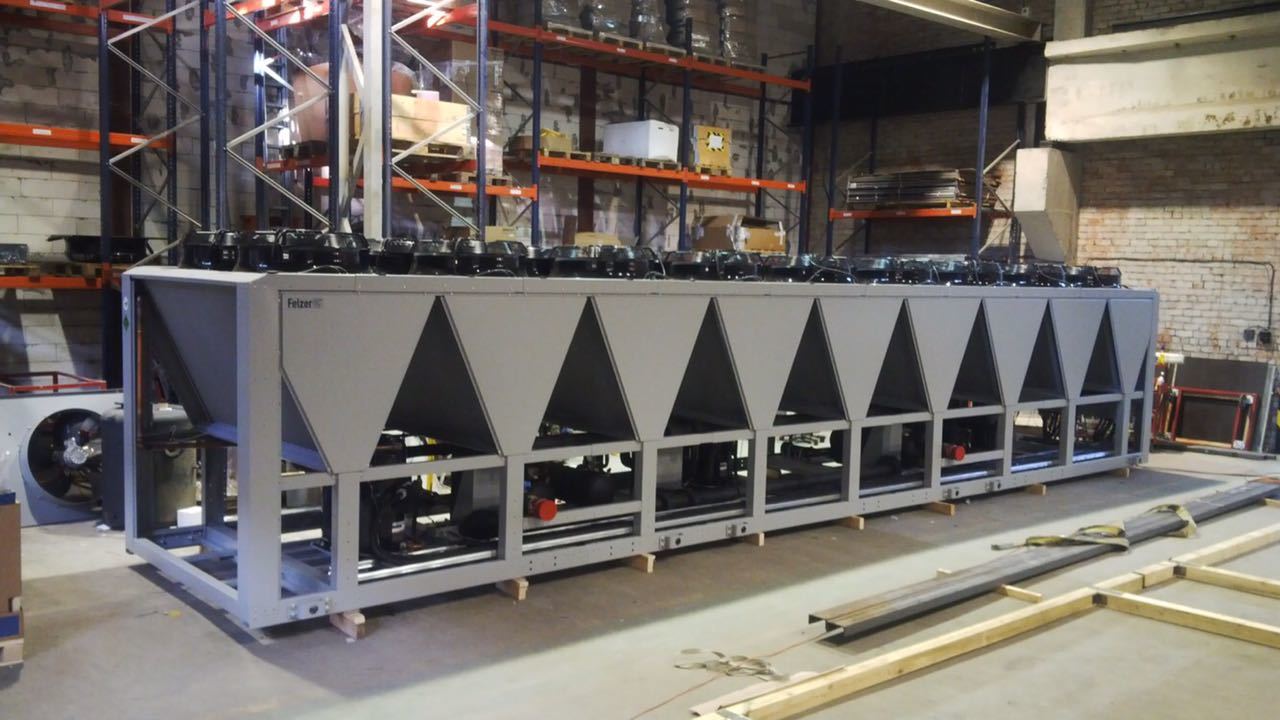
These cars are:
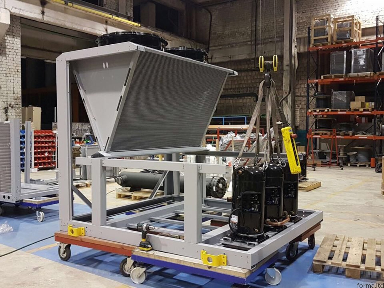
Mounted first tier: visible compressor assembly, two plate evaporator
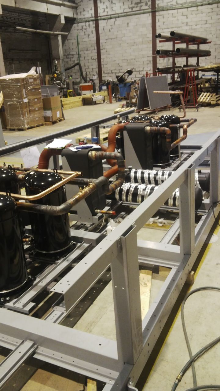
Unsoling pipes cooling towers:

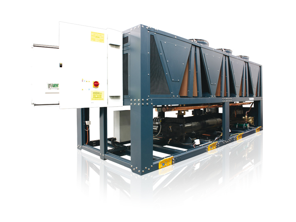
Mounted components of the electrical cabinet:
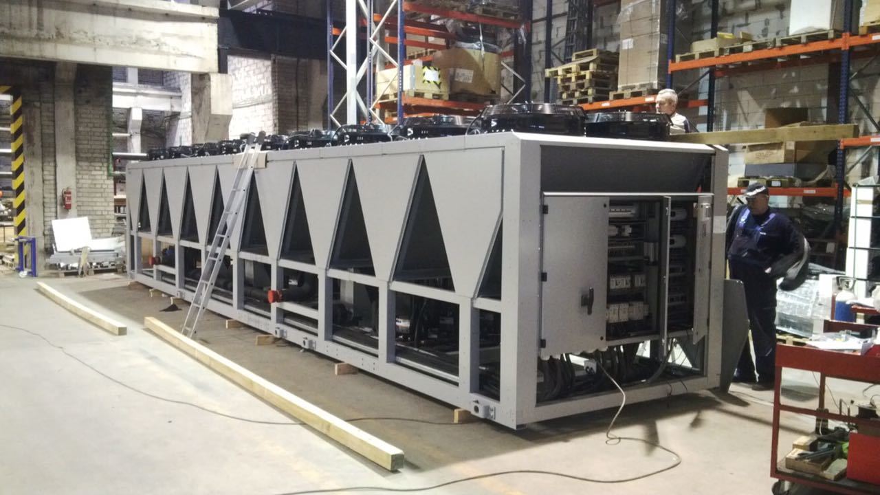
Machine assembly:
Epilogue.
To our dismay, we found that we were not pioneers in this area. Many companies that have a large R & D unit have already had their finger on the pulse and have launched similar lines or expanded old ones almost in parallel with us. But, be that as it may, it was quite pleasant to be on the front line.
→ Page with photos on the website of the Bureau FORMA
→ Page with other works in the field of industry
So, in any new or well renovated old building, there is a central air conditioning system. It maintains the microclimate and, together with the ventilation system, provides an atmosphere suitable for working people and machines.
The key element of such a system is the chiller.
')
Chiller (Water-cooling machine) is an apparatus for cooling a liquid using a vapor compression or absorption refrigeration cycle. After cooling in the chiller, the liquid can be supplied to the heat exchangers to cool the air (fan coil units) or to remove heat from the equipment. During the cooling of the liquid, the chiller creates excess heat that must be removed to the environment.
Wiki chiller
Chiller works as follows:
1. In the freon circuit (green) gaseous freon enters the compressor, which compresses it several times.
2. Compressed, but still gaseous freon passes through a condenser, where a lower temperature is added to the high pressure, as a result of which the freon condenses into the liquid phase (therefore, the condenser is called a condenser).
3. Liquid freon passes through a thermal expansion valve, which, according to the sensor signals, regulates its flow.
4. Liquid freon enters the evaporator, where it receives heat from the circulating water (it comes from the cold consumer, for example, an office air conditioner or the cooling system of the machine). Having received a sufficient amount of heat from the water, freon evaporates, and everything repeats itself again: the water from the consumer has cooled, and the freon flew further.
Scheme
This scheme of the refrigeration unit is as old as the whole industry and mankind has never invented anything more refined. All currently known thermal cycles fit into the Carnot cycle. So, like the automotive industry, the “refrigerator” is working on parts: condensers, evaporators, compressors, etc. are being improved. Moreover, this small number of parts gave a fairly large number of circuits and types of refrigeration machines, each of which found its own field of application.
In this article we are talking about those large machines that are installed on the roofs of office buildings, factories, data centers, etc. Such machines have a capacity from 0.5 MW to 2-3 MW. Then it makes sense to build high-grade cooling towers.
In a classic way, these cars look like this:
On the lower tier, we see two screw compressors (green). Behind the compressors you can see the shell-and-tube evaporator (the photo below is painted black). On the second tier there are V-shaped cooling towers, which play the role of a condenser. Well, of course, electrical cabinet with power electronics and control unit.
And now the preface.
A year ago, Felzer, which at that time successfully produced chillers of various capacities, modifications and appointments, contacted our bureau. The situation was such that the company had a lot of diversified orders, for each of which it was necessary to choose a car from the existing lines and slightly “finish” the contours, metal, and so on. Components were ordered for each machine separately, the metal was produced according to standard documentation, but with adjustments.
The company management decided to develop a line of chillers that would cover the largest range of orders, while reducing the number of parts unique to each machine to zero, and, of course, to make it look good. I wanted to have a number of standard components right in stock, choose what you need and assemble the ordered model.
The design department of the company has been loaded with routine. If you hire new designers, you must first train them with all the technical nuances, then control the design process, after which you either need to be checked or fired. It was decided to outsource this task to us. It so happened that the chief designer and general director learned from Professor Barilovich (Prof. Barilovich ) at the Polytech, therefore the subject matter of the refrigerator and heat engineering as a whole was more than familiar.
Our bureau, starting a deep study of the topic, found out that, firstly, yes, there are screw compressors everywhere, and, secondly, they are often reserved at responsible facilities, that is, they are doubles.
Screw compressor looks like this:
And it works like this:
Everything is clear: the rotors rotate, capture the volume of gas, push it along the axis, while the working chamber is geometrically reduced, compressing the gas. The power of such compressors is governed by the geometry of the rotors and the power of the electric motors that drive them. A wide range of one model is not covered. You need to install one or two plus a reserve, so that a special modularity cannot be built.
What is the alternative?
Spiral compressors. They work on a similar principle, but instead of screws they use concentric spirals.
One helix remains stationary, and the other - performs eccentric movements without rotation, thereby ensuring the transfer of the working medium from the suction cavity to the discharge cavity.Wiki - scroll compressor .
Scheme of work:
On such compressors, low-end machines (of lesser capacity) compressors are built in assemblies of two (duo), three (trio) and four (quatro) units. This is due to the fact that the most powerful compressors are limited by the height of the spirals themselves. If the power of the electric motor that drives one of the spirals can be increased, there are some problems with the spiral itself. Spirals of greater height are quite difficult to produce, and this is due to a whole host of problems with strength, machining, control, etc.
For a 250kW machine, you can apply an assembly of such compressors, but for a 1MW machine, you would have to force the entire lower tier with compressor assemblies, so there would be no room even for an evaporator, you would have to grow the machine up, but not. There is modularity, but it is not enough for the entire range of the ruler.
But exactly at the time when we started to develop, an interesting thing happened: Copeland (manufacturer of scroll compressors, a division of Emerson) announces the news that they managed to produce more high-power spirals, and if the 30-horsepower unit used to be the senior compressor forces, now - 60 horsepower ( Copeland page about compressors 60hp ).
And here we understood: here it is! Began active coordination with the designers of the customer, preliminary calculations and estimations of the layout.
One of the key arguments in favor of this decision was the issue of reservations. If the machine on screw compressors needed to be backed up, then the same compressor was additionally installed, and this, by the way, is one of the most expensive components of the chiller. In our case, it was possible to put a smaller number of compressors in reserve, since the probability of failure of one of the two screw compressors is higher than the probability of failure of six of the twelve compressors at the same time.
Together with the customer’s management, we made the decision to do just that, and the AirPlus line was gradually born. Here, a good help was the fact that Felzer received an order for a chiller of that capacity that fell into the range of our line, so there was a great opportunity to “roll back” our design documentation in real production conditions.
Here we will make a remark that the connection with the production was only via Skype, the plant itself is located in Riga on the basis of the Riga Carriage-Rigging Plant (RVR). We had a list of production equipment, a set of technical director’s hoteles, a customer’s designer’s vision, and a lot of stories about how to do it .
The routine began for us too: the chiller was built, we received feedback, made adjustments to the design documentation.
The idea of our line was not new. We grew the chiller from the junior car to the older car by lengthening the car. Here it was necessary to catch a balance between the length of a standard sheet, the working area of a sheet bending machine, the dimensions of the transport containers, the strength of the whole structure and other factors.
A trial machine was built and shipped, after which an order came for two of the almost most powerful machines of the line. It is the ones we were worried about, that they will bend when traversing, that the frame “will go with a screw” and so on. Of course, we made the necessary calculations, but even the most accurate simulation using the finite element method does not always produce a result that describes the real state of affairs.
These cars are:
Mounted first tier: visible compressor assembly, two plate evaporator
Unsoling pipes cooling towers:
Mounted components of the electrical cabinet:
Machine assembly:
Epilogue.
To our dismay, we found that we were not pioneers in this area. Many companies that have a large R & D unit have already had their finger on the pulse and have launched similar lines or expanded old ones almost in parallel with us. But, be that as it may, it was quite pleasant to be on the front line.
→ Page with photos on the website of the Bureau FORMA
→ Page with other works in the field of industry
Source: https://habr.com/ru/post/401881/
All Articles