The open project of the electric motor control module. Start
The main purpose of the module is to control synchronous brushless motors (BLDC, BLAC, PMSM ...) with a trapezoidal or sinusoidal voltage, with speed-position sensors or without sensors . In addition, the module has small dimensions, a fairly wide range of supply voltages, various debugging channels, wired and wireless communications.
The power of the motors controlled by the module can be within a few hundred watts and voltage up to 30V. These are engines of various mechanisms and devices, such as: 3D printers, automatic doors, automatic shutters, autonomous pumps, fans, locks, power tools, position stabilizers, motors and RC servomechanisms of models, robots, and so on.
But the use of the module is not limited to this. It can be used with minor additions to control solenoids, stepper motors, to control lighting, as a powerful charger, as a voltage regulator, as a powerful source of audio signals, as a high-amp key with a current meter, and simply as a debugging platform.
In short, such a module in the farm engineer can be very useful.
')
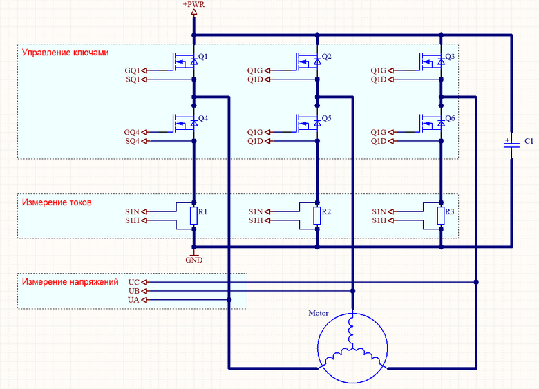
All these properties of the module are obtained thanks to the classical 3-phase half-bridge circuit with current and voltage sensors and a productive microcontroller.
(Click to enlarge)
To speed up the process of developing a power circuit, one of the typical projects offered by TI was taken as a basis.
I settled on the project board TIDA-00901 .

The board has good characteristics: current up to 20 A, engine power up to 200 W, rated voltage 12 V. Designed for use in a car.
The DRV8305 microcircuit is used as a power key driver . Some searches led to the conclusion that this is one of the best driver ICs for such applications.
A very useful development is the document Automotive 12 V 200 W (20 A) BLDC Motor Drive Reference Design .
The board has a specific round shape, the C2000 LaunchPad controller is used as a control element. Unfortunately, the software is provided not fully open in the part of the motor control libraries. C2000 LaunchPad is made on the basis of DSP processor family F2802x Piccolo. This family of processors is specialized for the development of simple energy converters, and is not distinguished by great versatility and volume of resources.
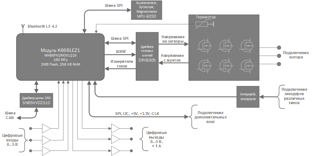
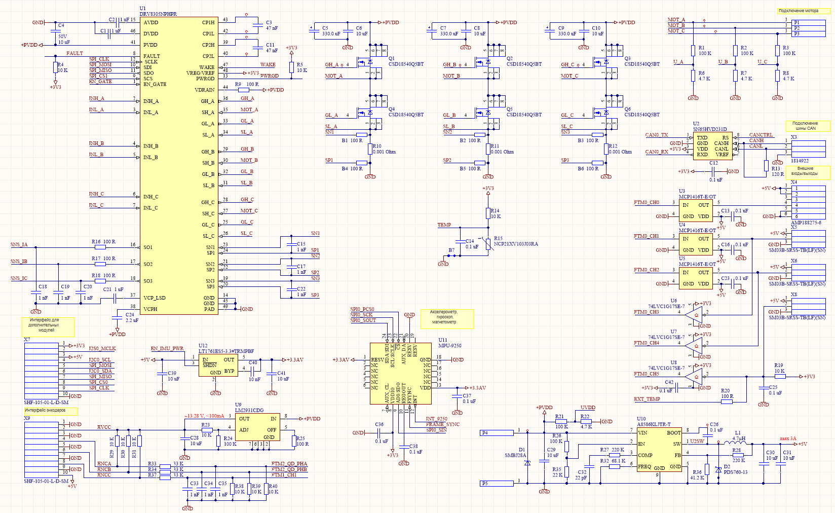
Module architecture
In this project, it was decided to execute the module in the form of a composite structure of 2 boards. The main board contains the power driver, power subsystem and some peripheral functions. A processor board is installed on the main board. As the processor is selected
K66BLEZ1 project board (more articles on this project - 1 , 2 , 3 , 4 ) with a Kinetis microcontroller from NXP family based on the ARM Cortex-M4 core . ( 180 MHz, 2 MB of flash memory, 256 KB of RAM + micro SD card, real-time clock with autonomous power, USB device / host high speed, separate Bluetooth LE 4 / ZigBee chip )
(Click to enlarge)
The module is powered in the voltage range from 8.5 to 30 V. Several temperature sensors - in the microcontroller, near the power switches and one external protect the module and the motor from dangerous overheating. The entire element base is selected for operation at temperatures up to -40 degrees. C.
Power motor control keys are designed for pulse current up to 200 A. Current measurement is made by resistive shunts with a resistance of 0.001 Ohm. Thanks to the adjustable amplifiers built into the DRV8305 driver chip, the module can measure currents from 300 A to 0.1 A.
The CAN bus allows you to combine many of these modules into a common synchronized network.
The MPU-9250 microcircuit is useful in the case when the orientation of the module in space and inertial navigation is required, as well as for monitoring vibrations and impacts.
The built-in DC-DC converter with an output voltage of 5V is designed for currents up to 3.5 A. The module itself consumes no more than 150 mA from this converter, the rest of the current can be transferred to the external load from connector X4. Connector X4 is convenient to use for connecting lighting and display elements, such as LED RGB tapes based on WS2812B chips and the like. The processor hardware supports the generation of bit-coding protocol in digital outputs of the WS2812B format, as well as PPM, PCM, PWM coding. Likewise, the module can accept PPM and PCM signals without any difficulty with minimal CPU usage.
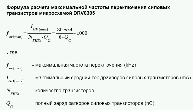
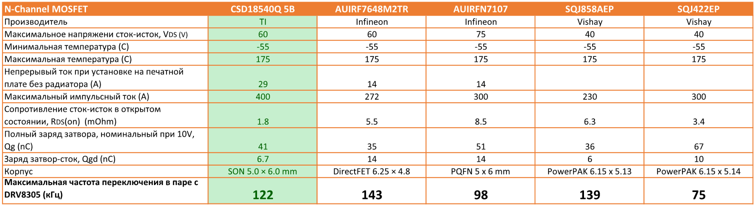
Calculation of the maximum switching frequency and justification of the choice of power transistors
Recheck the comparison table of transistors proposed in the document from TI . All parameters are rewritten from datasheets.
(Click to enlarge)
Here I, like the TI specialists, chose the CSD1854Q5B. The maximum current is the best choice. And the switching frequency of 122 kHz goes far beyond the reasonable limit achievable with control from the Kinetis family.
Calculation of the maximum current ripple and justification of the choice of filter capacitors
Current pulsations directly affect the heating and lifetime of capacitors, especially electrolytic ones. Therefore, it is necessary to select capacitors by type and nominal, taking into account the estimated service life and maximum currents.
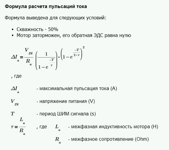
Using this formula, you should check whether the module is able to control this motor without exceeding the maximum capacitor currents.
As TI specialists calculated, with a capacitor indicated in the diagram, a module at a PWM frequency of 40 KHz can power a locked motor with a current through the windings of more than 80 A for a long time.
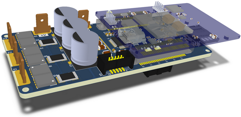
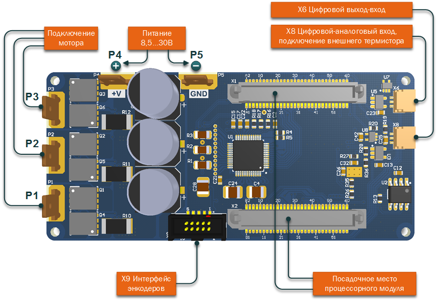
The circuit board of the module
(Click to enlarge)

(Click to enlarge)
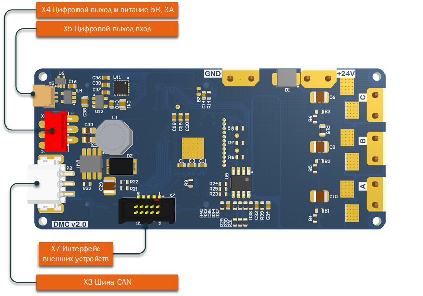
Connector locations
View of the main board from above:
(Click to enlarge)
View of the main board below
(Click to enlarge)
Dimensions
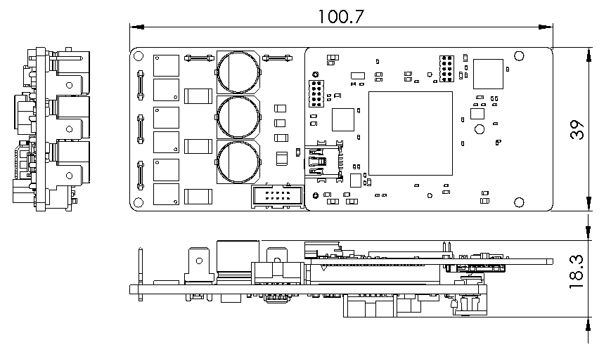
(Click to enlarge)
Project repository
All materials related to the project are stored here .
The circuit and the printed circuit board are developed in the Altium Designer 17.0.6 environment.
In the repository you can find the 3D model of the assembly in the STEP format.
There is also a calculation file for the DC-DC converter on the A8586 in the Mathcad format.
The software part of the project will be discussed in the next article.
Source: https://habr.com/ru/post/401873/
All Articles