How a butterfly shoves, or the complexity of a simple extruder

Good day to you, dear geeks and sympathizers! According to the results of the voting in my previous publication, I want to begin a series of publications about building a simple and inexpensive, but fast and reliable 3D printer.
Why not just buy? The reason is simple: none of the affordable printers (up to 300 euros) do not have the required amount of parameters out of the box, and the idea of buying a device with the need for significant rework did not inspire me too much.
Since the description of the construction of the entire printer will require too many letters and other characters, I will describe its functional blocks separately. With this approach, it is possible to describe the features of individual components of a structure much more deeply.
')
The most important part of the printer, namely the hot end, I described in my previous publication. It is time to go to the most controversial site: the extruder drive.
So, let's begin. Some lyrics: I dreamed of a fast printer. Observations on the ordeals of fellow enthusiasts convinced me that dragging the extruder drive mechanism along with the motor, although the end and fan with accelerations up to 10,000 mm / s² and speeds up to 200 cm / s is a bad idea, and therefore was appointed the savior of the giant of thought bowden extruder. The principle of operation is simple: a drive rigidly fixed on the frame pushes the filament through a long fluoroplastic tube at a hot end. The advantages of this type of hotand are related to the ease of the printing unit itself: less load on the supporting tires, motors, bearings, less vibration, etc. There are also disadvantages: additional resistance for the filament, worse response to changes in the feed rate of the filament, difficulties with adjusting the retraction , etc.
There are many models of extruders on the market, why bother with creating your own design? And then, that the extruder satisfies the following requirements: compactness, simplicity, accuracy, reliability.
Compactness and simplicity: it is necessary to exclude the reducer from the design of the drive of the extruder by switching to a direct drive (gear directly on the shaft of the stepping motor). In addition, I excluded the clamping mechanism with springs. In this case, I was guided by the following considerations: for sufficient adhesion to the filament, the teeth of the drive wheel should be immersed in the filament material, when using a spring clamp, the depth of immersion depends not only on the elasticity of the springs, but also on the temperature and type of the filament. If the clamp is set firmly, the teeth will always sink to the same depth, which will reduce the risk of the gear to slip and stop printing. To increase the moment of force applied to the filament, take the gear of the minimum diameter, at the moment it is MK8. What kind of effort can a regular NEMA17 develop with such a wheel? For example, take a motor with a torque of 0.5 Nm. What does this number mean? This is most easily explained as follows: if a weightless wheel with a radius of one meter is attached to the motor axis, the motor can develop a thrust of 0.5 Newton on the rim of the wheel (approximately corresponding to the force of gravity acting on 49 grams of mass near the surface of our planet) . This is frustratingly small. The situation changes radically if we take the effort off with a significantly smaller radius. Prem for MK8: diameter on teeth 7 mm, respectively, radius 3.5 mm.
The force on the teeth will be as high as 3.5 mm less than the notorious meter. 1000 / 3.5 ≈ 285 times. Let's see what it will give us: 0.5 Nm * 285 = 142.5 Nm or conditional 13.965 kg of thrust. As they say, no comment. Of course, in the micro-stepping mode, this figure will drop to 99.75 Nm and 9.775 kg, respectively. These calculations are valid only for high-quality engines, in the case of Chinese engines, these numbers can be safely halved or even divided into three.
Accuracy. What should be the accuracy of the drive? Let's calculate the required accuracy for an absolutely standard case: the nozzle size of hot-end is 0.3 mm, printing with a layer of 0.1 mm, printer resolution of 0.1 mm in all axes.
The ratio of 1.75 mm filament to a diameter of 0.3 mm nozzles of the hot end: 34.03. That is, to get a 0.1 mm extrusion from a 0.3 mm nozzle, it is necessary to push a 0.1 / 34.03 = 0.00294 mm filament into a hot end 1.75 mm in diameter.
Gear MK8: notch diameter 7 mm, circumference 22 mm.
The number of steps for the gear wheel MK8 to provide extrusion with a length of 0.1 mm from a nozzle 0.3 mm: 22 / 0,0171 = 7483
Standard number of steps of the step motor: 200
Required microstepping: 7483/200 = 37.415. We round to the nearest standard value, i.e., to 32. Of course, some inaccuracy will be present, and it is better to apply 1/64 microstepping. If the driver is not capable of this feat, you can use the motor with 400 steps per turn.
Updated: the above calculations were checked and corrected on the basis of benevolent and constructive criticism of comrades mdsa and Andy_Big, for which many thanks to them :)
So, all these estimations and calculations led to the creation of the following prototype:
It should be noted that in the prototype the MK7 cogwheel was used, for, judging by the delivery time, the Chinese carried the MK8 on foot, overcoming the hardships, deprivation, smooth and cold.
It is a pity that the photo of the all-metal proto-prototype, with the help of which the plastic detail of the prototype was printed, was not preserved.
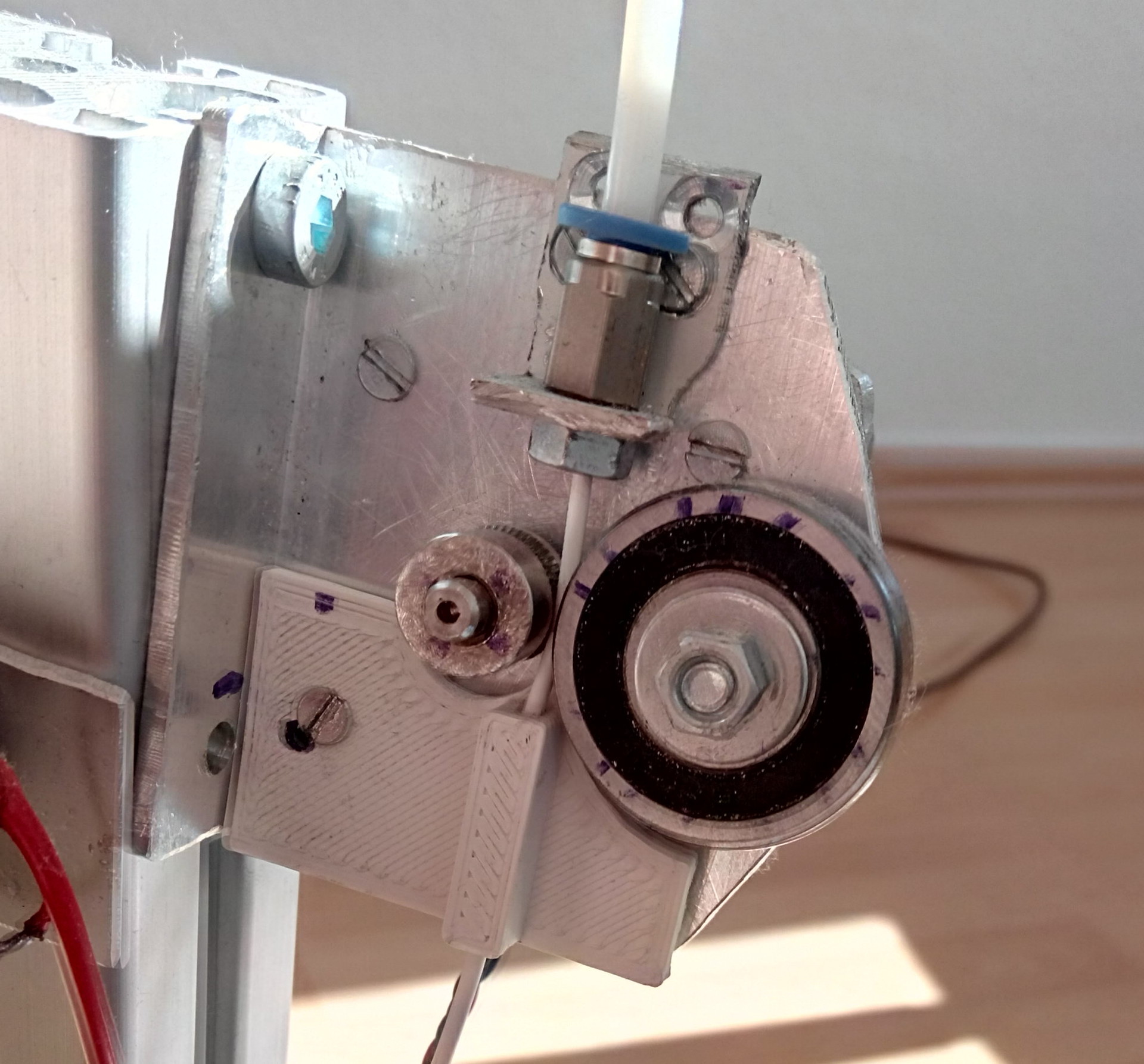
With the help of this prototype a working version was made:
My fantasy sometimes hits the fountain, and in the outlines of the plastic part I saw a butterfly.
The extruder has acquired the proud name of the Schmetterling Extruder. Looks like a title for some Rammstein song.
I have already quoted the video of this version in a publication about hot end:
Scheme of construction (I really love

It seems to me that this picture needs no explanation. Bolt for fixing the bearing: M7 or M8, the main thing - a fairly flat hex or square head. Depending on the internal diameter of the bearing, a thick sleeve may be necessary to prevent play between the bolt and the bearing. Without a sleeve, everything will hang out, no tightening will help. Why is the bearing so big (outside diameter 30 mm)? This is due to the design of the NEMA17 stepper motors, they have a protruding ring on the front flange, which does not allow the bolt head to move closer to the axis.
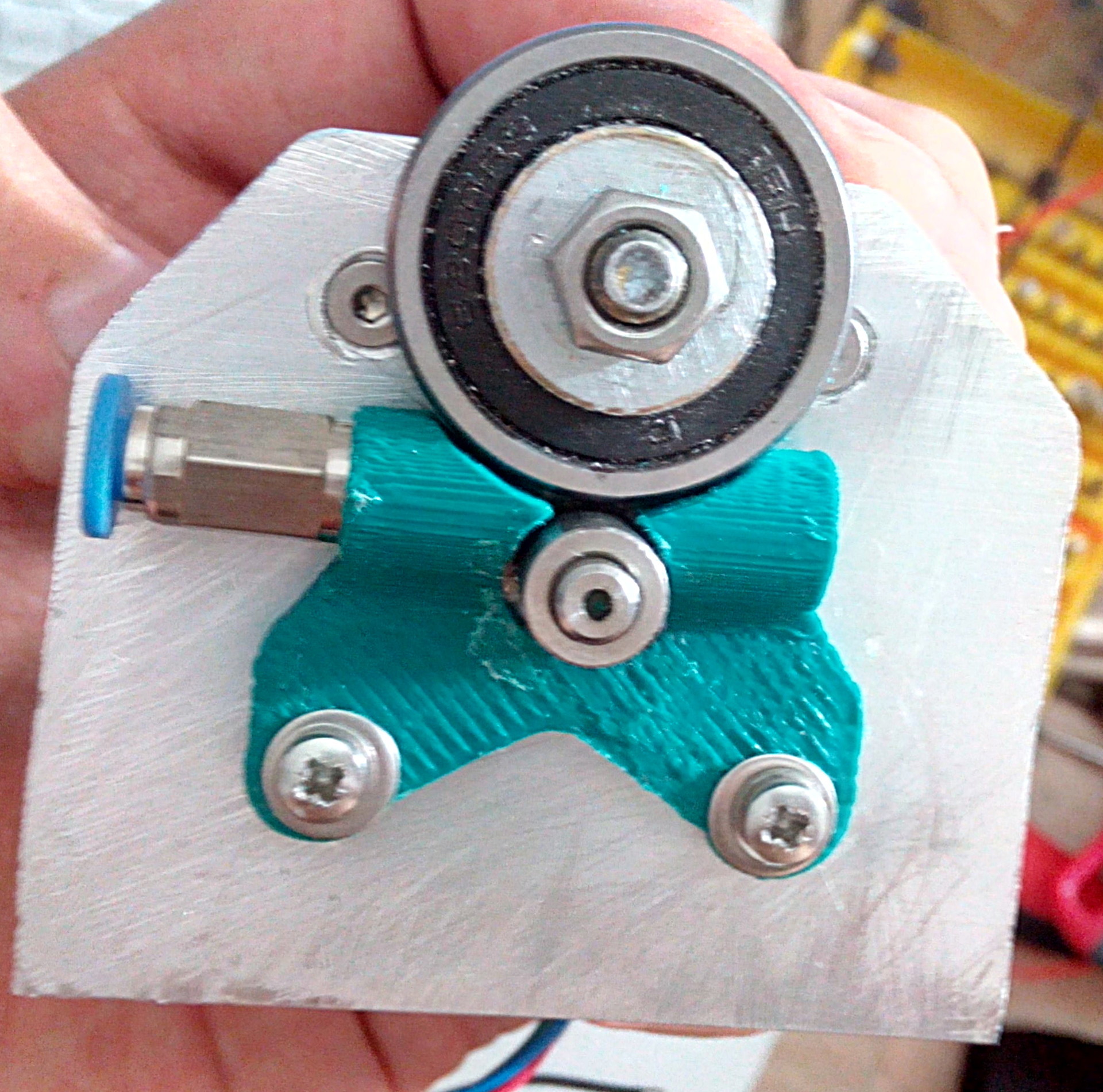
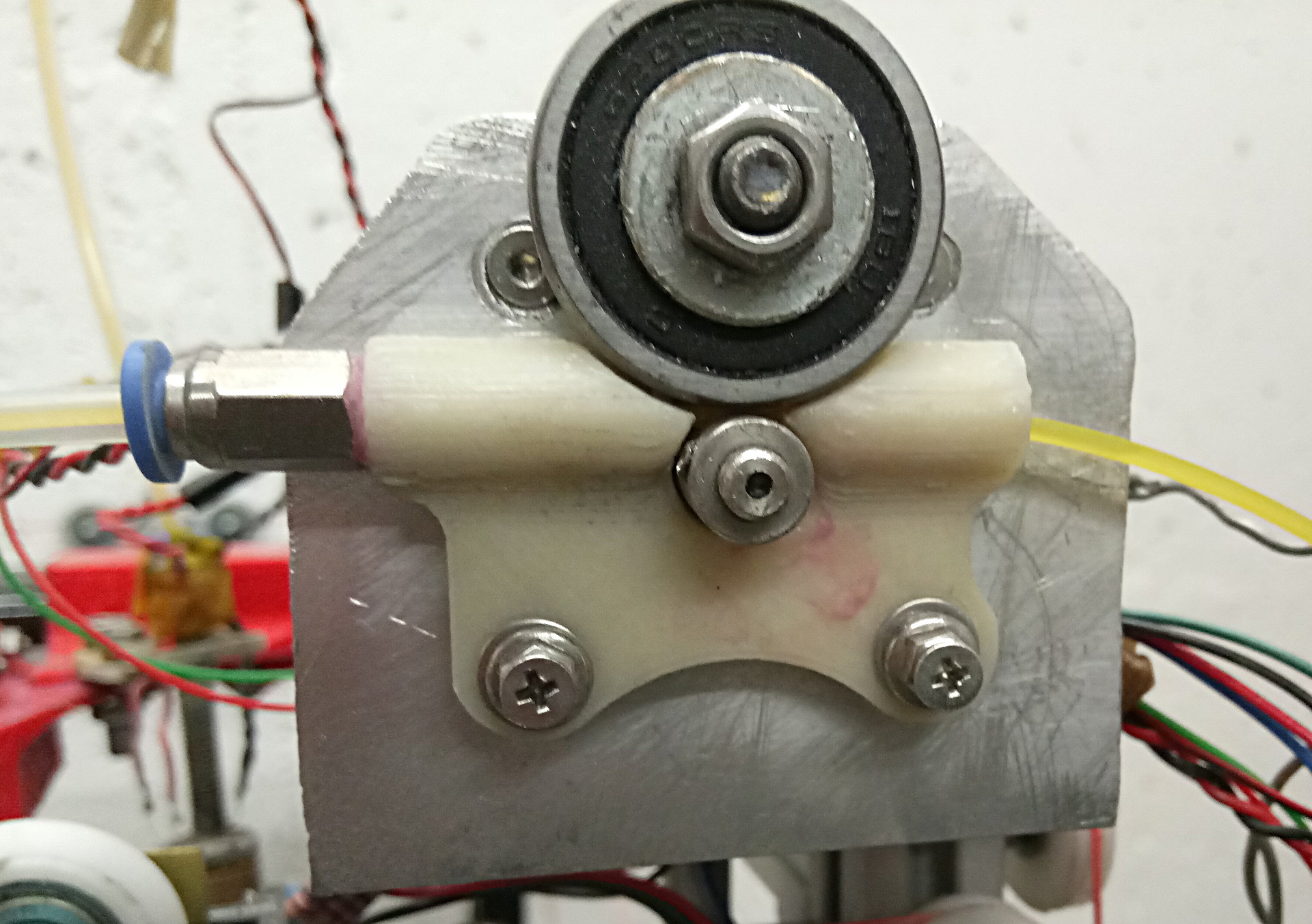
After that, quite a lot of water flowed, the butterfly's entrance channel wiped endless filament meters, and an improved version was created:
Since it is not interesting to have an extruder and not to print, I type. For example, the body for the Chinese audio DAC from PETG printed. Why does he need me? The laptop in the workshop completely refuses to produce sound through the standard connector, the motherboard has partially died out. I buy greedily for new, and it was interesting to try a separate DAC.
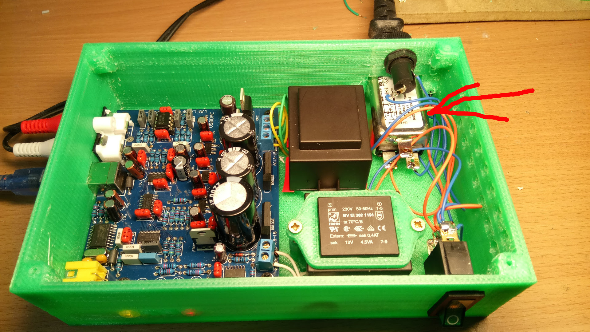
The red arrow shows the power harmonizer. Of course, many will say that this power harmonizer is very similar to a simple inexpensive (2-3 euro in Germany) surge protector with inductances and condensers, but we all know the truth: only magic with a price of two kiloboxes can provide power for the device to create a sound worthy of the delicate ears of all kinds of audio addicts.
The magnificent laurels of the myth-destroyers do not give me rest, and I decided to conduct tests. And not just tests, but tests of fractal diffusers. The extruder never hinted, and the diffusers came out just wonderful:

The yellow color hints at the little gold and thus underlines the premiumness and elitism of the product. Frankly, I did not expect such a powerful effect: when installing the diffuser on the DAC lid, the sound changes so dramatically that it seems that another person sings. This is magic, gentlemen. The video confirms the effect:
To enhance the effect of the use of diffusers, I installed self-printed spikes on the bottom of the case. The effect is obvious: at last, the flies that are firmly sitting on the table have ceased to create the “booze” effect in the columns. In order to finally make sure of the highest quality of spikes, we put a car on the device:
It is seen that the thorns withstood the test. Of course, the car is a toy, so the thorns are from PETG (it was impossible to get anoptanium).
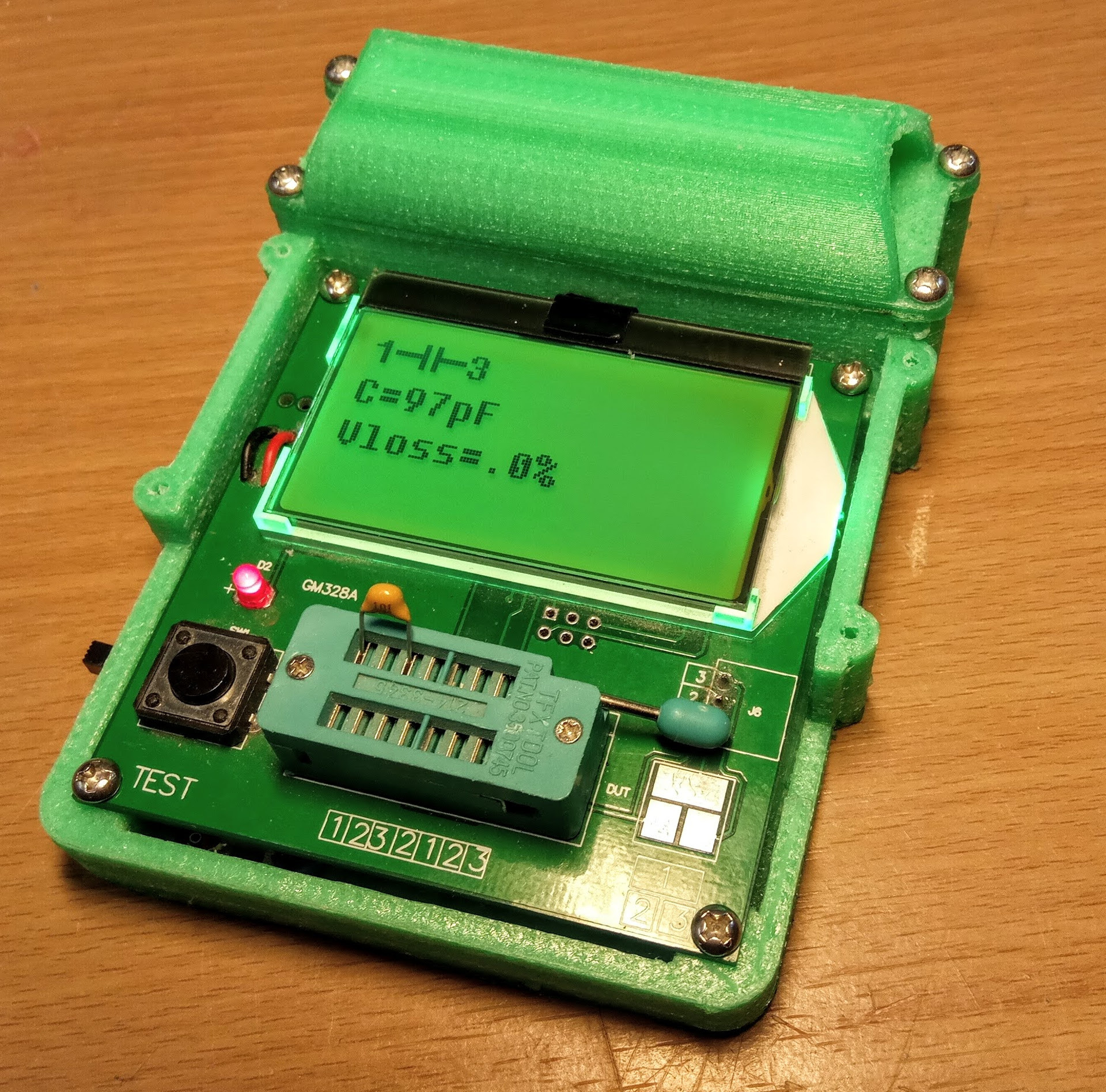
A small bonus for those who have read this far, a convenient body for the popular GM328 tester:
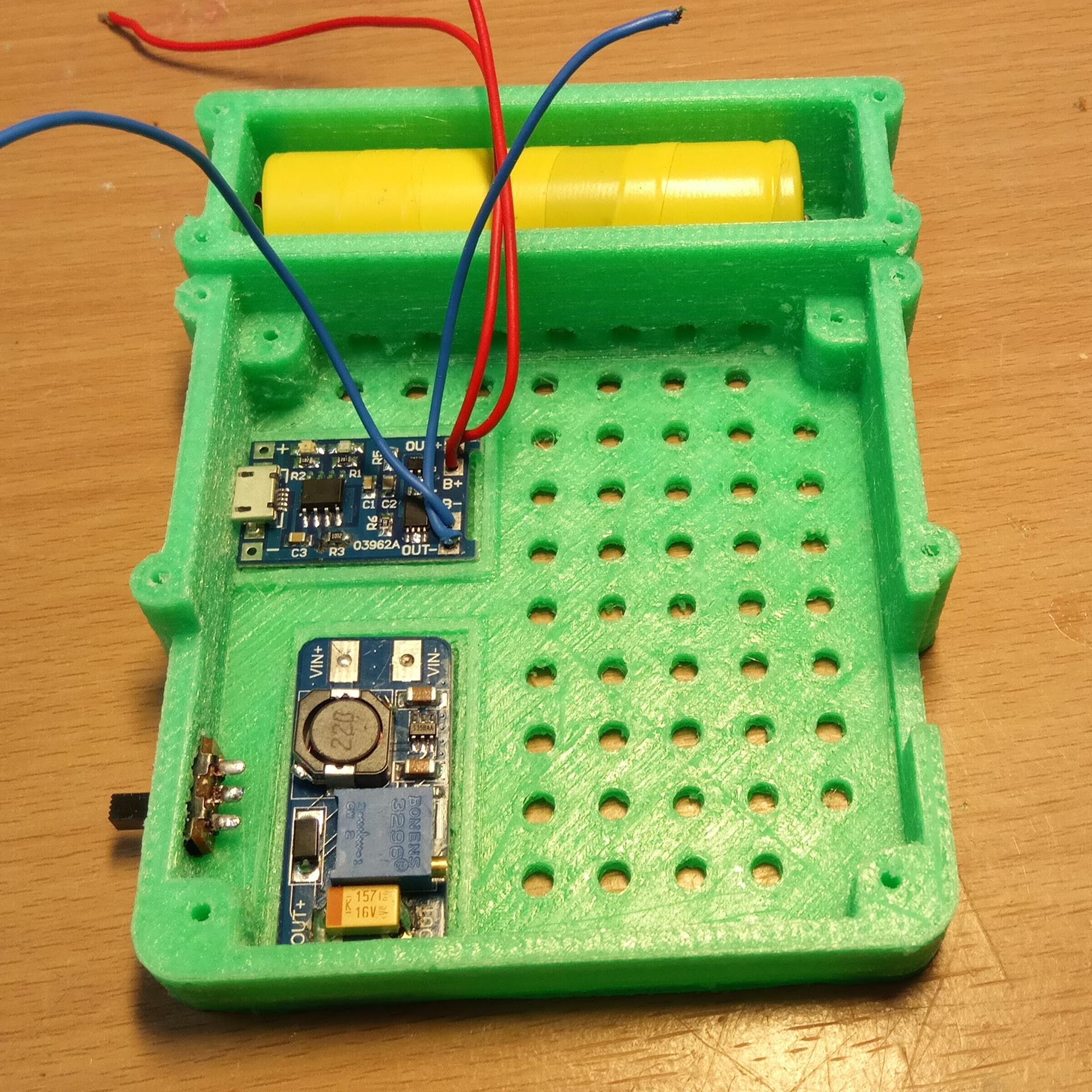
The battery charge control module and the boost converter (the tester operates at a voltage of 9V) are glued to specially designated places.
→ Here is a folder with 3D models.
Published under the WTFPL license.
Well, and traditional: Have fun!
Source: https://habr.com/ru/post/401871/
All Articles