Quadcopter on MultiWii SE v2.5 - from idea to first flight
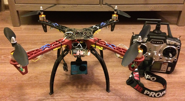
Some time ago, when I came across articles and videos about copters on the Internet, I thought it was difficult and not accessible to everyone. But the desire to become a copterovod was great and, after studying the mass of material on this topic, he concluded for himself that it was necessary to build a quadrocopter, namely buildings from scratch and himself, I did not want to buy the finished version. Now I want to share with you my experience of building a quadrocopter on MultiWii SE v2.5. In this article I will try to describe in detail the whole process of building a quadrocopter from scratch to the first flight to an absolute newcomer in this topic, as it was some time ago.
A little theory about flying quadrocopter
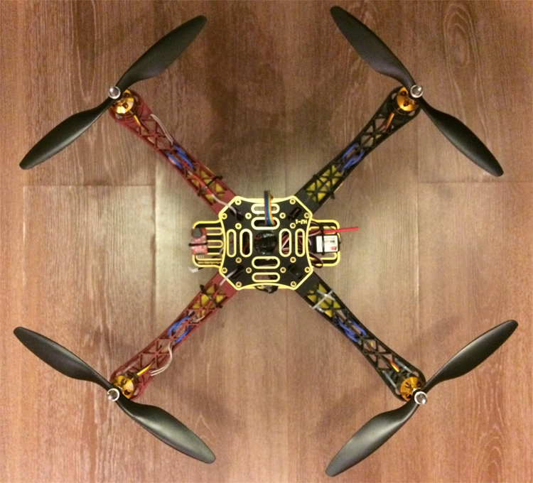
We will assemble a kopter on a classical frame of the form "X". Driving a copter is not as easy as it may seem at first glance, it does not have a front and backside like in radio-controlled cars. With the “forward” command, the quadrocopter flies not where the pilot is looking, but where the quadcopter's nose is directed (there is a corresponding arrow on the flight controller), this is a great danger for beginners, since from the ground, it is difficult to determine where the nose of the copter is, so when building it you need to somehow mark it, for example, with rays of a different color or placement of LEDs. Manage copter, i.e. define and set its orientation in space, we will be angles of pitch, roll and yaw + climb. The flight of the copter in the desired direction is achieved by changing these three angles. For example, in order to fly forward, the copter must bend its nose to the ground (pitch).
')

Required components:
Optional:
Assembly scheme:

Before assembly, it is necessary to calibrate the ESC regulators, the process is as follows: we connect the motor to the regulator, connect the regulator to the gas channel on the receiver (CH3) and to the battery, raise the gas stick on the control equipment up to the stop, turn on the appu - a characteristic sound is released, lower the gas stick up to the stop - a characteristic sound is made, then we test - we raise / lower the gas stick - we check the work, we turn off the app - the regulator is calibrated; by this analogy, we calibrate all ESC (suitable video for clarity).
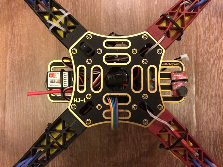
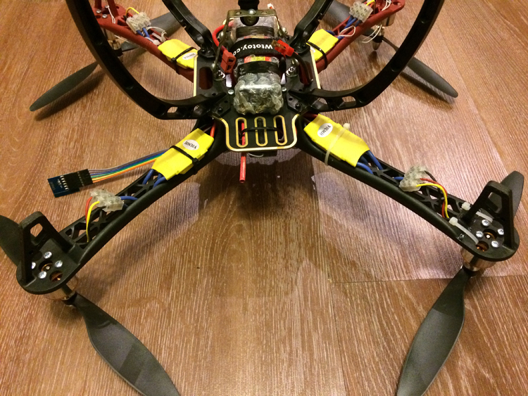
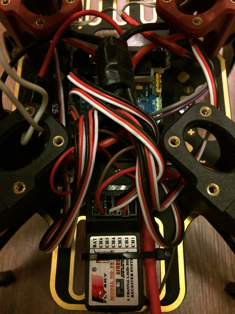
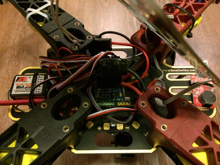
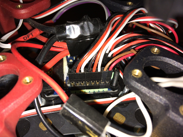
We assemble the frame, install MultiWii, fasten the motors, connect the ESC regulators: to the motors, to the MultiWii and to the batteries (we connect the pros and cons of the regulators to each other and connect them to the “+” and “-” battery). Attention, to change the direction of rotation of the motor, you just need to swap any two wires from the three leading from the motor to the ESC. It is desirable to install MultiWii on the frame through the platform (I did it myself , but you can buy it) in order to avoid short circuits to the case and for accuracy of the data; I also made a small “collective farm” for the barometer - I closed it with foam rubber to reduce the error in the data.
Additional channels CH5 and CH6 can be used to enable functions: hold height, return home, camera suspension control, etc., you can read more in this article . My diodes are connected to “+” and “-” on A2. The FTDI programmer is connected to the corresponding FTDI connector on the board.


After we have collected and connected everything, you need to upload the firmware to MultiWii, you need to do this through the Arduino IDE program (you can download the current version here ). We connect MultiWii to PC via FTDI programmer, launch the Arduino IDE, select the COM port to which the board is connected from the menu, choose the board type in the menu, open the firmware (link at the end of the article), open the MultiWii.ino file, you will see above several tabs, we will be interested only in config.h, in it we need to configure the firmware - depending on the required settings, you need to uncomment (delete “//”) one of the lines in the necessary section (link to the config.h file with my settings at the end articles), after setting we upload the firmware in MultiWii.
Now we need to continue setting up the kopter through the GUI, for this we will use the MultiWiiConf program (link at the end of the article). We connect MultiWii to PC via FTDI programmer, launch MultiWiiConf, select COM port to which the board is connected from the menu, press the START button (values should appear on the graph), before editing the parameters, click READ, to save the parameters, click WRITE. After you have selected the port and pressed START (you saw that the graph came to life, the data is coming), you need to calibrate the sensors: to calibrate the accelerometer - set the copter parallel to the horizon and press the CALIB_ACC button, the GUI will briefly hang, after that make sure that the ROLL and PITCH axes are parallel ; to calibrate the magnetometer (compass) - press the CALIB_MAG button and rotate the rotor on all axes or alternately place the rotor on the ribs for 30 seconds. Also, after successfully connecting the configurator program with your copter, on the top right you will see blue bars showing the channels of your console, move the sticks to make sure that everything is working correctly. The stick in the min position should show a value of 1000, in the center 1500 and at max 2000; if this is not the case, frame the remote according to its instructions (link at the end of the article). Remember that the stripes should move in accordance with the movements of the sticks, i.e. if you raise the throttle stick up, then the strip should go up (similarly for other channels), if this is not the case, reverse the channels of your console. Also in the GUI, you can set the functions to add. channels, such as height retention (BARO). The leveling horizon (LEVEL) function must be on all the time! Here is a suitable video for visibility of the MultiWiiConf program.
Several digressions on the topic
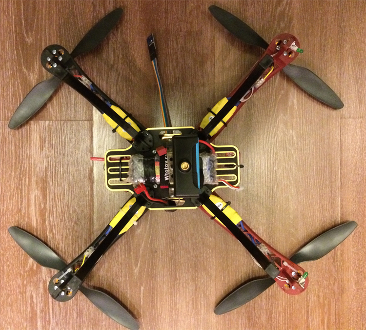
Do not wait for the function of holding height (BARO) hard hovering at the point, because for this, a barometer is used - the copter will certainly try to keep the altitude at which you activated the function, but it will float within a radius of ± a couple of meters, just for accuracy of the data from the barometer and for its protection from external influences I did a “collective farm” with foam rubber. Remember, height hold must be activated on hover gas, i.e. then, when you have achieved with a stick of gas that the kopter is kept at the same height and after activating the function it is not advisable to touch the gas. For a more accurate hovering at a point, it is better to use an additional GPS module.
The course hold function (MAG) is very capricious and its use ended pitifully for me, after activation and takeoff, the kopter began to rotate like a top and flew away from me quickly, attempts to detect the nose of the kopter and return it to the course were unsuccessful, I had no choice how to throw gas and run towards a point falling from the sky. Here is a small video and photo after the fall. Maybe this behavior was caused not by an exactly calibrated compass or magnetic interference, or something else; In general, read the information on the Internet before use and be careful.
For the future, it may be useful to you not to carry a laptop with the MultiWiiConf program with you — you can connect the HC-05 Bluetooth module to the MultiWii controller (connects to the UART connector) and via Android applications ( MultiWii Configuration and EZ-GUI Ground Station ) via Bluetooth connects to the copter, and make the necessary settings, similar to those in MultiWiiConf.
The procedure for starting the motors is as follows: turn on the power on the copter (squeak), turn on the app, pull the gas out of the lower position to the right - the motors are started (unset) and rotate at idle, now in order to take off smoothly add gas; in order to stop the motors, move the gas stick from the lower position to the left - the motors stopped, turn off the power on the copter, turn off the appu.
That's all, I hope my article will be useful to you, and now you can install propellers and go ahead, in our case up, good luck to you and fewer drops.
A small video of my flights
Download links:
Archive - MultiWii firmware + MultiWiiConf program
The config.h file with my settings
Manual FlySky FS-T6
A little theory about flying quadrocopter
We will assemble a kopter on a classical frame of the form "X". Driving a copter is not as easy as it may seem at first glance, it does not have a front and backside like in radio-controlled cars. With the “forward” command, the quadrocopter flies not where the pilot is looking, but where the quadcopter's nose is directed (there is a corresponding arrow on the flight controller), this is a great danger for beginners, since from the ground, it is difficult to determine where the nose of the copter is, so when building it you need to somehow mark it, for example, with rays of a different color or placement of LEDs. Manage copter, i.e. define and set its orientation in space, we will be angles of pitch, roll and yaw + climb. The flight of the copter in the desired direction is achieved by changing these three angles. For example, in order to fly forward, the copter must bend its nose to the ground (pitch).
')
Throttle - gas, climb
Aileron - Roll Steering Wheel, Aileron (roll)
Elevator - elevator, pitch (pitch)
Rudder - rudder, yaw (yaw)
Motors:
LFW - Left Front, Clockwise Rotation
RFC - right front, counterclockwise rotation
LBC - left rear, counterclockwise rotation
RBW - right rear, clockwise rotation
Required components:
Flight Controller CRIUS MultiWii SE v2.5
FTDI Programmer
Frame hj450
Motors 2212-1000KV - 4 pcs.
Speed controllers ESC 30A - 4 pcs.
Akkum 11.1V 2200Mah 3S 40C Li-Po ( example )
Battery Charger B3 AC 2S-3S 7.4V 11.1V Li-Po Battery Balancer
T-Plug Battery Wire
Plastic hose clamps
Control equipment FlySky FS-T6 2.4G 6CH complete with receiver
Propellers 1045 (10x4.5) CW / CCW - 2 pcs. clockwise rotation + 2pcs. counterclockwise rotation; take more propellers, because until you learn how to operate the copter, when falling, they will break on time
Optional:
Landing legs
Li-Po Battery Voltage Indicator Tester Low Voltage Tester (will signal when the battery is low)
Assembly scheme:
Before assembly, it is necessary to calibrate the ESC regulators, the process is as follows: we connect the motor to the regulator, connect the regulator to the gas channel on the receiver (CH3) and to the battery, raise the gas stick on the control equipment up to the stop, turn on the appu - a characteristic sound is released, lower the gas stick up to the stop - a characteristic sound is made, then we test - we raise / lower the gas stick - we check the work, we turn off the app - the regulator is calibrated; by this analogy, we calibrate all ESC (suitable video for clarity).
We assemble the frame, install MultiWii, fasten the motors, connect the ESC regulators: to the motors, to the MultiWii and to the batteries (we connect the pros and cons of the regulators to each other and connect them to the “+” and “-” battery). Attention, to change the direction of rotation of the motor, you just need to swap any two wires from the three leading from the motor to the ESC. It is desirable to install MultiWii on the frame through the platform (I did it myself , but you can buy it) in order to avoid short circuits to the case and for accuracy of the data; I also made a small “collective farm” for the barometer - I closed it with foam rubber to reduce the error in the data.
| Motors | MultiWii | Receiver | MultiWii |
| P.L. | D3 | CH1 | D4 |
| P.P. | D10 | CH2 | D5 |
| Z.L. | D11 | Ch3 | D2 |
| Z.P. | D9 | CH4 | D6 |
| CH5 (add. Channel) | D8 | ||
| CH6 (ext. Channel) | D7 |
Additional channels CH5 and CH6 can be used to enable functions: hold height, return home, camera suspension control, etc., you can read more in this article . My diodes are connected to “+” and “-” on A2. The FTDI programmer is connected to the corresponding FTDI connector on the board.
After we have collected and connected everything, you need to upload the firmware to MultiWii, you need to do this through the Arduino IDE program (you can download the current version here ). We connect MultiWii to PC via FTDI programmer, launch the Arduino IDE, select the COM port to which the board is connected from the menu, choose the board type in the menu, open the firmware (link at the end of the article), open the MultiWii.ino file, you will see above several tabs, we will be interested only in config.h, in it we need to configure the firmware - depending on the required settings, you need to uncomment (delete “//”) one of the lines in the necessary section (link to the config.h file with my settings at the end articles), after setting we upload the firmware in MultiWii.
Now we need to continue setting up the kopter through the GUI, for this we will use the MultiWiiConf program (link at the end of the article). We connect MultiWii to PC via FTDI programmer, launch MultiWiiConf, select COM port to which the board is connected from the menu, press the START button (values should appear on the graph), before editing the parameters, click READ, to save the parameters, click WRITE. After you have selected the port and pressed START (you saw that the graph came to life, the data is coming), you need to calibrate the sensors: to calibrate the accelerometer - set the copter parallel to the horizon and press the CALIB_ACC button, the GUI will briefly hang, after that make sure that the ROLL and PITCH axes are parallel ; to calibrate the magnetometer (compass) - press the CALIB_MAG button and rotate the rotor on all axes or alternately place the rotor on the ribs for 30 seconds. Also, after successfully connecting the configurator program with your copter, on the top right you will see blue bars showing the channels of your console, move the sticks to make sure that everything is working correctly. The stick in the min position should show a value of 1000, in the center 1500 and at max 2000; if this is not the case, frame the remote according to its instructions (link at the end of the article). Remember that the stripes should move in accordance with the movements of the sticks, i.e. if you raise the throttle stick up, then the strip should go up (similarly for other channels), if this is not the case, reverse the channels of your console. Also in the GUI, you can set the functions to add. channels, such as height retention (BARO). The leveling horizon (LEVEL) function must be on all the time! Here is a suitable video for visibility of the MultiWiiConf program.
Several digressions on the topic
Do not wait for the function of holding height (BARO) hard hovering at the point, because for this, a barometer is used - the copter will certainly try to keep the altitude at which you activated the function, but it will float within a radius of ± a couple of meters, just for accuracy of the data from the barometer and for its protection from external influences I did a “collective farm” with foam rubber. Remember, height hold must be activated on hover gas, i.e. then, when you have achieved with a stick of gas that the kopter is kept at the same height and after activating the function it is not advisable to touch the gas. For a more accurate hovering at a point, it is better to use an additional GPS module.
The course hold function (MAG) is very capricious and its use ended pitifully for me, after activation and takeoff, the kopter began to rotate like a top and flew away from me quickly, attempts to detect the nose of the kopter and return it to the course were unsuccessful, I had no choice how to throw gas and run towards a point falling from the sky. Here is a small video and photo after the fall. Maybe this behavior was caused not by an exactly calibrated compass or magnetic interference, or something else; In general, read the information on the Internet before use and be careful.
For the future, it may be useful to you not to carry a laptop with the MultiWiiConf program with you — you can connect the HC-05 Bluetooth module to the MultiWii controller (connects to the UART connector) and via Android applications ( MultiWii Configuration and EZ-GUI Ground Station ) via Bluetooth connects to the copter, and make the necessary settings, similar to those in MultiWiiConf.
The procedure for starting the motors is as follows: turn on the power on the copter (squeak), turn on the app, pull the gas out of the lower position to the right - the motors are started (unset) and rotate at idle, now in order to take off smoothly add gas; in order to stop the motors, move the gas stick from the lower position to the left - the motors stopped, turn off the power on the copter, turn off the appu.
That's all, I hope my article will be useful to you, and now you can install propellers and go ahead, in our case up, good luck to you and fewer drops.
A small video of my flights
Download links:
Archive - MultiWii firmware + MultiWiiConf program
The config.h file with my settings
Manual FlySky FS-T6
Source: https://habr.com/ru/post/401789/
All Articles