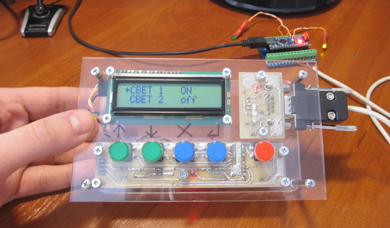
Operator Panel (HMI) with I2C Bus for Arduino
As part of working with some kind of arduino-compatible equipment (about him at the end) I needed a screen with buttons to control and display current information. That is, the operator panel was needed, it is HMI.
It was decided to make the HMI independently, and use the “square” i2c bus as the interface.
')
If you are interested in the process of developing and programming such devices, welcome to Cat.
Specifications:
There will be obvious questions:


1. Homemade interconnect board with DB9F connector. So, as we take + 5V power supply for port and display extenders, we take it from Arduino, put a fuse 0.1 A on the board.
2. We all know the well-known 1602 display with a soldered FC-113 board, which connects the display to the i2c bus.
3. A homemade keyboard card with a PCF8574P microchip that will read the states of the buttons and transfer them over the i2c bus. By the way, the FC-113 “display” board is also based on the PCF8574 chip, only with the T index, i.e. planar, not DIP, like PCF8574P.
I put the buttons 12x12mm with a square pusher; you can put on them large multi-colored caps.
It should say a few words about the PCF8574P microcircuit, on the basis of which I made a keyboard board.
PCF8574P is a port extender with i2c interface. In total there are 8 ports, each of which can be configured to work as an input or output. For this chip and strapping as such is not required (remember, for example, max232), I just in case put a capacitor on the power supply.
The address of the PCF8574P chip is set using the address legs A0, A1, A2, which pull to the ground or to the power through a 10 kΩ resistor.
On the keyboard board, I put all the address feet of the PCF8574P on the ground, so the address is hard-coded as 0x20 and cannot be changed.
As I already wrote, I chose the DB9F as the connector for the HMI. Arduino receives signals from it +5 V, GND, SDA, SCL.

The wire for communication on i2c Arduino and HMI made 1.4 m long, works without glitches.
He drew the boards in Sprint Layout 6, transferred it by LUT to textolite and etched it in a solution of peroxide and citric acid.
The body made a friend of plexiglass 4 mm on a laser cutting machine.
From the point of view of Arduino, this HMI consists of 2 devices that operate on the i2c bus: a display (LCD) with the address 0x27 and a keyboard with the address 0x20. Accordingly, the Arduino will work separately with the keyboard and separately with the LCD.
Work with LCD is carried out through a special library "LiquidCrystal_I2C.h", it must be installed in the Aduino IDE.
The keyboard is handled through the standard Wire.h library, which is originally available in the Aduino IDE.
Connect HMI to Ardiuno.

1. First, check to see if Arduino sees our HMI. To do this, we load into it a program that will scan the i2c bus for the presence of devices on it.
During the execution of this program, Arduino will write the i2c bus scan results to the serial port. To view this data, go to Tools-> Port Monitor in the Arduino IDE.

We see that Arduino on the i2c bus has identified two devices with addresses 0x20 and 0x27, this is the keyboard and LCD, respectively.
2. Now let's see how our keyboard works. Create a program that will poll the state of the buttons and display it on the LCD.

The keyboard works.
3. Finally, you can move on to what it was all about — the creation of a multi-level menu in Arduino. Through the menu we will not only look at the information, but also manage the outputs of the Arduino itself.

Nete has a lot of information on creating a multi-level menu in C ++, and for Arduino I even saw some libraries. But I decided in my program to write the menu myself. First, the smaller the left libraries in the project, the calmer. And secondly, it's easy.
I got another variation of the tree menu. The menu allows you to display in each line both static text and a variable value. For example, you can display the name of the parameter and its value.
To display variables on the screen, I apply the principle of tags - in a certain way decorated text labels in the text, instead of which, when the text is displayed, a value is displayed on the screen.
Parameters can be changed by pressing the “Edit” button. Moreover, the tag of each parameter indicates whether it is available for editing or only for reading. If the current parameter is read-only, at the beginning of the line the pointer will be '*', if editing the parameter is allowed, the pointer will become '+'.
Separately, you need to address the issue of Russification.
In the character generator of some LCD 1602, there are no Russian letters, and instead of them, Japanese cracks are stitched. Reflash character generator is not possible. Therefore, it is necessary either to write words on the screen in Latin letters, or in the program to form Russian letters yourself, since LCD 1602 has the ability to create and store your own characters in the LCD RAM. But, in the latter case, you can display no more than eight “homemade” characters at a time.
In principle, there is nothing terrible if you write Russian words in LCD in English letters. Vaughn, even the venerable French company Shneider Electric (the same one that sold howitzers to the king before the revolution) for a decade and a half did not allow herself to introduce Russian into their famous Zelio programmable relays. But this does not prevent them from actively trading in the entire CIS. Moreover, the channel, Spanish and Portuguese have entered.
At many of our factories, these Zelio communicate with staff with phrases like “NASOS 1 VKL”.
When it is unclear whether there are Russian letters in a particular LCD, you need to display all the characters of its character generator. If there is a Cyrillic alphabet, it begins with the 160 position.
But even if your LCD 1602 is Russified, displaying Russian words is not so easy. At least using the “LiquidCrystal_I2C.h” library when working with LCDs on the i2c bus.
If you simply display the Russian text, for example, the lcd.print instruction (“Hello !!!”), then instead of “Hello !!!” some sort of rubbish will appear on the screen.
This is because the Arduino IDE translates the Russian letters into a two-byte UTF-8 code, and in the LCD all the characters are single-byte.
The same problem, by the way, is observed when transferring Russian texts from Arduino to the monitor of the Arduino IDE port. Arduino transmits Russian letters in a two-byte UTF-8 encoding to the serial port, and the Arduino IDE port monitor attempts to read them in the single-byte Windows-1251 encoding (cp1251). Although cp1251 is also 8-bit, like the LCD encoding 1602, but it does not match.
You can create Russian texts through character codes. For example, the line "LCD display" on the Russified LCD will be displayed as follows:
But I do not like this approach.
In order to correctly display the Russian text on the Russified LCD 1602, several libraries were invented for Arduino. But after reading the reviews, I saw that many complain about glitches when using them.
Therefore, in my multi-level menu program I myself wrote a simple function to transform UTF-8 into LCD codes. True, he did it only for the capital Russian letters, which suits me perfectly.
On this about homemade HMI with i2c bus, I have everything.
Oh yeah, at the beginning of the article I wrote that I was doing HMI not entirely for Arduino, but for arduino-compatible equipment. This is me about the CONTROLLINO MAXI PLC, which is programmed from the Arduino IDE (and many others).

CONTROLLINO MAXI is actually an Arduino + a bunch of shields and everything is designed as an industrial PLC. But about him next time.
Links
→ Archive with layouts, sketches and a printed circuit board in lay6 format
→ Arduino-compatible PLC CONTROLLINO , work with which inspired the creation of the HMI i2c
→ Port Expander PCF8574 and connect it to Arduino
→ FC-113 board for running LCD 1602 over i2c bus and connecting it to Arduino
→ Multi-level tree menu , general principles of creation in C
→ UTF-8 Encoding
→ Encoding Windows-1251
It was decided to make the HMI independently, and use the “square” i2c bus as the interface.
')
If you are interested in the process of developing and programming such devices, welcome to Cat.
Specifications:
- Display 1602, monochrome 16x2 characters
- 5 buttons: up, down, cancel, enter, edit
- I2c interface
- DB9F Connector
- Dimensions 155x90x44 mm
There will be obvious questions:
Why not buy ready shild?
Of course, it was possible for the same Chinese to buy a ready-made shield with a display and keyboard and the type of this:

To this shield you can solder 2 FC-113 scarves and it will functionally the same as mine: a display with a keyboard, working on i2c. Price set from $ 4.
But on this board, the size of the buttons does not suit me, but I wanted big ones, with the ability to install multi-colored caps. I wanted to connect the Arduino to the HMI not on snot, but through a normal DB9F connector, which means it was necessary to make a connection board. And in this case, what's the difference, to make one board or two? In addition, I already had a few 1602 displays in stock, and therefore I only needed to spend $ 1.02 to buy the FC-113 board ($ 0.55) and the PCF8574P port extender ($ 0.47) on Aliexpress.
Well, and most importantly, if you are dealing with Arduino, then making shields yourself is a matter of course for him, right?
Why bus i2c, is not it easier to connect the buttons directly?
In the field of automated process control systems where I work, HMIs use RS-232, RS-485, CAN, etc. interfaces to communicate with devices. Therefore, it is logical for me that my self-made HMI will all work on the data interface, in this case on i2c.
If I had made a device where the display runs on a square bus, and the buttons go directly to the Arduino entrance, this would give me a feeling of deep dissatisfaction. How to present this picture: from the panel sticks out a separate lace on the interface, separate wires at the entrance, brrrr ...
In addition, the difference between the button board, which goes directly to the Arduino inputs, and the button board with the i2c interface, is only in the PCF8574P chip ($ 0.47), a capacitor, and two resistors.
Why are the buttons located so and not otherwise?
The buttons on my left to right have the following functions: up, down, cancel, enter, edit.
The “edit” button is moved away from the rest slightly to emphasize its function — changing the values of logical parameters (on / off) or switching to editing mode in the case of numeric parameters.
Total buttons 5, although the chip on the keyboard board allows you to connect up to 8 pieces.
It would be enough to do with four buttons and the functionality would not hurt, “input” and “editing” can be combined in one button. But I just felt sorry that half of the 8 legs of the port extender chip will not be used.
Another separate “editing” button can be useful if I decide to display several parameters on one line. Then this button will be able to switch between the parameters, indicating which one needs to be changed. This is how the SET button works in the popular Chinese HMI OP320.
If the first two buttons mean up and down, then why not place them vertically, as, for example, done in the above Chinese shield?
For me personally, it is more convenient when all the buttons are horizontally, then during operation, the fingers move only in one plane.
Iron
1. Homemade interconnect board with DB9F connector. So, as we take + 5V power supply for port and display extenders, we take it from Arduino, put a fuse 0.1 A on the board.
2. We all know the well-known 1602 display with a soldered FC-113 board, which connects the display to the i2c bus.
3. A homemade keyboard card with a PCF8574P microchip that will read the states of the buttons and transfer them over the i2c bus. By the way, the FC-113 “display” board is also based on the PCF8574 chip, only with the T index, i.e. planar, not DIP, like PCF8574P.
I put the buttons 12x12mm with a square pusher; you can put on them large multi-colored caps.
Photos and homemade circuit boards


It should say a few words about the PCF8574P microcircuit, on the basis of which I made a keyboard board.
PCF8574P is a port extender with i2c interface. In total there are 8 ports, each of which can be configured to work as an input or output. For this chip and strapping as such is not required (remember, for example, max232), I just in case put a capacitor on the power supply.
The address of the PCF8574P chip is set using the address legs A0, A1, A2, which pull to the ground or to the power through a 10 kΩ resistor.
On the keyboard board, I put all the address feet of the PCF8574P on the ground, so the address is hard-coded as 0x20 and cannot be changed.
As I already wrote, I chose the DB9F as the connector for the HMI. Arduino receives signals from it +5 V, GND, SDA, SCL.
The wire for communication on i2c Arduino and HMI made 1.4 m long, works without glitches.
He drew the boards in Sprint Layout 6, transferred it by LUT to textolite and etched it in a solution of peroxide and citric acid.
Little about etching
There are many recipes for etching citric acid boards on foiled fiberglass laminate online.
I made such a solution: 100 ml of hydrogen peroxide 3%, 50 g of citric acid, 3 teaspoons of salt. A jar of peroxide was heated in a saucepan with water to a temperature of about 70 degrees.
We immerse the board in the solution by drawing down, as recommended by etching with peroxide.
After a couple of tens of seconds, the rapid process begins. There is a lot of steam, which is not recommended to inhale. Probably.

Then the process subsides. Turn over the board.

Is done.

I made such a solution: 100 ml of hydrogen peroxide 3%, 50 g of citric acid, 3 teaspoons of salt. A jar of peroxide was heated in a saucepan with water to a temperature of about 70 degrees.
We immerse the board in the solution by drawing down, as recommended by etching with peroxide.
After a couple of tens of seconds, the rapid process begins. There is a lot of steam, which is not recommended to inhale. Probably.
Then the process subsides. Turn over the board.
Is done.
The body made a friend of plexiglass 4 mm on a laser cutting machine.
Lyrical digression about the corps
Buy a finished case or do it yourself? A little thought, I decided to do it myself. Those that I saw on sale did not suit me either for the price, or for aesthetic reasons, or were on a DIN-rail, which also did not suit me.
Initially, the body wanted to cut out of plywood. But then I remembered that I have a wonderful friend and, for my great joy, the director of the company for the production of sports awards. He has all sorts of machines there, including for laser cutting.
I asked for help and my friend did not refuse; in a couple of minutes the laser cut the parts.
Taking this opportunity, I want to say, thank you, Kolya! Otherwise, I would have to cut and grind plywood for a whole day, and the result would hardly have been so brilliant.
Programming
From the point of view of Arduino, this HMI consists of 2 devices that operate on the i2c bus: a display (LCD) with the address 0x27 and a keyboard with the address 0x20. Accordingly, the Arduino will work separately with the keyboard and separately with the LCD.
Work with LCD is carried out through a special library "LiquidCrystal_I2C.h", it must be installed in the Aduino IDE.
The keyboard is handled through the standard Wire.h library, which is originally available in the Aduino IDE.
Connect HMI to Ardiuno.
1. First, check to see if Arduino sees our HMI. To do this, we load into it a program that will scan the i2c bus for the presence of devices on it.
Sketch 1, i2c tire scan
//i2c_scaner #include <Wire.h> String stringOne; void setup() { Wire.begin(); Serial.begin(9600); while (!Serial); } void loop() { byte error, address; int nDevices; Serial.println("Scanning..."); nDevices = 0; for(address = 1; address < 127; address++ ) { Wire.beginTransmission(address); error = Wire.endTransmission(); if (error == 0) { String stringOne = String(address, HEX); Serial.print("0x"); Serial.print(stringOne); Serial.print(" - "); if(stringOne=="0A") Serial.println("'Motor Driver'"); if(stringOne=="0F") Serial.println("'Motor Driver'"); if(stringOne=="1D") Serial.println("'ADXL345 Input 3-Axis Digital Accelerometer'"); if(stringOne=="1E") Serial.println("'HMC5883 3-Axis Digital Compass'"); if(stringOne=="5A") Serial.println("'Touch Sensor'"); if(stringOne=="5B") Serial.println("'Touch Sensor'"); if(stringOne=="5C") Serial.println("'BH1750FVI digital Light Sensor' OR 'Touch Sensor" ); if(stringOne=="5D") Serial.println("'Touch Sensor'"); if(stringOne=="20") Serial.println("'PCF8574 8-Bit I/O Expander' OR 'LCM1602 LCD Adapter' "); if(stringOne=="21") Serial.println("'PCF8574 8-Bit I/O Expander'"); if(stringOne=="22") Serial.println("'PCF8574 8-Bit I/O Expander'"); if(stringOne=="23") Serial.println("'PCF8574 8-Bit I/O Expander' OR 'BH1750FVI digital Light Sensor'"); if(stringOne=="24") Serial.println("'PCF8574 8-Bit I/O Expander'"); if(stringOne=="25") Serial.println("'PCF8574 8-Bit I/O Expander'"); if(stringOne=="26") Serial.println("'PCF8574 8-Bit I/O Expander'"); if(stringOne=="27") Serial.println("'PCF8574 8-Bit I/O Expander' OR 'LCM1602 LCD Adapter '"); if(stringOne=="39") Serial.println("'TSL2561 Ambient Light Sensor'"); if(stringOne=="40") Serial.println("'BMP180 barometric pressure sensor'" ); if(stringOne=="48") Serial.println("'ADS1115 Module 16-Bit'"); if(stringOne=="49") Serial.println("'ADS1115 Module 16-Bit' OR 'SPI-to-UART'"); if(stringOne=="4A") Serial.println("'ADS1115 Module 16-Bit'"); if(stringOne=="4B") Serial.println("'ADS1115 Module 16-Bit'"); if(stringOne=="50") Serial.println("'AT24C32 EEPROM'"); if(stringOne=="53") Serial.println("'ADXL345 Input 3-Axis Digital Accelerometer'"); if(stringOne=="68") Serial.println("'DS3231 real-time clock' OR 'MPU-9250 Nine axis sensor module'"); if(stringOne=="7A") Serial.println("'LCD OLED 128x64'"); if(stringOne=="76") Serial.println("'BMP280 barometric pressure sensor'"); if(stringOne=="77") Serial.println("'BMP180 barometric pressure sensor' OR 'BMP280 barometric pressure sensor'"); if(stringOne=="78") Serial.println("'LCD OLED 128x64'" ); nDevices++; } else if (error==4) { Serial.print("Unknow error at address 0x"); if (address<16) Serial.print("0"); Serial.println(address,HEX); } } if (nDevices == 0) Serial.println("No I2C devices found\n"); else Serial.println("done\n"); delay(5000); } During the execution of this program, Arduino will write the i2c bus scan results to the serial port. To view this data, go to Tools-> Port Monitor in the Arduino IDE.
We see that Arduino on the i2c bus has identified two devices with addresses 0x20 and 0x27, this is the keyboard and LCD, respectively.
2. Now let's see how our keyboard works. Create a program that will poll the state of the buttons and display it on the LCD.
Sketch 2, displaying the status of buttons
/* LCD i2c LCD FC-113, 0x27 PCF8574P, 0x20 */ #include <LiquidCrystal_I2C.h> #include <Wire.h> #define led 13 #define ADDR_KBRD 0x20 #define ADDR_LCD 0x27 byte dio_in; bool b; bool key[5]; LiquidCrystal_I2C lcd(ADDR_LCD,16,2); // void setup() { pinMode(led, OUTPUT); // lcd.init(); lcd.backlight();// // Wire.begin(); Wire.beginTransmission(ADDR_KBRD); Wire.write(B11111111); // PCF8574P Wire.endTransmission(); } void loop() { Wire.requestFrom(ADDR_KBRD,1); while (!Wire.available()); byte dio_in = Wire.read(); // PCF8574P() // byte mask=1; for(int i=0; i<5;i++) { key[i]=!(dio_in & mask); mask=mask<<1; } b=!b; digitalWrite(led, b); // // LCD lcd.setCursor(0, 0); lcd.print(String(key[0])+" "+ String(key[1])+" "+ String(key[2])+" "+ String(key[3])+" "+ String(key[4])+" "); delay(100); } The keyboard works.
3. Finally, you can move on to what it was all about — the creation of a multi-level menu in Arduino. Through the menu we will not only look at the information, but also manage the outputs of the Arduino itself.
Nete has a lot of information on creating a multi-level menu in C ++, and for Arduino I even saw some libraries. But I decided in my program to write the menu myself. First, the smaller the left libraries in the project, the calmer. And secondly, it's easy.
I got another variation of the tree menu. The menu allows you to display in each line both static text and a variable value. For example, you can display the name of the parameter and its value.
To display variables on the screen, I apply the principle of tags - in a certain way decorated text labels in the text, instead of which, when the text is displayed, a value is displayed on the screen.
Parameters can be changed by pressing the “Edit” button. Moreover, the tag of each parameter indicates whether it is available for editing or only for reading. If the current parameter is read-only, at the beginning of the line the pointer will be '*', if editing the parameter is allowed, the pointer will become '+'.
Sketch 3, multi-level menu
/* , LCD i2c LCD FC-113, 0x27 PCF8574P, 0x20 */ #include <LiquidCrystal_I2C.h> #include <Wire.h> #define led 13 // ; , , #define ADDR_KBRD 0x20 #define ADDR_LCD 0x27 #define PORT_D2 2 #define PORT_D3 3 #define PORT_D4 4 #define POINT_ON_ROOT_MENU_ITEM 0 // 0/1= / (* +) byte dio_in; bool b; byte i; //bool , bool BoolVal[9]={0,0,0, 0,0,0, 0,0,0}; #define ValSvet1 BoolVal[0] #define ValSvet2 BoolVal[1] #define ValSvet3 BoolVal[2] #define ValRozetka1 BoolVal[3] #define ValRozetka2 BoolVal[4] #define ValRozetka3 BoolVal[5] #define ValClapan1 BoolVal[6] #define ValClapan2 BoolVal[7] #define ValClapan3 BoolVal[8] // struct STRUCT_KEY{ bool StateCur; // bool StateOld; // bool Imp; // ( 0 1) }; // STRUCT_KEY Key[5]={0,0,0, 0,0,0, 0,0,0, 0,0,0, 0,0,0 }; //--- /* * , : * '#A1' bool , * '#'- bool, * 'A'- (HEX) BoolVal, * '1'- * , */ String StrNull=" "; // String StrRoot1="COMP-MAN.INFO"; String StrRoot2="PLC-BLOG.COM.UA"; String StrSvet= ""; // String StrSvet1=" 1 #01"; String StrSvet2=" 2 #10"; String StrSvet3=" 3 #21"; String StrRozetka=""; // String StrRozetka1=" 1 #30"; String StrRozetka2=" 2 #40"; String StrRozetka3=" 3 #50"; String StrClapan=""; // String StrClapan1=" 1 #60"; // String StrClapan2=" 2 #70"; String StrClapan3=" 3 #80"; struct MENU_ITEM // (), 2 { byte KeyUp; //№ , "" byte KeyDwn; //№ , "" byte KeyCancel; //№ , ""(cancel) byte KeyEnter; //№ , ""(enter) byte KeyEdit; // "edit", String *pstr1; // () String *pstr2; // () }; // MENU_ITEM Menu[]={0,0,0,1,0, &StrRoot1,&StrRoot2, //0 1,8,0,2,0, &StrSvet,&StrRozetka, //1 2,3,1,2,0, &StrSvet1,&StrSvet2, //2 2,4,1,3,0, &StrSvet2,&StrSvet3, //3 3,4,1,4,0, &StrSvet3,&StrNull, //4 0,0,0,0,0, &StrNull,&StrNull, //5 0,0,0,0,0, &StrNull,&StrNull, //6 0,0,0,0,0, &StrNull,&StrNull, //7 1,15,0,9,0, &StrRozetka,&StrClapan, //8 9,10,8,9,0, &StrRozetka1, &StrRozetka2, //9 9,11,8,10,0, &StrRozetka2, &StrRozetka3, //10 10,11,8,11,0, &StrRozetka3, &StrNull, //11 0,0,0,0,0, &StrNull,&StrNull, //12 0,0,0,0,0, &StrNull,&StrNull, //13 0,0,0,0,0, &StrNull,&StrNull, //14 8,15,0,16,0, &StrClapan, &StrNull, //15 16,17,15,0,0, &StrClapan1,&StrClapan2, //16 16,18,15,0,0, &StrClapan2,&StrClapan3, //17 17,18,15,0,0, &StrClapan3,&StrNull, //18 0,0,0,0,0, &StrNull,&StrNull, //19 0,0,0,0,0, &StrNull,&StrNull, //20 0,0,0,0,0, &StrNull,&StrNull, //21 }; byte PosMenu=0; // LiquidCrystal_I2C lcd(ADDR_LCD,16,2); // // void ReadKey(byte dio_in) { // byte mask=1; for(i=0; i<5; i++) { Key[i].StateCur=!(dio_in & mask); mask=mask<<1; Key[i].Imp=!Key[i].StateOld & Key[i].StateCur; // ( 0 1) Key[i].StateOld=Key[i].StateCur; } } /* * UTF-8 ( ) LCD * */ byte MasRus[33][2]= { 144, 0x41, // 145, 0xa0, 146, 0x42, 147, 0xa1, 148, 0xe0, 149, 0x45, 129, 0xa2, 150, 0xa3, 151, 0xa4, 152, 0xa5, 153, 0xa6, 154, 0x4b, 155, 0xa7, 156, 0x4d, 157, 0x48, 158, 0x4f, 159, 0xa8, 160, 0x50, 161, 0x43, 162, 0x54, 163, 0xa9, 164, 0xaa, 165, 0x58, 166, 0xe1, 167, 0xab, 168, 0xac, 169, 0xe2, 170, 0xad, 171, 0xae, 172, 0xc4, 173, 0xaf, 174, 0xb0, 175, 0xb1 // }; String RusStrLCD(String StrIn) { String StrOut=""; byte b1; byte y; byte l=StrIn.length(); for(byte i=0; i<l; i++) { b1=StrIn.charAt(i); if (b1<128) StrOut=StrOut+char(b1); else { if (b1==208) //==208, 2- . { b1=StrIn.charAt(i+1); for(y=0; y<33; y++) if(MasRus[y][0]==b1) { StrOut=StrOut+char(MasRus[y][1]); break; } } i++; } } return StrOut; } //--------------------------- //ASCII HEX ---> dec byte StrHexToByte(char val) { byte dec=0; switch (val) { case '0': dec=0; break; case '1': dec=1; break; case '2': dec=2; break; case '3': dec=3; break; case '4': dec=4; break; case '5': dec=5; break; case '6': dec=6; break; case '7': dec=7; break; case '8': dec=8; break; case '9': dec=9; break; case 'A': dec=10; break; case 'B': dec=11; break; case 'C': dec=12; break; case 'D': dec=13; break; case 'E': dec=14; break; case 'F': dec=15; break; default: dec=0; break; } return dec; } // void WriteLCD(byte num) { String str[]={"*"+*Menu[num].pstr1,*Menu[num].pstr2}; if (num==0 && POINT_ON_ROOT_MENU_ITEM==0) // ? str[0].setCharAt(0,' '); // , // byte NumVal; byte l; for(byte y=0; y<2; y++) { l=str[y].length(); for(i=0; i<l; i++) { if (str[y].charAt(i)=='#') //# bool, off/ON { if(StrHexToByte(str[y].charAt(i+2))==1 && y==0) // ? str[y].setCharAt(0,'+'); NumVal=StrHexToByte(str[y].charAt(i+1)); str[y]=str[y].substring(0,i)+String(NumVal) ; if(BoolVal[NumVal]==0) str[y]=str[y].substring(0,i)+"off" ; if(BoolVal[NumVal]==1) str[y]=str[y].substring(0,i)+"ON" ; } if (str[y].charAt(i)=='$') //$ int, , { ; } if (str[y].charAt(i)=='~') //~ , , { ; } } } //--- lcd.clear(); lcd.setCursor(0, 0); lcd.print(str[0]); lcd.setCursor(1, 1); lcd.print(str[1]); } //, byte GoMenu(byte key) { byte PosMenuNew=PosMenu; switch (key) { case 0: PosMenuNew=Menu[PosMenu].KeyUp; break; case 1: PosMenuNew=Menu[PosMenu].KeyDwn; break; case 2: PosMenuNew=Menu[PosMenu].KeyCancel; break; case 3: PosMenuNew=Menu[PosMenu].KeyEnter; break; case 4: ; break; default: break; } return PosMenuNew; } // "Edit" void Edit(byte posmenu) { byte NumVal; bool *pval; String str=*Menu[posmenu].pstr1; byte l=str.length(); for(i=0; i<l; i++) if (str.charAt(i)=='#') //#- bool, off/ON { if(StrHexToByte(str.charAt(i+2))==1) // ? { pval= &(BoolVal[StrHexToByte(str.charAt(i+1))]); // , . *pval=!(*pval); // } } } // void ValToPort() { digitalWrite(PORT_D2,ValSvet1); digitalWrite(PORT_D3,ValSvet2); digitalWrite(PORT_D4,ValSvet3); } void setup() { pinMode(led, OUTPUT); // pinMode(PORT_D2, OUTPUT); pinMode(PORT_D3, OUTPUT); pinMode(PORT_D4, OUTPUT); // LCD StrSvet=RusStrLCD(StrSvet); StrSvet1=RusStrLCD(StrSvet1); StrSvet2=RusStrLCD(StrSvet2); StrSvet3=RusStrLCD(StrSvet3); StrRozetka=RusStrLCD(StrRozetka); StrRozetka1=RusStrLCD(StrRozetka1); StrRozetka2=RusStrLCD(StrRozetka2); StrRozetka3=RusStrLCD(StrRozetka3); StrClapan=RusStrLCD(StrClapan); StrClapan1=RusStrLCD(StrClapan1); StrClapan2=RusStrLCD(StrClapan2); StrClapan3=RusStrLCD(StrClapan3); // lcd.init(); lcd.backlight();// WriteLCD(PosMenu); Wire.begin(); Wire.beginTransmission(ADDR_KBRD); Wire.write(B11111111); // PCF8574P Wire.endTransmission(); } void loop() { Wire.requestFrom(ADDR_KBRD,1); while (!Wire.available()); byte dio_in = Wire.read(); // PCF8574P() ReadKey(dio_in); // //, ; , int KeyImp=-1; for (i=0; i<5; i++) if(Key[i].Imp==1) { KeyImp=i; Key[i].Imp==0; } if (KeyImp>-1) // ? { if (KeyImp==4) // "Edit" Edit(PosMenu); PosMenu=GoMenu((KeyImp)); WriteLCD(PosMenu); } b=!b; digitalWrite(led, b); // ValToPort(); // delay(50); } LCD 1602 and language issue
Separately, you need to address the issue of Russification.
In the character generator of some LCD 1602, there are no Russian letters, and instead of them, Japanese cracks are stitched. Reflash character generator is not possible. Therefore, it is necessary either to write words on the screen in Latin letters, or in the program to form Russian letters yourself, since LCD 1602 has the ability to create and store your own characters in the LCD RAM. But, in the latter case, you can display no more than eight “homemade” characters at a time.
Character Charts LCD 1602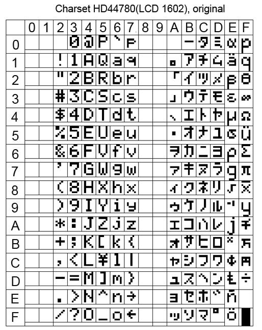

In principle, there is nothing terrible if you write Russian words in LCD in English letters. Vaughn, even the venerable French company Shneider Electric (the same one that sold howitzers to the king before the revolution) for a decade and a half did not allow herself to introduce Russian into their famous Zelio programmable relays. But this does not prevent them from actively trading in the entire CIS. Moreover, the channel, Spanish and Portuguese have entered.
At many of our factories, these Zelio communicate with staff with phrases like “NASOS 1 VKL”.
When it is unclear whether there are Russian letters in a particular LCD, you need to display all the characters of its character generator. If there is a Cyrillic alphabet, it begins with the 160 position.
Sketch 4, displaying all characters from the character generator LCD 1602 table
/* LCD * LCD i2c */ #include <LiquidCrystal_I2C.h> LiquidCrystal_I2C lcd(0x27,16,2); // void setup() { // put your setup code here, to run once: lcd.init(); lcd.clear(); } void loop() { int i,y; while(1) { for (i=0; i < 16; i++) { lcd.clear(); lcd.setCursor(0,0); lcd.print(String(i*16)+" - "+String(i*16+15)); lcd.setCursor(0,1); for(y=0;y<16;y++) lcd.print(char(i*16+y)); delay(3000); } } } But even if your LCD 1602 is Russified, displaying Russian words is not so easy. At least using the “LiquidCrystal_I2C.h” library when working with LCDs on the i2c bus.
If you simply display the Russian text, for example, the lcd.print instruction (“Hello !!!”), then instead of “Hello !!!” some sort of rubbish will appear on the screen.
This is because the Arduino IDE translates the Russian letters into a two-byte UTF-8 code, and in the LCD all the characters are single-byte.
The same problem, by the way, is observed when transferring Russian texts from Arduino to the monitor of the Arduino IDE port. Arduino transmits Russian letters in a two-byte UTF-8 encoding to the serial port, and the Arduino IDE port monitor attempts to read them in the single-byte Windows-1251 encoding (cp1251). Although cp1251 is also 8-bit, like the LCD encoding 1602, but it does not match.
You can create Russian texts through character codes. For example, the line "LCD display" on the Russified LCD will be displayed as follows:
lcd.print("\243K \343\270c\276\273e\271"); But I do not like this approach.
In order to correctly display the Russian text on the Russified LCD 1602, several libraries were invented for Arduino. But after reading the reviews, I saw that many complain about glitches when using them.
Therefore, in my multi-level menu program I myself wrote a simple function to transform UTF-8 into LCD codes. True, he did it only for the capital Russian letters, which suits me perfectly.
The function of converting capital Russian letters UTF-8 to single-byte code LCD 1602
/* * UTF-8 ( ) LCD * */ byte MasRus[33][2]= { 144, 0x41, // 145, 0xa0, 146, 0x42, 147, 0xa1, 148, 0xe0, 149, 0x45, 129, 0xa2, 150, 0xa3, 151, 0xa4, 152, 0xa5, 153, 0xa6, 154, 0x4b, 155, 0xa7, 156, 0x4d, 157, 0x48, 158, 0x4f, 159, 0xa8, 160, 0x50, 161, 0x43, 162, 0x54, 163, 0xa9, 164, 0xaa, 165, 0x58, 166, 0xe1, 167, 0xab, 168, 0xac, 169, 0xe2, 170, 0xad, 171, 0xae, 172, 0xc4, 173, 0xaf, 174, 0xb0, 175, 0xb1 // }; String RusStrLCD(String StrIn) { String StrOut=""; byte b1; byte y; byte l=StrIn.length(); for(byte i=0; i<l; i++) { b1=StrIn.charAt(i); if (b1<128) StrOut=StrOut+char(b1); else { if (b1==208) //==208, 2- . { b1=StrIn.charAt(i+1); for(y=0; y<33; y++) if(MasRus[y][0]==b1) { StrOut=StrOut+char(MasRus[y][1]); break; } } i++; } } return StrOut; } On this about homemade HMI with i2c bus, I have everything.
Oh yeah, at the beginning of the article I wrote that I was doing HMI not entirely for Arduino, but for arduino-compatible equipment. This is me about the CONTROLLINO MAXI PLC, which is programmed from the Arduino IDE (and many others).
CONTROLLINO MAXI is actually an Arduino + a bunch of shields and everything is designed as an industrial PLC. But about him next time.
Links
→ Archive with layouts, sketches and a printed circuit board in lay6 format
→ Arduino-compatible PLC CONTROLLINO , work with which inspired the creation of the HMI i2c
→ Port Expander PCF8574 and connect it to Arduino
→ FC-113 board for running LCD 1602 over i2c bus and connecting it to Arduino
→ Multi-level tree menu , general principles of creation in C
→ UTF-8 Encoding
→ Encoding Windows-1251
Source: https://habr.com/ru/post/401587/
All Articles