Tesla Electromechanical Coil
A couple of years ago, C0NTEMPLATOR came to me in St. Petersburg, he was delighted with the half-bridge DRSSTC that I had then, and expressed a desire to have such a miracle in my dacha to entertain guests. In general, this request was gradually forgotten, but one fine September day I had nothing to do and wanted something epic.
And I decided to build SGTC (Spark Gap Tesla Coil), because 1) the price of the components tends to zero 2) construction and debugging is simple and fun 3) the probability of error is minimal and does not threaten anything. Especially since I haven’t collected any normal coil on the spark gap before.
I will not describe the principles of operation of the resonant transformer and copy-paste the description of the generator in the spark gap so that the article seems smarter and more. Only materiel, only hardcore!
Part one - the body
')
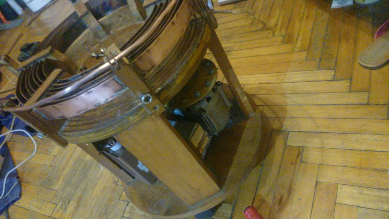
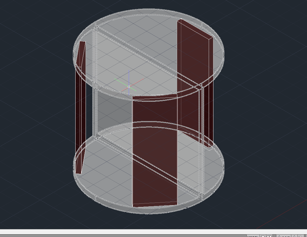
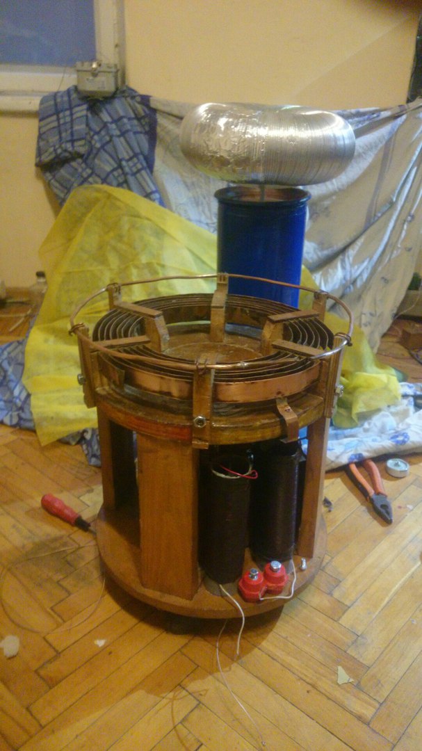
I will say right away - I already had a chassis from one of the old, and not finished projects. The most common option - take two Soviet round stools and break them, hehe. Further, if desired, fasten the seat of the stools with screws and some kind of mother. In the middle of the board height of 350mm, width in diameter, 15-20mm thick and three four boards around the circumference, in order to betray the design rigidity. For installation it is worth using corners for example and screws.
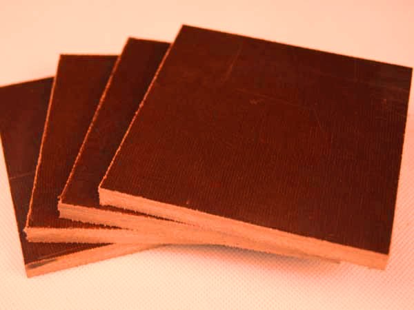
You can take not stools, and kosher thick electrotechnical PCB that installs panels in electrical cabinets, but it can cost you a lot of money if you don’t buy it from an electrician Vasya for a bottle.
Fastenings for the primary winding can be performed using a wooden bar 22x75, recalling the lessons of labor in school, hehe.
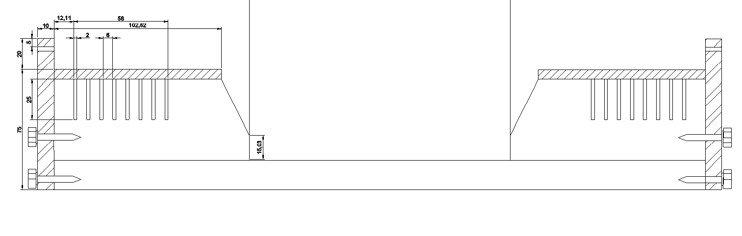
(yes, the weight of the lines for wimps, figs it knows why it was so converted, but readable like).
Part two. Installation of the primary.
It is better to make the winding itself from a 1.5 × 25mm wide copper bus; you can buy 8 meters for quite reasonable money.
1) We make 6 pieces of fasteners
2) We put them on epoxy (well, or on wood glue there for example) on the upper stool 3) take the tire, drill a hole on one side, fix a piece of copper wire 400 mm long with soldering, section from 25 squares.
3) We put the tire in 8 turns, starting from the center, removing the wire from the beginning through the hole in the upper seat of the former stool to the place where we will have a motor with a disk.
4) On top of the same epoxy we glue a wooden bar with a thickness of 10mm and wide and 22mm thickness for final fixation of the tire.
5) At the top of the strap, which is attached to two self-tapping screws, fasten with ties / wires \ what will have an unclosed circle from a copper tube.
6) Proffit!
Part Three Secondary winding.
We take the wire sew with a diameter of 0.5mm, take a sewer pipe with a diameter of 16 mm (orange such), we wind the coil to the coil until the height of the winding is 400 mm, we cover the resulting disgrace with epoxy in several layers. You can use the PELSHO wire in silk insulation (if you can find it, lol), the quality of the coil will decrease due to the increase in the distance between the turns, but the dielectric strength will increase, it is easier to coat it with epoxy, and after coating the coil looks cool. It all sounds easy, but without a lathe with small turns and preferably a smooth start long and hemorrhoids.
As a machine you can use your friend and mop, dy.
From above we insert a standard plug (alarm! You didn’t saw off the pipe extension to install the plug?), Make a hole in the plug (not a hole, but named a hole! With a soldering iron, yes), fasten an M6 pin through the washers, connect the upper end from below Wiring to the hairpin, then we twist the coil and fill the inside of the pipe with half a liter of epoxy, gee.
Bottom we solder the winding wire to the wire in silicone insulation of 300 mm long commercial, fasten through two holes, isolate, proffit.
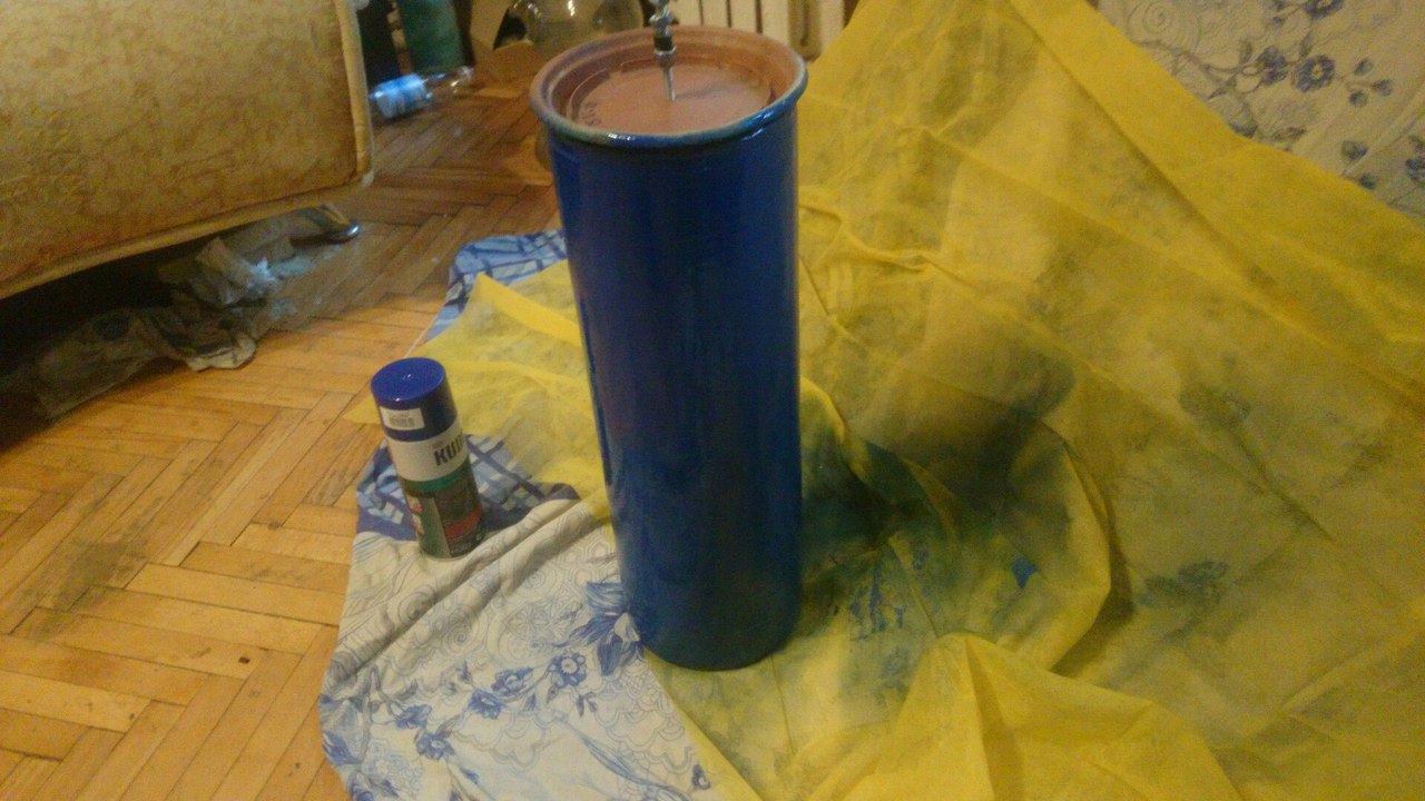
Monsieur also painted it with alkyd enamel from a can. Because he could. As it turned out, it was, ahem, odd, but more on that later.
Part Four Electrical installation.
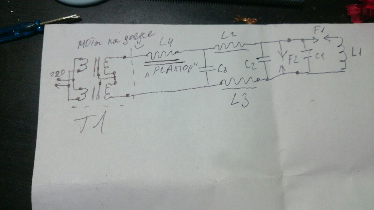
Cool, megapolyatnaya scheme of this high-tech device.
The most important part of the coil is, gee, the master oscillator, marked on the diagram as F2. It is made with the latest technology of the beginning of the 20th century. Structurally, it is an asynchronous motor of 2750 rev / min, on the shaft of which a textolite disk with a diameter of approx 130mm and a thickness of 8mm is fixed. At a distance of 10 mm from the edge of the disk, 12 holes were drilled into which brass pins were inserted, bolted on both sides.

Achtung! Alarm! Attension! Entrust the production of the disk to your uncle, otherwise you have a non-illusory chance to get a nut in the forehead. Or drive. Or more than that. On both sides of the disc are two copper electrodes. Structurally - just two bars crimped into tires, tires - bolted through insulators into the center plate, so that by loosening the bolts you can change the distance of the spark gap. Distance - the less the better. But so as not to beat. Ideally - less than a millimeter. The engine is connected via a condender directly to the network.
Next - MMC (literally stands for "many small capacitors"), C1 in the diagram. But the real guys use big capacitors and there are few of them, yes.
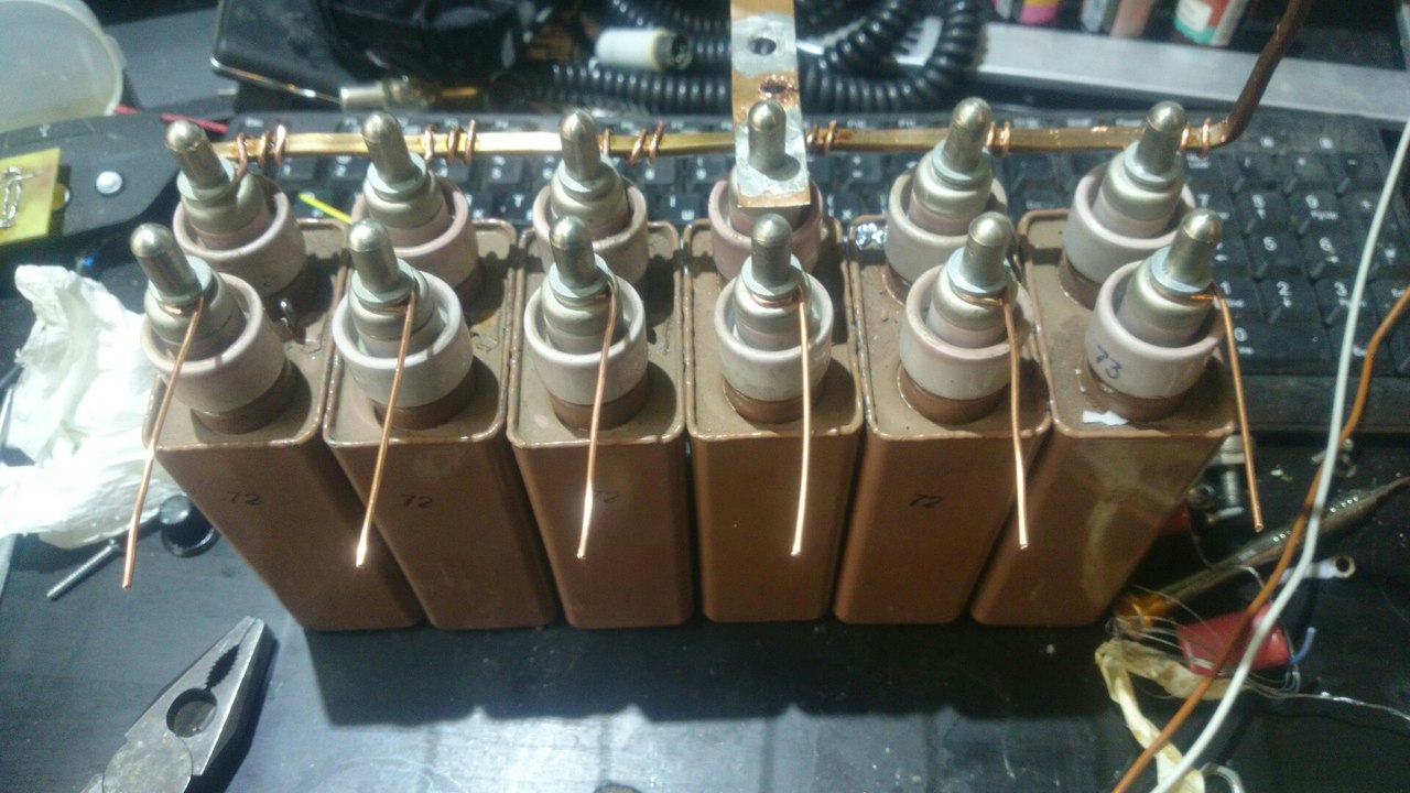
Personally, I used 6 pcs k75-25, 10kV, 10nF. A brief lyrical digression - in circuit C1 - L1, switched by the arrester, kiloampere currents walk in impulse, therefore postpone your wiring, username. Switching should be appropriate - the shortest possible connections, soldering tires with a soldering iron, bolted connections, wires of 25 squares and more. And the rest is already possible as it will have, but within reason.
Nutrition. Everything is simple - we break the mamkin’s microwave, habar at the neighbors and break another. Well, or honestly buy two BB transformers of them. We install two transformers on a common, preferably steel or not very bed, the main thing is to connect electrically the magnetic cores to which the cold end of the secondary winding of the transformers is connected. The resulting middle point - through the divider on film capacitors of 10-50 nF we throw on the network phase and zero, this will save ILOs from the effects of shocks of discharges into the case. A healthy network choke L4 at 6-8 H. Nafig is not needed if you do not feed the coil with rectified double voltage, as it adds little to the discharge, it is made long and gemmno (coil-to-coil, fluoroplastic / oil paper gaskets between layers), roll lot.
Filter chokes and tanks. In order to avoid any backflushing in the delicate secondary winding of transformers, we had to make two chokes of 500-600 turns each on the rim of a 50mm tube. Inside the tube stuffed broken ferrite. Also, before and after the ferrites, it is desirable to hang two 1000pF capacitors, some kind of disk KVI-3
Filter on otlichnenko climbed into the cabinet, where they and the place.
Part Five. Commissioning
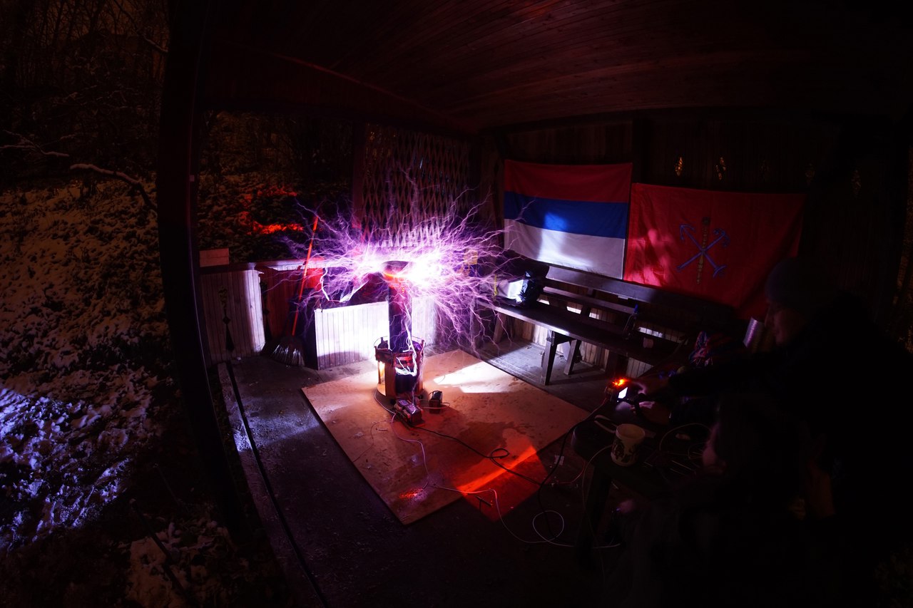
The design is almost ready, it remains only to make a torroid. Of course, I could have laid out the drawings of the corporate toroid named Zerg, but I'm afraid he will come to my house and kill my dog (although I don’t have a dog, but suddenly he will drag me!). So for example, it can be made from vent pipes with a diameter of 150mm and pull it from the top with a metal disk through a pin to the top of the secondary.
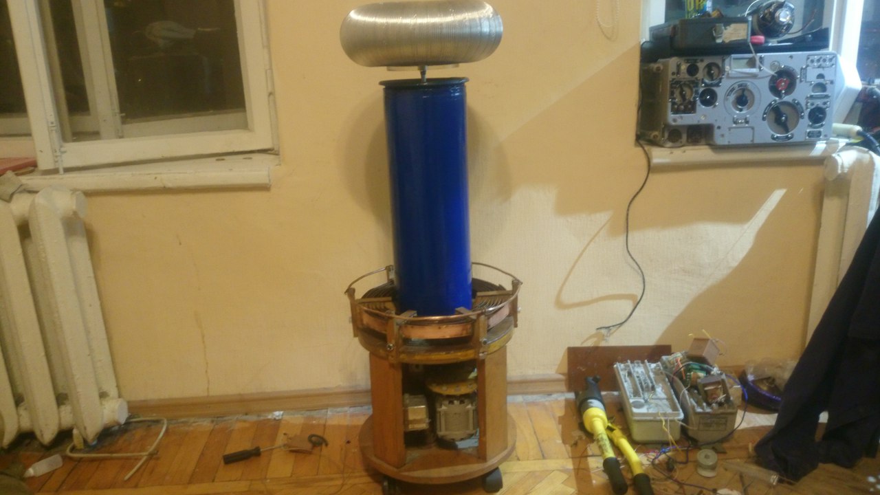
The result is this, sometimes even nice design. The lower outlet from the secondary coil in the silicone wire is passed under the coils of the primary and soldered to the discharge ring of a copper tube. From this ring, we lower the ground wire to be hung on good, usable earth.
The second bus from capacitors is to look for that turn of the secondary winding, when connected, the discharges are more powerful, I just connected it to the 6th turn and soldered so, relying on calculations.
And so we turn on the motor of the rotating discharger, check the absence of chatter and vibration, turn on the power.
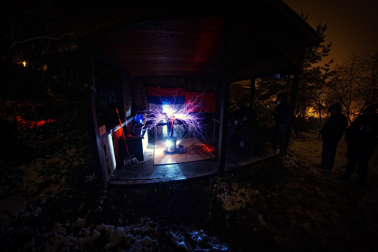
If everything is good, then the device will give usable, a couple of meters long, discharges with a very specific and loud noise. If not, check the phasing of the transformers, perhaps they are included in antiphase.
In theory, it was necessary to improve the transformer unit, to make automatic devices on the time relay to switch on the arrester, and only then supply voltage, but at that time I did not have normal relays (this thing eats from 2 to 4 kW for a sweet soul), and it was lazy.
Subsequently, the device was transported by me to MSC, presented, and from there to the cottage to the comrade, where it was reassembled and launched.

True, afterwards either wet weather or a fig cover of the secondary winding or just it burnt to hell and recently I had to fly out again to rewind the coil, and the old one was solemnly beaten to hell (in fact, no, just remove the epoxy using beats Board - very fig idea, lol)

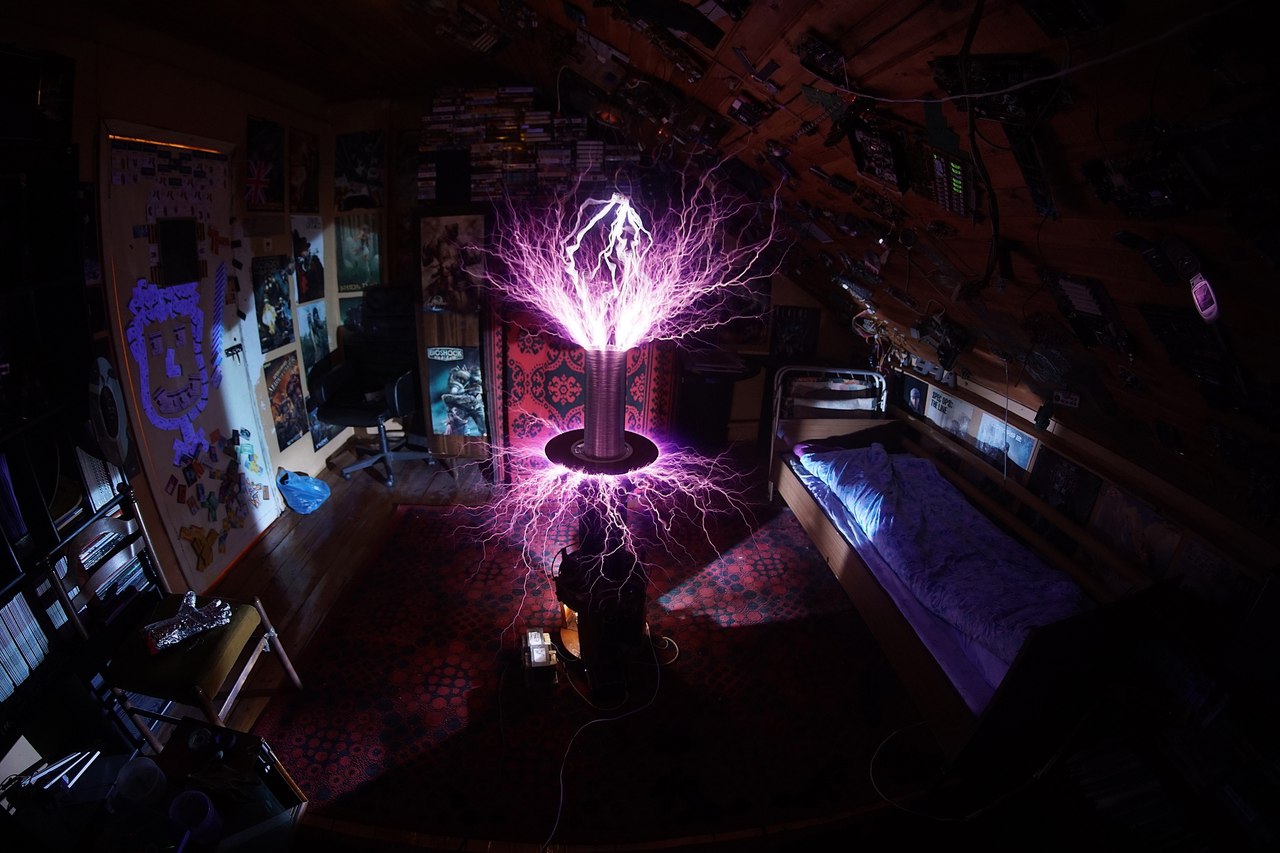
The device with the new coil still works successfully and pleases the comrade, who really shoves everything on the torroid, but sometimes it turns out to be fun.
Source: https://habr.com/ru/post/401467/
All Articles