How we made the biggest Tesla coil in Russia
History reference
The 19th century was the era of the wild West in experimental physics of electromagnetism. Robert Van de Graaf, Lord Kelvin, Nikola Tesla and many other scientists, researchers and engineers discovered more and more new phenomena, and then scaled their installations to enormous dimensions. Some of their creations are still in operation - for example, the six-meter giant Van de Graaff generator in the Boston Museum of Science , and some, like the well-known Wordencliffe tower, never came to light.

')
With the passage of time and the development of science and technology, the attention of scientists has shifted to other directions, but individual enthusiasts continued to collect, study and improve classical developments in the field of high voltages, electrostatics, plasma physics - someone due to unfading belief in the theory of the ether and free energy, who out of curiosity, or for solving highly specialized applied problems, someone simply because it delivered to him.
Recently, from about the end of the 1990s, this branch of engineering tasks has been experiencing a renaissance associated with the interest of show business and the entertainment industry to the attention-grabbing discharges of Tesla coils , which has intensified in the last decade since the invention of DRSSTC , which currently represents the most technically perfect type of Tesla coil, which uses power transistors instead of the classical spark gap, which allows quickly - during several periods of oscillations - to change the frequency of discharge ( BPS ) and, as a result, play music directly with the help of lightning. One example is the well-known serial model OneTesla, which, despite the lack of thoughtfulness of the designer proposed by the authors, is quite workable with a certain application of hands.
Currently, Tesla transformers and related devices (Jacob’s ladders, Marx and Cockroft-Walton generators, plasma columns, Van de Graaff generators, etc.) of various sizes and entertainment are used on a regular basis in a number of show projects organized around them in USA (Arc Attack), Russia (TeslaFX), Great Britain (Lords of Lightning), China (alas, not trained in hieroglyphs) and other countries, occasionally glow in show business (special effects in Harry Potter, The Sorcerer's Apprentice, Metallica concerts, etc. ), and also present as an exhibit Every self-respecting science museum.
Size matters
In short, at one point a group of amateur engineers, long and firmly immersed in the collective teslastroenie, decided that they were playing in the sandbox, doing small indoor (and even mid-size street) coils, they were already bored, and decided to do something special. At that time, we already had (as it seemed to us) enough experience in the development of Tesla coils of various topologies and the existing mathematical model allowed for the scaling of a typical construction several times. In fact, the only clearly visible restrictions were the dimensions of the available room, the outlet power, and finances (although, what is there, in the end, everything depends on finances). Having estimated the budget, man-hours and other boring trifles, it was decided to limit the installation to about three meters in height, with an estimated power of about 30-40 kW. For those who understand the question:
Summary specifications
- Technology: DRSSTC
- Overall height: 3.3 meters
- Total weight: ~ 130 kg
- Power supply: 3F 380 V
- Resonant frequency: ~ 50 kHz
- Secondary winding dimensions: 3101800 mm, wire 1.06 mm
- The power unit topology: full bridge, transistors CM600DU-24NFH
- Peak power consumption: ~ 35 kW
- Peak loop power: ~ 2 MW
- Peak current in the circuit: 3800 A
- Primary circuit capacity: 1.2 µF
- Inverter electrolyte capacity: 18000 uF, 900 volts
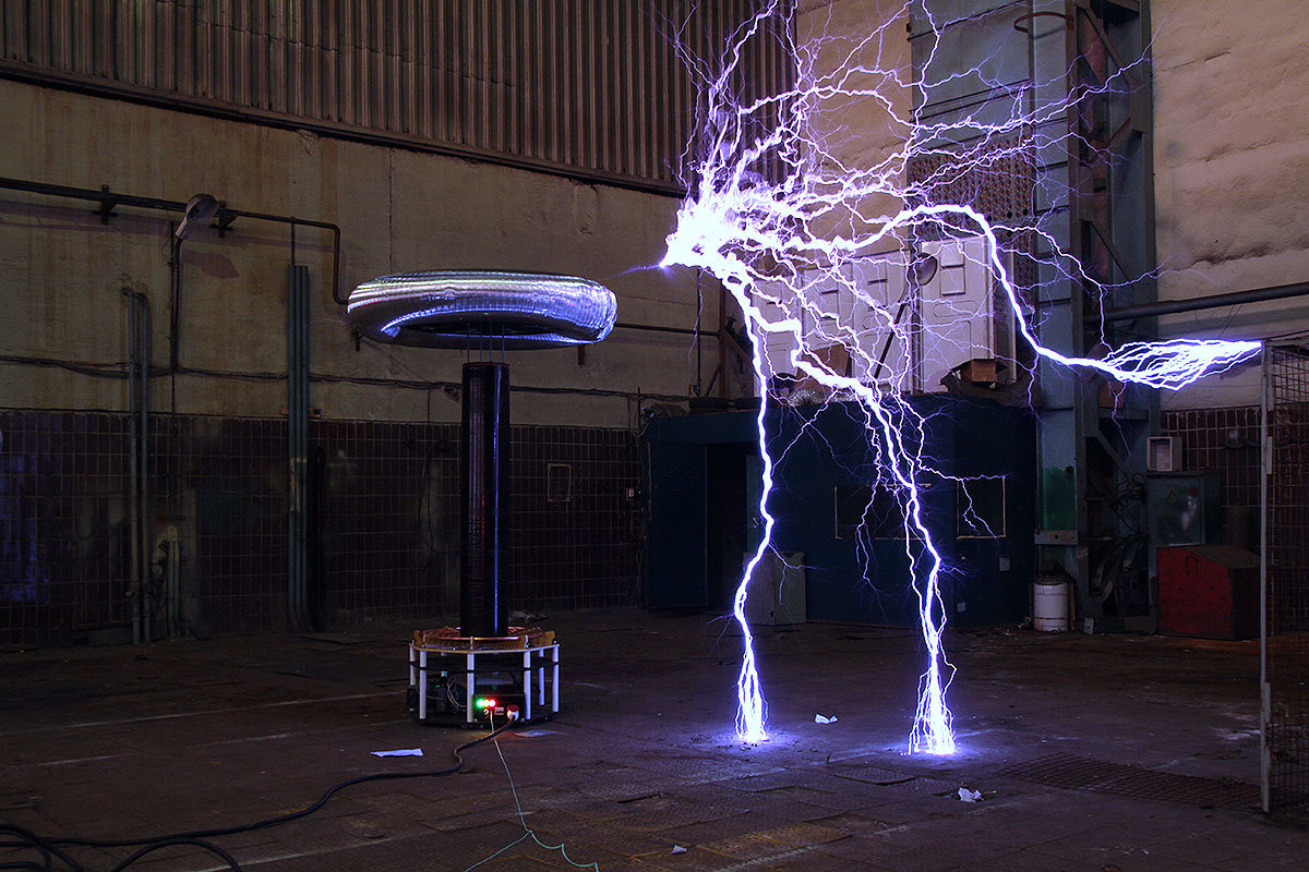
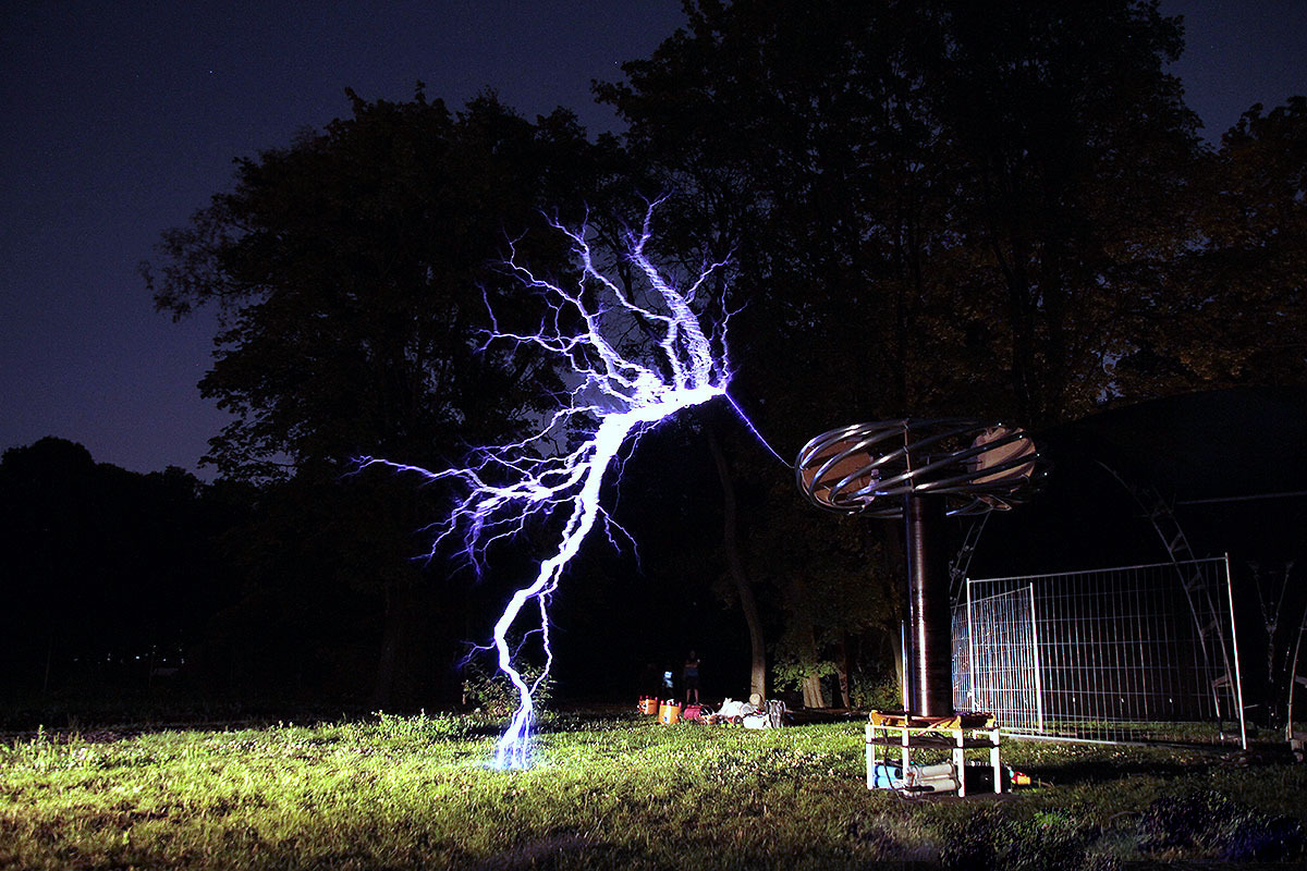
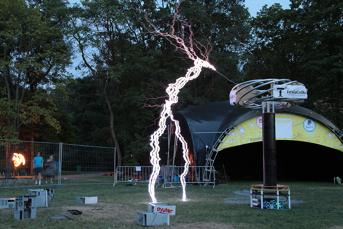
- Maximum recorded discharge length: 6 meters
The technology, of course, was chosen exactly DRSSTC, because with the right approach and no errors, its cost (as well as mass dimensions) turns out to be significantly lower than other options (spark gap or radio lamp) with the same final parameters. Well, and, of course, you can play music on it.
Modular principle
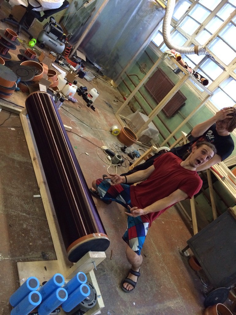
During the initial design of a sufficiently large Tesla coil, the project can be divided into several modules (primary winding, secondary winding, toroid, case, power inverter, driver, control panel, auxiliary electrician, etc.), each of which is thought out and manufactured separately, after which they come together, are consistently tuned and debugged in the process, and as a result, they start to emit lightning. Usually, most Tesla transformers are assembled by enthusiasts alone from start to finish, but we, first of all, already had a more or less well-coordinated team with distribution of functions (project manager, designer, developer (he's a tester), and a few people on the pickup - The installer, locksmith, and so on), and, secondly, the task itself was quite ambitious, and wanted to do it at no extra cost, but at the same time more or less qualitatively, as far as possible for the prototype and unique design. Therefore, everyone could go about their business, simultaneously communicating to synchronize the modules with each other, and I, being this very project manager, can tell about each of the modules separately, and also show what happened as a result.
Preparation and material processing
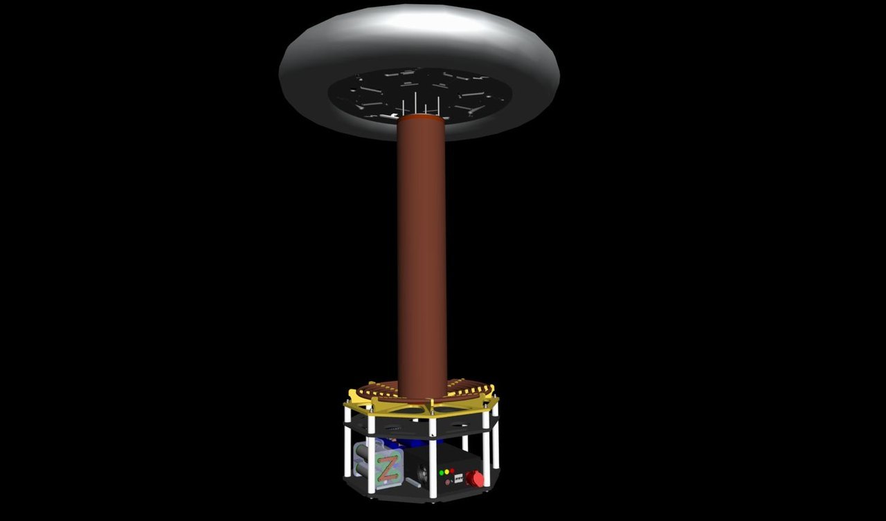
After discussion, understanding and various verbiage on the topic, the overall concept was approved by a collective decision and I depicted a primitive sketch in 3ds max. A sketch was needed to realize the scale of the task, to understand the basic mutual proportions of the modules, as a starting point for the design and to raise the morale of the team. Based on the sketch, the designer assembled the project in Creo Elements (then Pro / Engineer), already in compliance with specific dimensions, ways of connecting the parts between themselves and other nuances. According to the results of this project, the following drawings were created: parts of the case, base of the primary winding, toroid, boxes for automation and electrics, as well as a block of primary circuit capacitors ( MMC ).
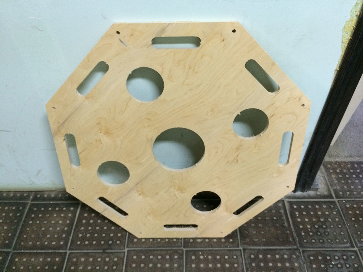
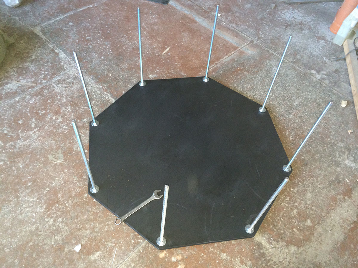

As construction materials, we used glass fiber 18 mm thick, processed by water-jet cutting (due to its high structural and thermal stability, other processing methods were unprofitable), thick plywood for the body and aluminum-plastic composite for the automation unit (for shielding from the powerful front of electromagnetic interference, adversely affecting its own control circuit), as well as polycarbonate in some places. Plywood and plastic were machined on a CNC milling cutter owned by a factory neighbor, where our team dealt with all this indecency. Creo Elements allows you to create immediately ready control programs for CNC, which greatly helped in the process - we simply, in fact, rented a machine and did what we needed on it when necessary.
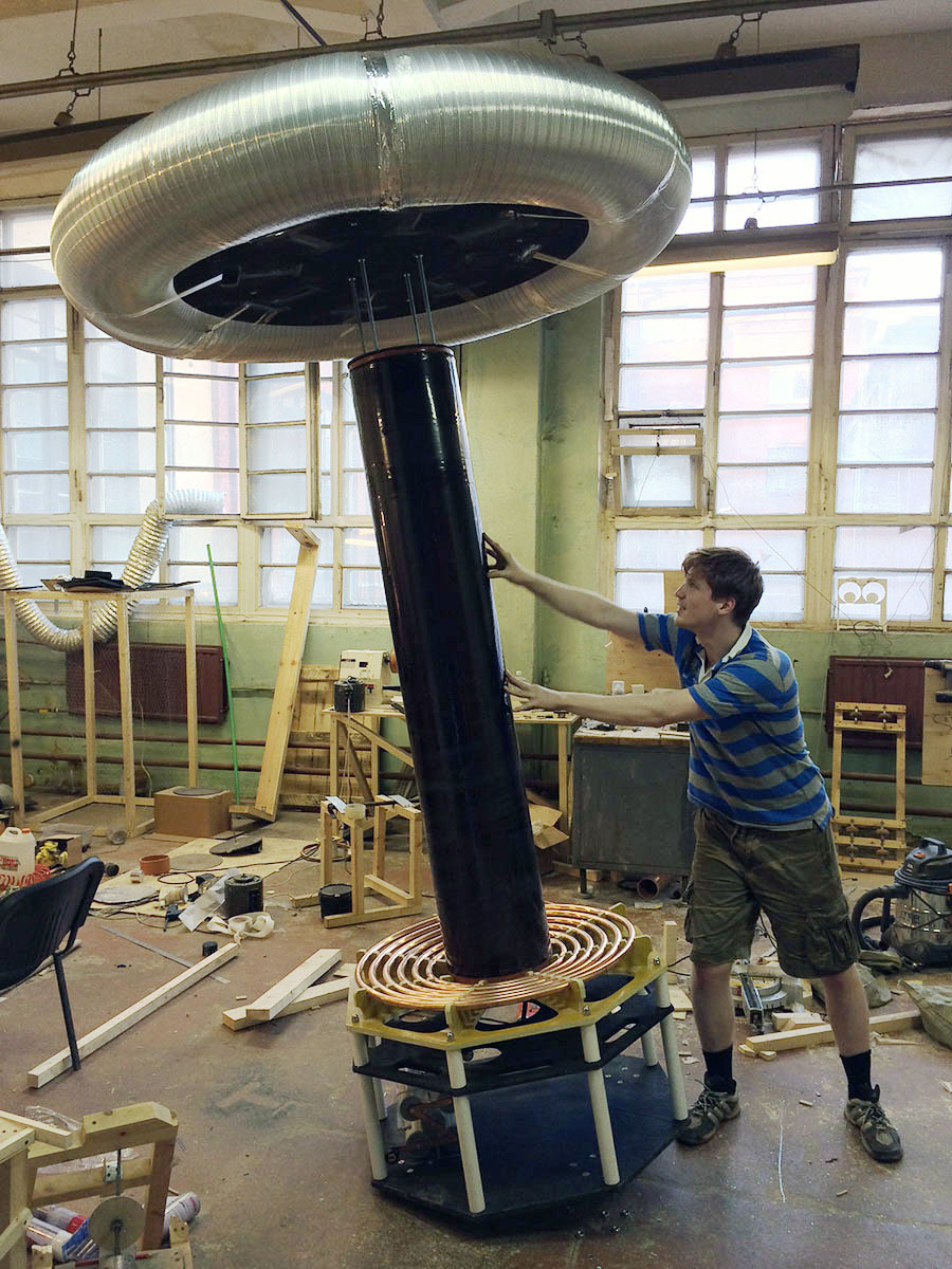
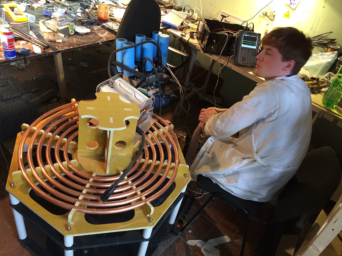
Primary and Secondary
The secondary winding was wound on a classic frame - a large orange sewer pipe made of PVC (seriously, this is the best option available for Tesla coils of any dimensions in terms of price, availability and compliance with the task). The coiled to coil enameled wire (diameter 1.06 mm) in a single layer, then coated with epoxy, turned the pipe into a huge inductor, looking forward to its minute of glory - the secondary of the giant Tesla coil. The final dimensions of the pipe turned out 310x1800 mm.


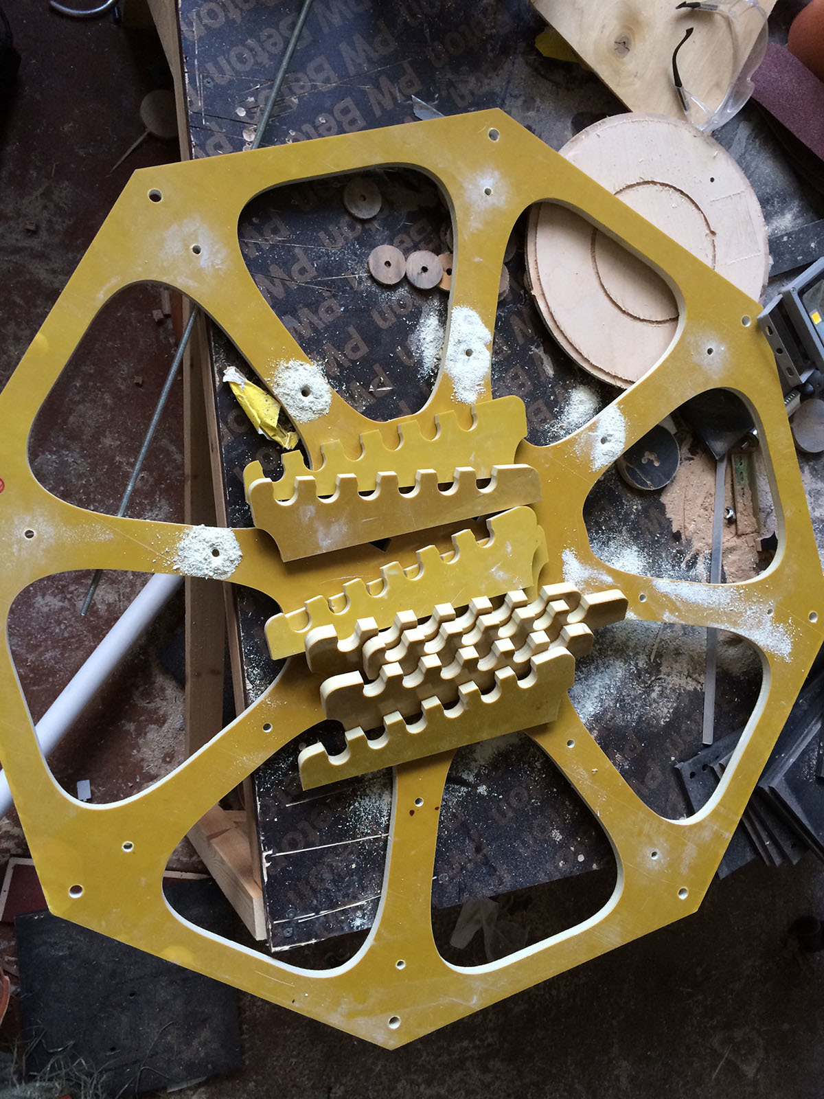
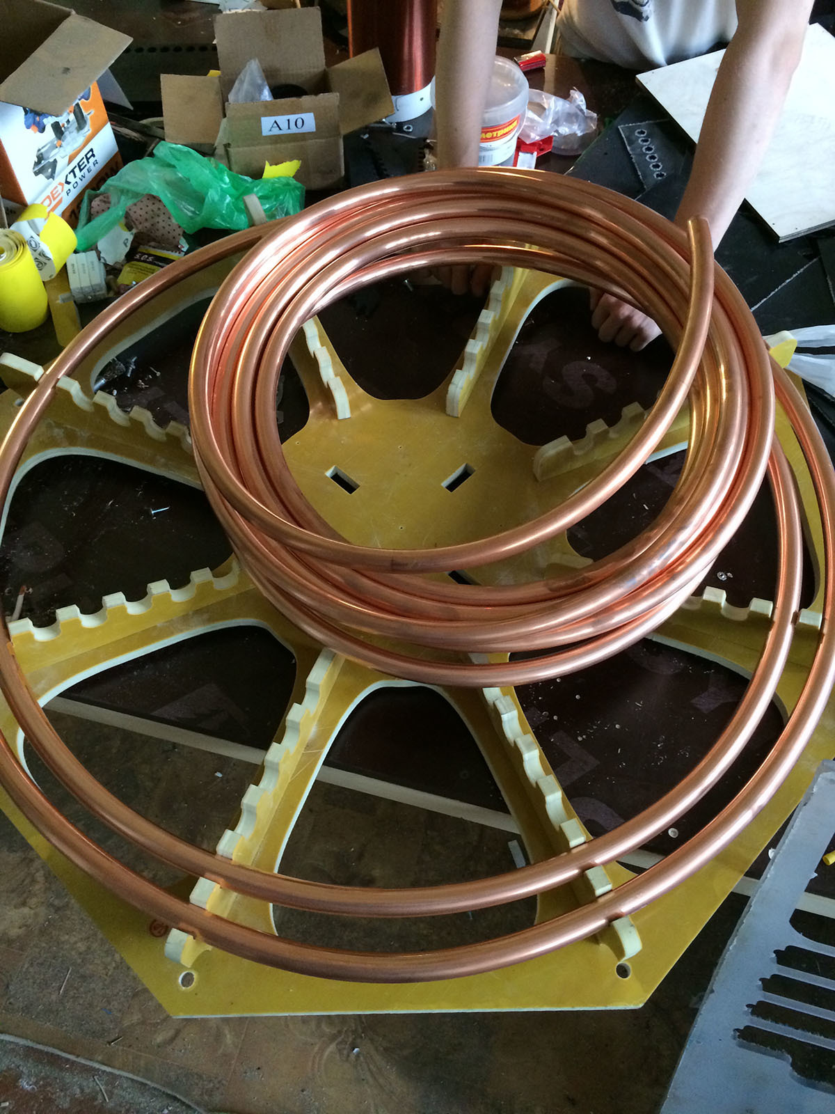
The primary winding is also a classic - we wound a copper tube for air conditioners with a diameter of 22 mm (7/8 inch). The coils gently went into grooves cut into glass fiber plastic with a jet of water with an abrasive under pressure of thousands of atmospheres, and now two modules, the primary cell and the secondary - the skeleton of any Tesla coil - connected to each other. The project gradually gained shape and color.

Toroid
With a toroid, an essential element of any powerful Tesla coil, however, everything turned out to be more complicated. Initially it was also intended to follow the proven road and use aluminum corrugation for ventilation. In practice, however, it turned out that this is an extremely one-time solution - the corrugation is instantly wrinkled from any careless movements, and with the planned dimensions it will have to be replaced each time the device is transported.

Therefore, after some research into the issue, I

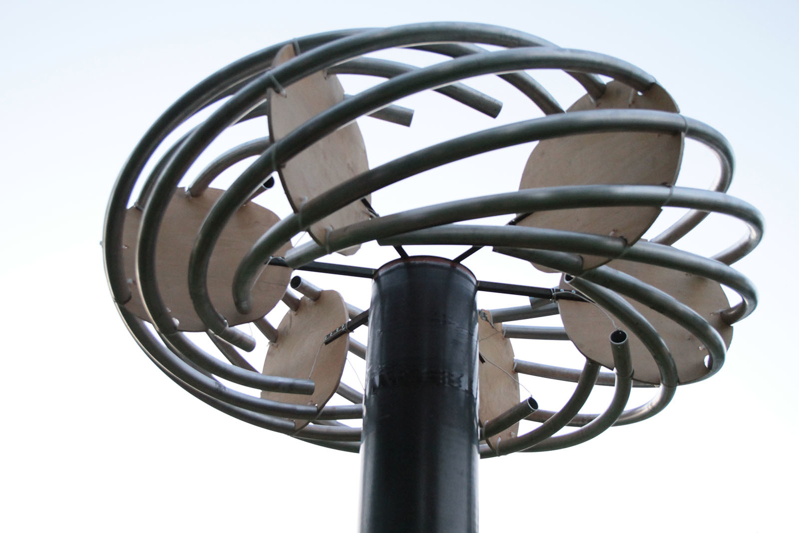
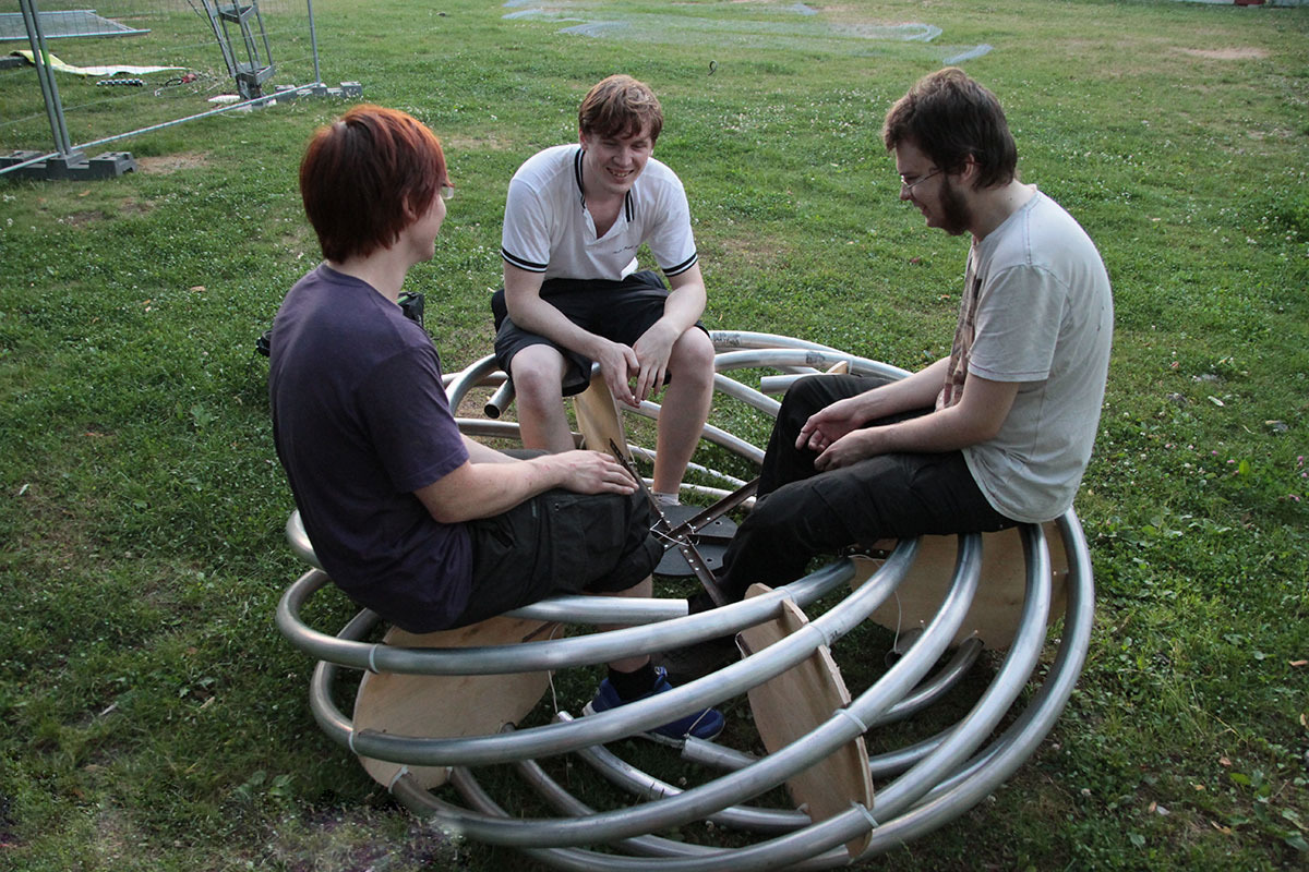
In general, the result turned out to be very unusual in appearance, relatively simple to manufacture, reliable in operation, and surprisingly effective in comparison with other known versions of this important part of the Tesla coil. The diameter of the aluminum pipe is 50 mm, and the overall size of the whole piece, resembling a UFO, is about two meters in diameter. Circles-spacers for the tubes were cut out of plywood all on the same CNC milling machine, and I welded the central frame from a steel corner.
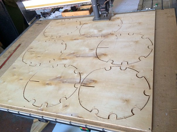

On this, in principle, the structural part was completed.
Power unit
In the power inverter for large Tesla coils, IGBT-modules are often used - sort of black (or white) bricks with two-three (sometimes up to 10) power terminals and several terminals for control, which are regularly used in power inverters - powerful charging units, transformer substations, frequency converters for motors, electric transport, etc. Due to the large size of the crystal, these modules are able to withstand significant short-term overload on the operating current (up to 10 times the nominal), which is extremely ygodno pulsed inverter Tesla coil according DRSSTC-technology, since the duty cycle (the time during which the vibrations occur in the circuit and current flows through the transistors, warming of crystals), there is typically about 5-10%. But, on the other hand, the absolute majority of these IGBT modules are designed for operating frequencies of the order of units, less often tens of kilohertz (however, the situation has improved recently and modern modules can operate up to 100 kHz). Using them at a higher frequency often leads to problems with the control of valves, overheating and explosions (wherever without explosions).
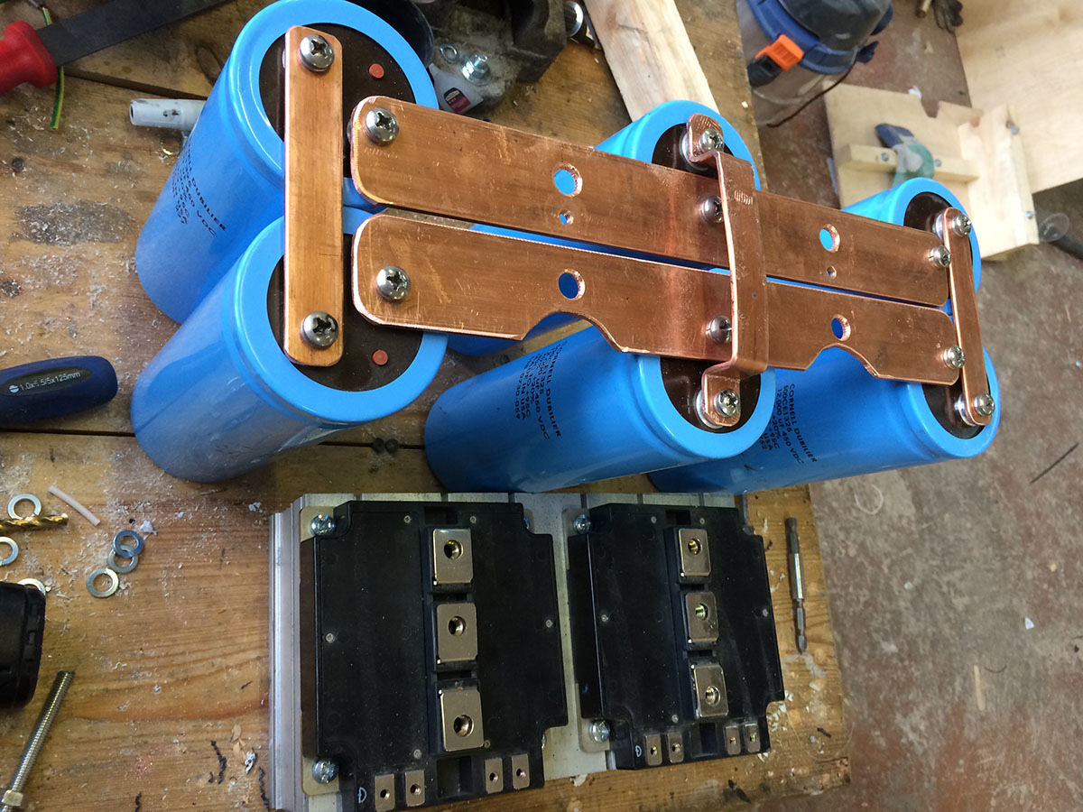
The cost of one module, even used, can be relatively high (from units to hundreds of thousands of rubles), so we decided to play it safe and supply two CM600DU-24NFH modules with a pulse current margin (600 amps of continuous current, 1200 volts, two transistors in the half-bridge inclusion) according to the “full bridge” scheme (as is known, the full bridge is made of two half-bridges - K. O.), or simply “bridge”. Planted on the radiator corresponding to their size after a couple of teaspoons of thermal paste KPT-8, they were connected by copper tires and equipped with the necessary body kit - power electrolytic and film capacitors.
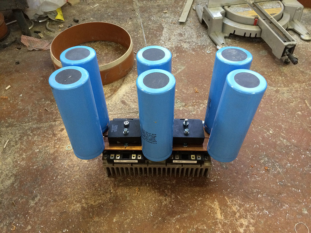
In inventing the actual way of connecting these parts together there is a lot of cunning empirical know-how designed to reduce risks and maximize the reliability of such structures, but the fields of this record are too narrow for me to tell about them if you understand what I mean. There were no guarantees that the resulting piece would not explode at the first attempt to turn it on, but at that time it seemed an acceptable risk.

Automation and electrics
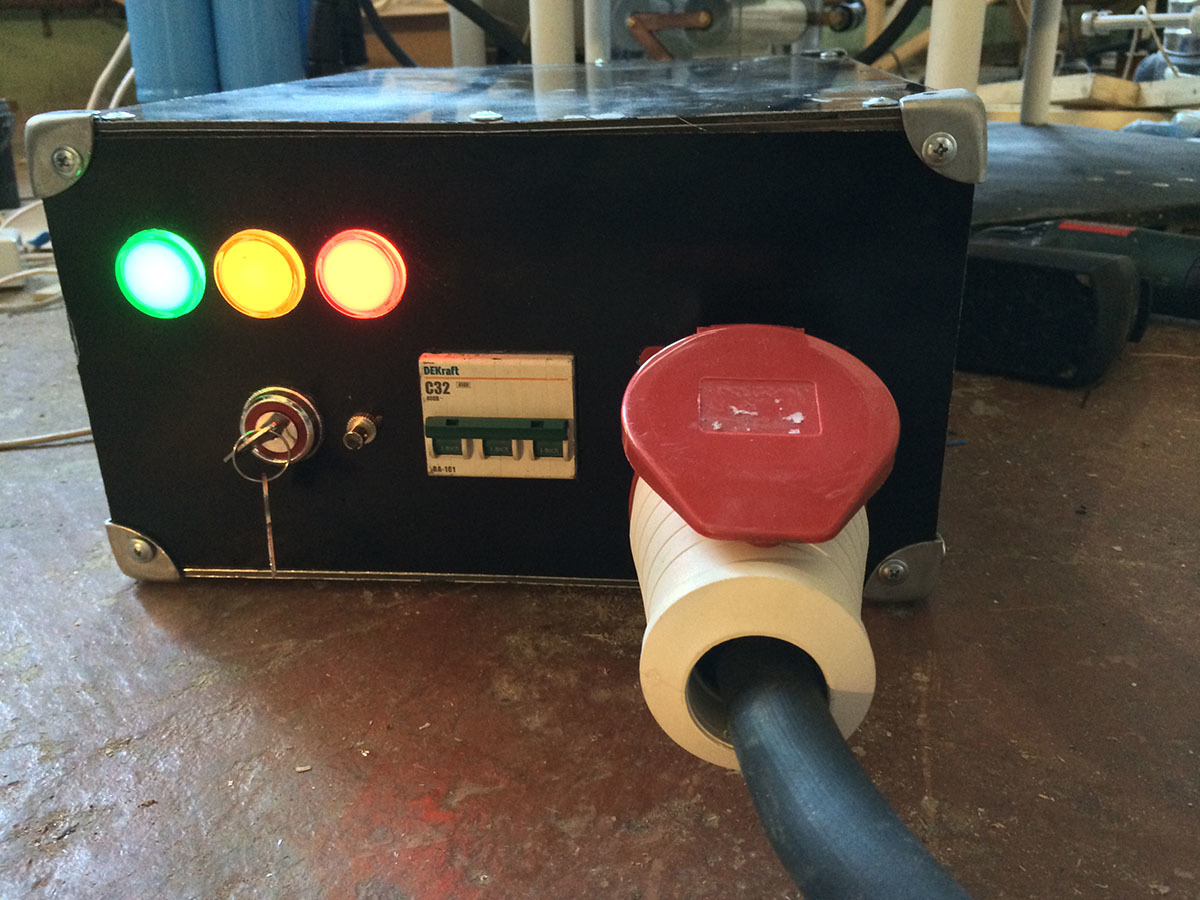
The manager of the electrician did not contain anything particularly interesting. It was necessary to ensure a smooth charging of electrolytes (so that they would not knock out the automatons in the panel when the unit was turned on) - the automatic starter (in fact, a large power relay) and several power resistors coped with this.

A 150 amp diode bridge straightened the network (by the way, the whole structure was created, of course, for three-phase power supply, with which there were a lot of different interesting discoveries - before we did not do anything for three phases, especially such power), fans blew a diode bridge and at the same time, the radiator of the power unit, and the light bulbs on the front panel depicted a traffic light, kindly telling you when you can touch parts of the coil with your hands, when it is better not to, and when it is desirable to be at the maximum distance from it so as not to catch the discharge at the top.

Driver
The master driver is a separate topic, and perhaps I will sometime be able to tell about it in more detail. Its main purpose is to supply the required signal to the gates of transistors, turning them on and off in such a way as to maintain and amplify the oscillations occurring in the primary circuit, while modulating them with the frequency supplied to it from the control panel melodies on Tesla coils). Well, there is also a mass of various functions that optimize this process and handle all exceptions (such as exceeding the maximum allowed current for transistors - OCD , protection against overheating, and so on), a phase detector, so-called. the predictor that switches the transistors at zero current, and other things that are absolutely necessary for the operation of the Tesla coil inverter. Its current circuitry (as well as the layout of the board, photographs of the board, information about the components used and the fact of the existence of this board) is the intellectual property of the developer, and therefore I cannot share it, but even if I could, I’m afraid I don’t have enough understanding and professionalism to clearly tell about it. Tesla's coil is very easy to describe using analogies on the fingers, but the mathematical model, which is correct from the point of view of electronics development, is extremely complex and contains a lot of unobtrusive subtleties (as well as with the power unit), so most tesastrobuilders simply use a set of rules of thumb and ready-made solutions the construction of its coils, which in our case was not applicable. The network has a lot of articles about the principles of the operation of the DRSSTC, as well as open (and closed, but available for purchase) driver projects, for example, from the Chinese counterpart Loneoceans - anyone can read more there.
MIDI remote
The control panel (also known as interrapter) was a simple MIDI synthesizer with several primitive settings that received MIDI files (or data from knob-twists) at the input and output a control signal to the driver via an optical cable. With him, in principle, everything was simple and understandable, because we decided not to waste time on developing what you can buy, and just did it - bought it ready. He, of course, turned out to be a buggy semi-finished product, but he saved hundreds of man-hours for studying the midi-protocol, making a motherboard, debugging a microcontroller, and catching inevitable bugs. The main thing is that he coped well with his task at that time. The console was purchased from an American colleague, a mec-speaker, and at that time it was the only commercially available remote control with an SD card, that is, capable of playing music without an external MIDI device or laptop. This was critical, as there were legitimate fears that interference from the work of such a large coil would firmly hang all the electronics in a certain radius from it, and the hanging of some kind of midi keyboard, the developers of which in a nightmare could not foresee a similar level of spurious signals, if this is the keyboard controls the Tesla coil, which interferes with it, is fraught with uncontrollable positive feedback and, as a result ... well, explosions. We did not want explosions.

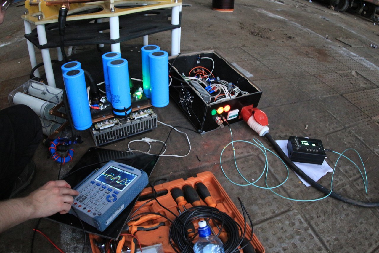
Since the console was sold as a wired and stitched board with a scattering of remote parts, we had to develop a case for it, where the board itself, power, four encoders, four buttons, a display and numerous connectors (four optoelectric transmitters, MIDI input, USB input, slot for SD card). Along the way, the author discovered a lot of various defects of the author, in particular, the absence of any power control (powered by Krona? Lithium-ion? Not heard) that had to be corrected and finished so that it could be used for its intended purpose. The resulting chimera, despite a number of disgusting glitches under some unsuccessful conditions, successfully copes with the main task to this day.I somehow didn’t find his photo, but it can be seen on one of the frames below, in the “initial check” paragraph - the black box next to the power cable in the right part of the image. There is still a frame from the video from the author of the scheme and firmware - here it is.

Condenser battery
As a resonant capacitor, we chose power film capacitors from one of the domestic manufacturers, which were specially developed (according to the manufacturer's catalog) for pulsed operation. Five pieces with a total capacity of about 1.2 microfarads, and a maximum voltage of 20 kilovolts, connected by a copper bus with brass screws. Brass fasteners, by the way, the whole project took a significant amount - due to the huge currents in kiloampers, combined with a powerful magnetic field from the primary winding, and steel galvanized and stainless fasteners are instantly heated red hot, which can eventually lead to unplanned special effects (yes - yes, explosions). Therefore, it was necessary to use only copper and brass in the busbars of capacitors, and in general in all power connections in the primary circuit.The very first tests showed the naivety of attempts to put something ferromagnetic there and / or not sufficiently transmissive of electric current.

The next step was setting up the driver. To do this, it is enough to assemble the primary circuit (capacitor battery, primary and bridge) into one whole, connect the driver to the bridge transistors and smoothly start applying voltage, tracking the waveforms in different parts of the circuit on the oscilloscope. If everything is done correctly, then auto-generation occurs at the calculated frequency (in our case, around 50 kHz) in the primary circuit. There is no need for a secondary one, and there are no digits, but the data collected is enough to set up a predictor, OCD and notice errors in the assembly or selected parameters of the parts. This part turned out to be simple and easy (by the way, in this mode, the primary winding may well work as an induction cooker for cooking - there are precedents for cooking scrambled eggs in a frying pan on top of the primary device)and we went along with the almost born child into one large and semi-abandoned factory workshop, to finally verify our creation in vivo.
The test turned out to be fast, bright and a bit predictable: after giving out a few four-meter discharges, the Tesla coil said “you are tired of me, I'm leaving” and stopped working with a loud bang somewhere inside the case. A subsequent study of this phenomenon showed that in the process of selecting the optimal frequency, we made a mistake on one turn of the primary winding, and the mismatch that occurred when switching transistors was enough for them, as they say in professional melodies, to abuse them. silicon contained in them in a gaseous state (as in the joke that transistors work, they say, on magical smoke - when it goes out, they stop working). A spare set of transistors remained in the lab,and the remainder of the allotted time, we sluggishly quarreled with each other and launched other Tesla coils taken with us as part of a rehearsal for the GEEK PICNIC festival (under which the release of the project was timed).
?
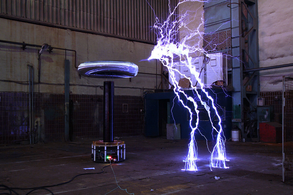
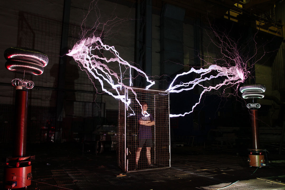
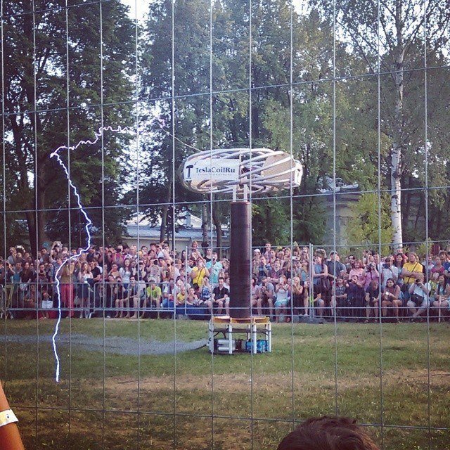
Well, after that there was a bit of work on the bugs, hectic gatherings, arrival on Elagin Island, where the mentioned GEEK PICNIC traditionally takes place in St. Petersburg, night tests before the day of the festival of our coil, already with a new tubular toroid and to the fullest (sorry for intentional tautology). The next day was one o'clock X (during which about fifteen minutes we jumped all around the unwilling masterpiece until we found a joint school - the current transformer was connected in the wrong phase), Vivaldi, Imperial march and Mario on lightning, removing it all quadcopters with cameras, half a thousand viewers who stared at what was happening, who admired, who were surprised, who were indifferent, who, through the screens of their smartphones and tablets, had a few encores in daylight,where the discharge was barely noticeable (but it was audible perfectly) and - already after the end of the festival, but before the park closed - a few minutes of operation of the largest Tesla music coil in Russia in the summer twilight, which still sometimes appear before my eyes.


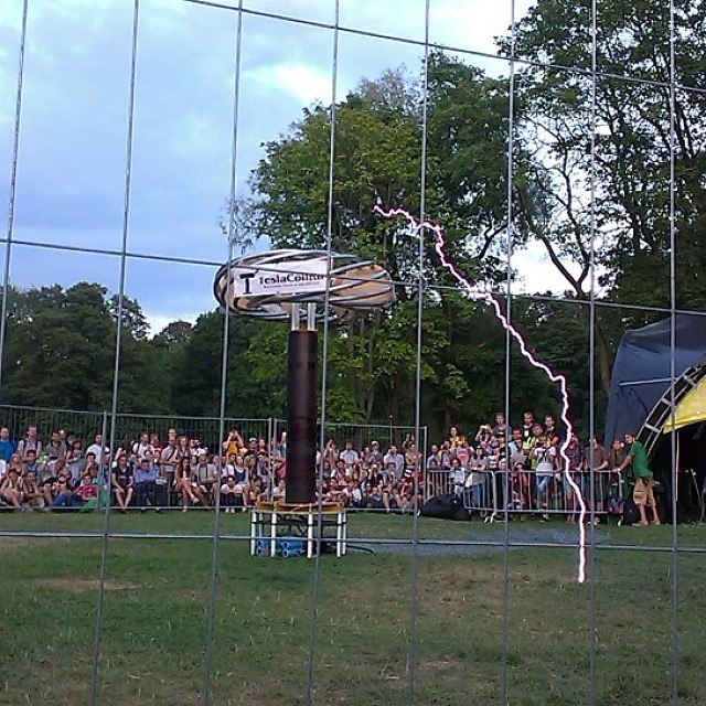
Holding a remote control from such a thing and looking at almost real six-meter lightning, threatening tentacles cutting air, arising and changing with the movement of your fingers - this is still one of my strongest memories of nine years of work on Tesla coils and special effects of high voltages. But, alas, nothing lasts forever, and outraged by what is happening (they say, people don’t want to leave while you are having fun), the park guard demanded that the shop be turned off and rolled out, which I had to do.

, . , , , , , , . . - . , , - . Who knows.
:

Newfag disclaimer
. . - , .
Source: https://habr.com/ru/post/401429/
All Articles