The dark side of the MH-Z19
What's again? How much can you?
Yes, today we will again talk about all of us, our favorite Winsen MH-Z19 carbon dioxide sensor. No, there will be no repetitions *.
')
* nearly
As you can see,horror stories about the dangers of high CO2 concentrations in a room regularly appear on the pages of this resource. And although the claims that concentrations above 1000 ppm carry hell and death are slightly exaggerated ( Wikipedia says that at least some effects start at 1%, i.e. 10,000 ppm, while the sensor has a full range of 5000 ppm) - CO2 can serve as an indicator of the presence of other bad things due to insufficient ventilation. Therefore, I also decided to join the fascinating world of CO2-metry and got hold of the above-mentioned sensor.
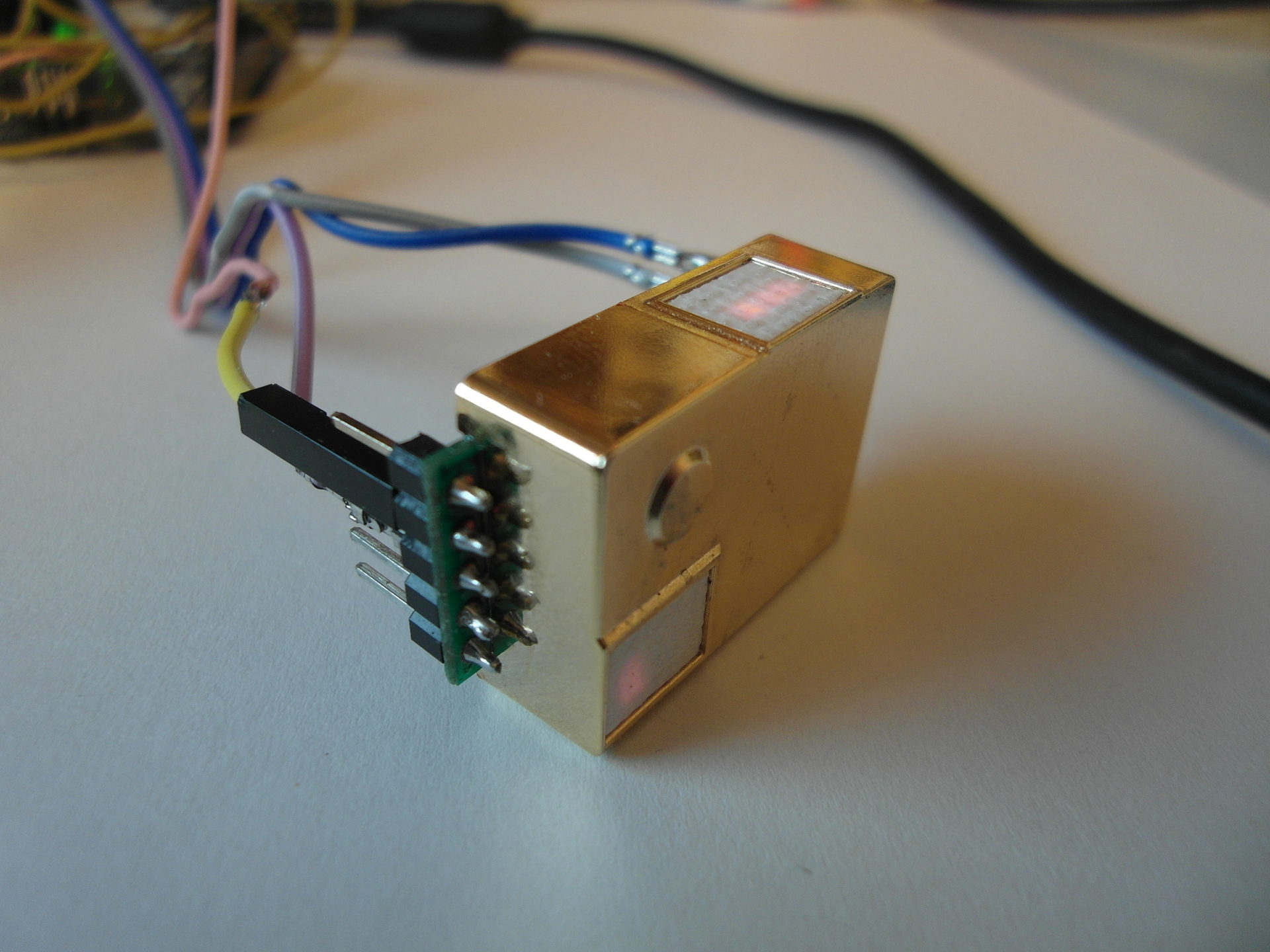
First of all, of course, I connected it to the Arduin. Skopipastil (with the necessary changes) code from the article , the treasured numbers appeared on the small screen.
But while I copy-pasted, a worm of doubt crept into my soul - and why does this sensor produce nine bytes, and only two bytes per CO2 of them? Maybe he wants to tell me something else?
An Internet search brought me to such an interesting page . The author is experimenting with the MH-Z19 and reveals his reaction to undocumented (and documented) commands. He has not tried all the teams yet, so it will remain for our share where to frolic. This is what we will do.
First of all, let's deal with the “classic” team 0x86 (or simply 134), with the help of which we get the CO2 concentration. Revspace reports:
That is, the response of the sensor to this command also contains the temperature T (shifted by 40 degrees) and two quantities of unknown purpose — one-byte S and two-byte U. S takes values of two, and U when the sensor is started drops from 15,000 to just over 10 000
How to understand what the numbers S and U mean? Of course, you need to draw a graph! In any incomprehensible situation, draw a graph.
So, the CO2 schedule:
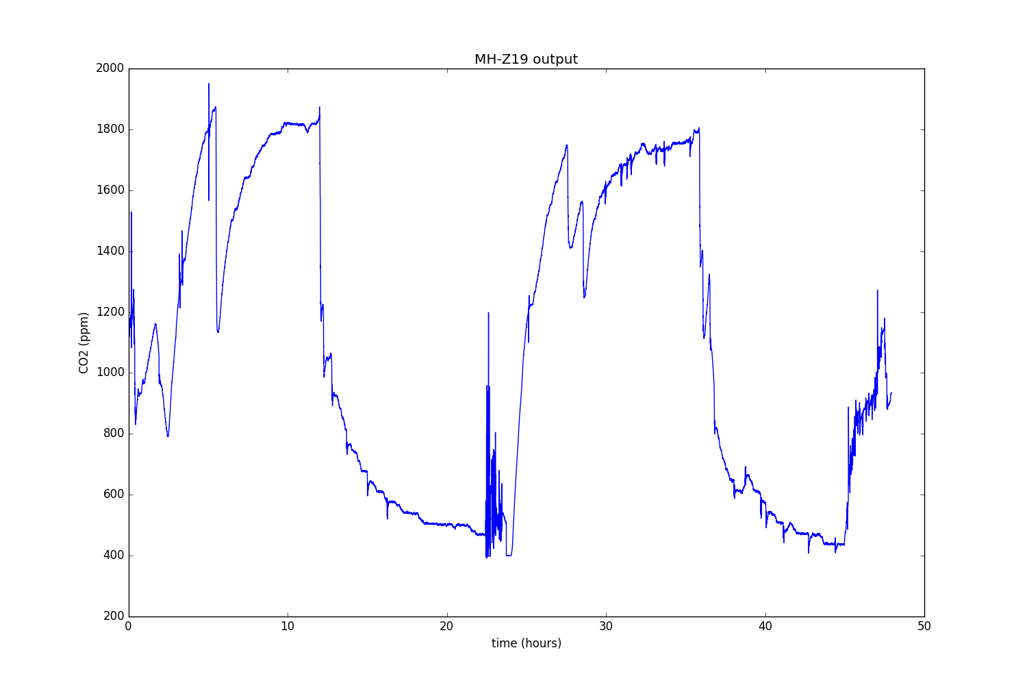
In principle, it seems to be true. Only periodic bursts are grieving. It seems that this is because my sensor is just lying on the table, and at the slightest breeze, his readings go astray.
Temperature:
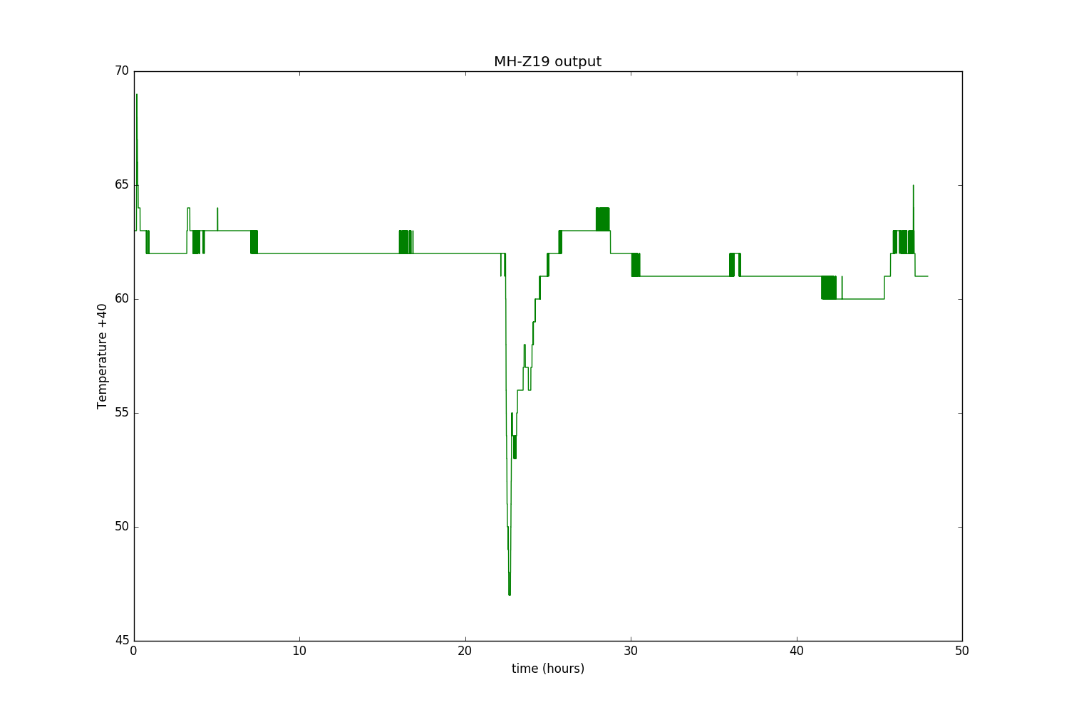
The moment when I opened the window is well noticeable. It moves up to 1 - 2 degrees, which is not bad for an undocumented opportunity. However, if you recall the principle of the NDIR sensor, you can understand that you should not expect great precision from the thermometer built into it. These devices measure the absorption of light in the far-infrared range, and to generate this light, the old kind Illich lamp is used, and you can even see through the windows how it lights up every five seconds (just such a moment is caught on QDPV). And this light bulb consumes a lot of energy and, as a result, heats the entire sensor, and how much it heats it depends on the short-term conjuncture of the air flow.
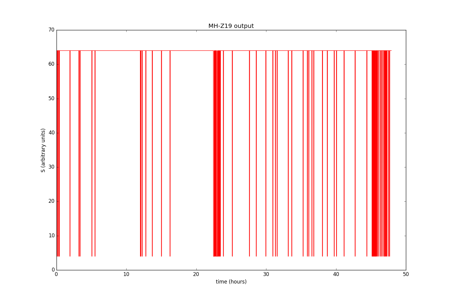
We approach the most interesting. S value:
Does not say anything? Me too. With grief, we will draw CO2 and S on the same graph and increase it slightly:
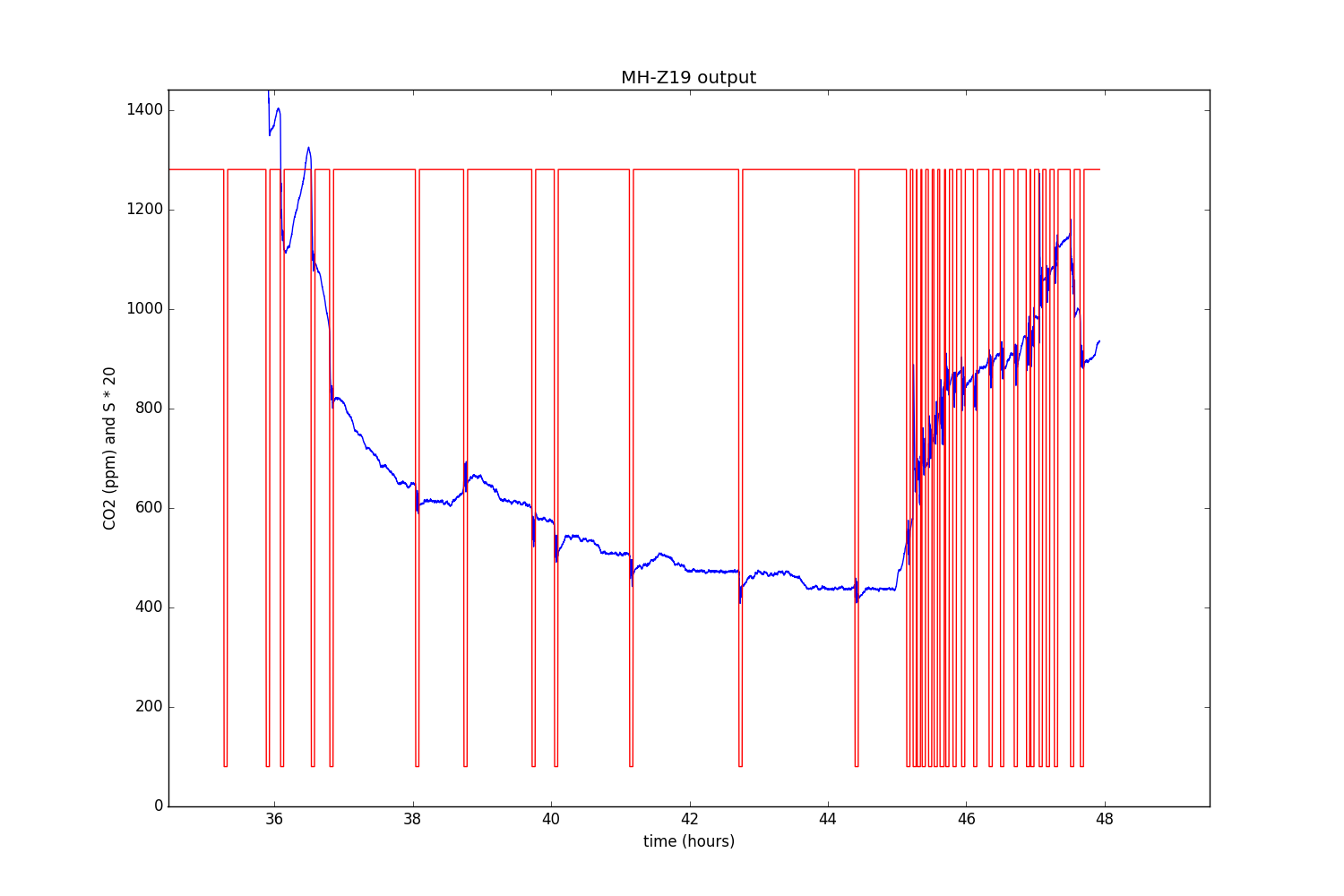
Aha Now everything is clear! When everything is good, S is 64, and when the CO2 sensor starts to sausage, it drops to 4. Thus, you can use S to find out how well the sensor feels and how accurate its readings are.
Left, as they say parachutists, the extreme value - U:
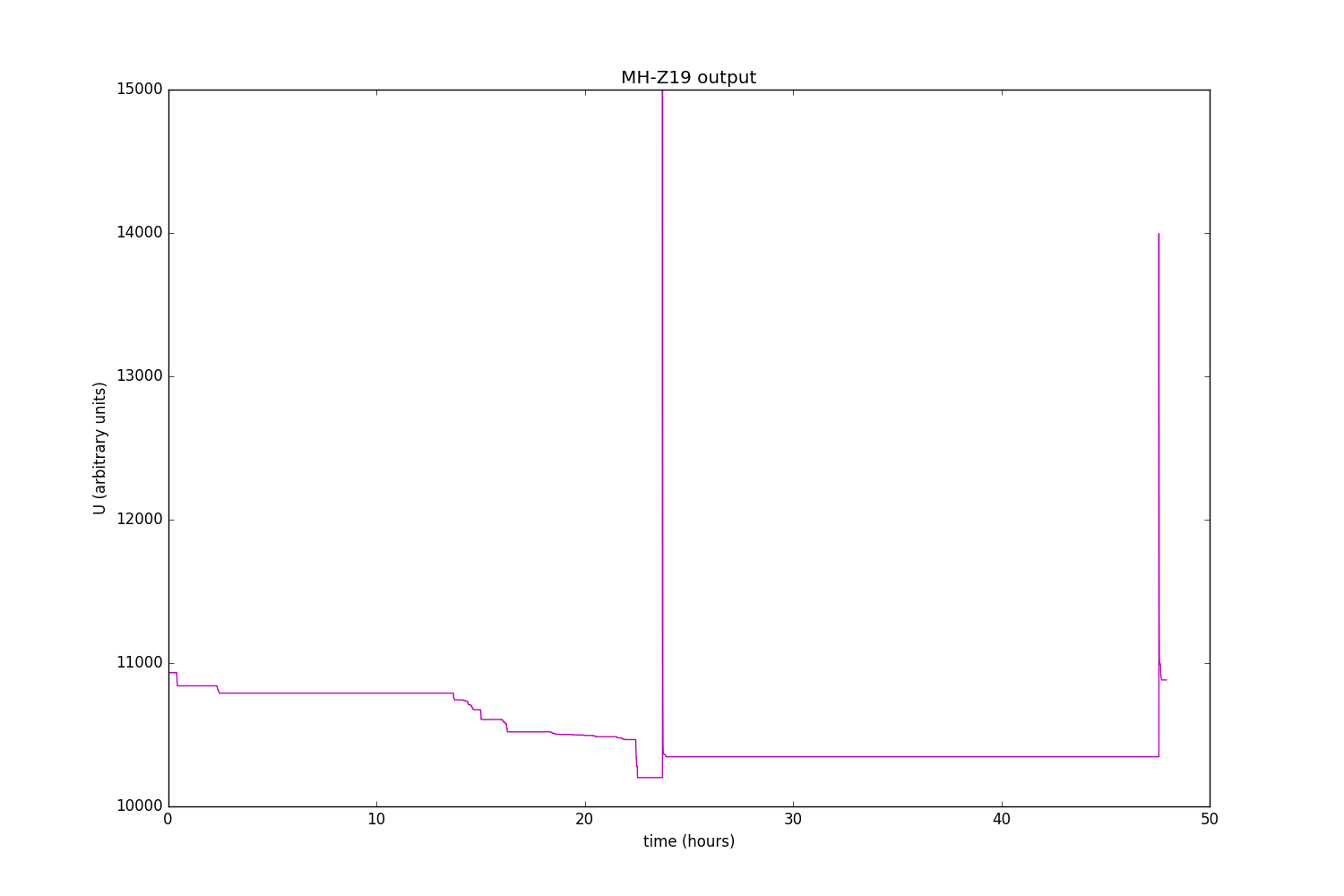
Unfortunately, the focus with the imposition here does little. It can only be seen that, as promised by the revspace, at the beginning it is equal to 15,000, and then falls to just over 10,000 (but it may fall a little after a long time). And once a day the cycle repeats.
But when I connected the sensor power supply not to 5, but to 3.3 volts of Arduin, the situation changed:
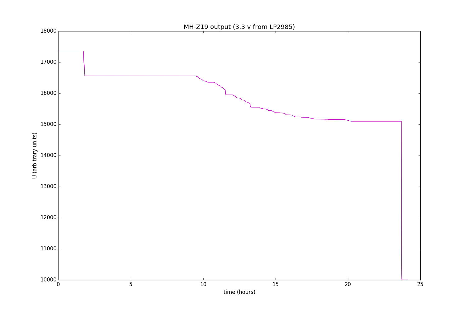
3.3 volts on arduin is taken from the LP2985 chip, which is a 160 milliamp linear stabilizer. And the bulb, judging by the articles on the Internet, eats about that much. When looking at the sensor, it is noticeable that the light bulb with this power supply flares up for a longer time than with five volts. And the value of U is one and a half times higher.
The following hypothesis emerges: the sensor automatically determines how long it takes to light a light bulb in order to get enough infrared radiation, and if there is not enough current, it burns the light bulb longer. And the value of U just reflects the time of the light bulb burning (or some other related value, for example, the energy expended).
To test this assumption, we power the sensor from a lithium-ion battery, which certainly can deliver much more current:
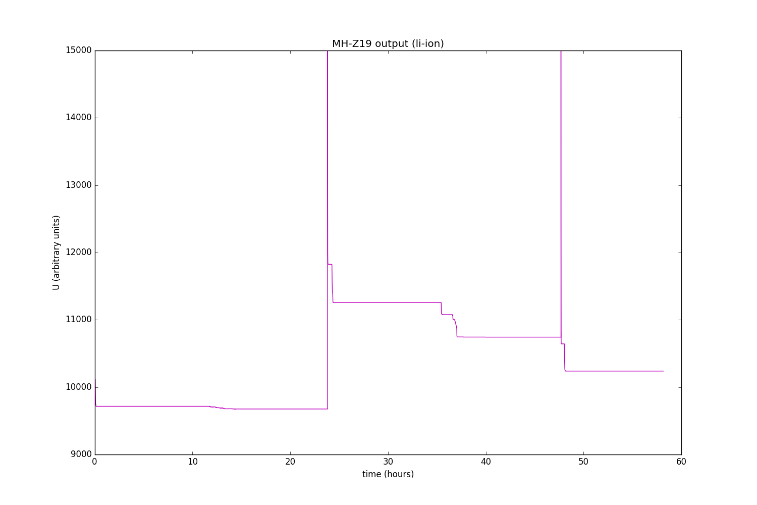
And indeed, U sometimes falls below 10,000! However, this is obviously not absolute proof, and after 24 hours everything becomes almost the opposite. So the hypothesis remains only a hypothesis, but I did not invent anything better.
UPD: Dear unsvp did solve the riddle of the U value. I give him the word:
Add nothing, except that the schedule:

Why I did not think of it myself? It's simple. I drew a graph of four quantities at once and calmed down on this. And it was necessary to draw two values (as in the picture above), then the extraneous garbage in the face of S would not interfere with perception. Do not repeat my mistakes.
Perhaps add this: see a step of more than 1000 ppm at 48 hours? This sensor is so automatically calibrated. At the same time, the value of U has fallen compared to what it was before calibration. While it is obvious that the actual concentration of CO2 in this period only grew. The conclusion from this is very simple - the value of U is not quite the “raw” value of absorption, and is already calculated after adjusting for the current calibration, apparently representing a certain difference between the minimum readings in the current and previous calibration cycles.
In general, in my opinion, auto calibration (at least in the form in which it is implemented in MH-Z19) is evil. Revspace says that it can be disabled with the command 0x79: ABC logic on / off.
/ DFC
Well, with one team figured out. It's time to go on, but the article is nearing its end, and another 255 teams have not been tested!
In an article on revspace, the list of tested commands ends with:
In addition, commands with smaller numbers are not all checked. Thus, a little more than half of the total number of unexplored commands remains.
Without further ado, I decided to give commands randomly (more precisely, pseudo-randomly). And that's what I got:
Here, the Command is what was sent to the sensor (the command number itself is the third number from the beginning), Response is what the sensor answered, you can not watch the rest (CRC is the calculated / actual checksum, CO2 / t / s / u is the result of the breakdown sensor response to four numbers, as if he responded to the "default" command).
As you can see, not a lot. Moreover, from some point on, the sensor refused to give out anything but zeros. The last thing I got from the sensor was:
And then zeros. I tried to enter commands sequentially, starting from 0x8e - again zeros. I tried to give the "standard" command 0x86 - zeros. Did I kill the sensor? In truth, all the conditions for this are present - I do not enter the undocumented commands, so I also connect the sensor interface directly to the five-volt arduine, although the datasheet directly says that it is designed for 3.3 volts.
First of all, I tried the good old recipe of any enikeyschik - turn it off and on again. I mean, I took it out and stuck it at the sensor plus the power supply while everything else was running. The sensor gave approximately the same as in the last quoted passage (but with slightly different numbers). Yeah, it means that the sensor is not quite dead and every time it says something, the Stirlitz guessed.
Then I thought about it a little more and figured it out before one truth - those zeros that we saw above are not the answer of the sensor at all. In fact, the sensor is silent, and my program draws what the arduin function of receiving n bytes has issued (that is, zeros). And if every time before accepting to make sure that there is something to receive, it turns out that there is nothing to accept. Is that except when the sensor has just rebooted.
It turns out that the sensor completely stopped perceiving any commands. Apparently, 5 volts on the serial interface were not in vain. Yes, the article did not work out somehow. Thank you all for your attention. We disagree, there is nothing to look at.
Oh, wait ...
See those numbers at the end?
Nothing like?
Of course, this is the good old line feed ! In other words, 0x0D 0x0A - so it is customary to translate a string, for example, in Windows (and in Unix it is easier to do it - 0x0A, because some files open lines in a notebook with a notepad).
So maybe the sensor wants to tell us something in human language? However, if this language is Chinese, it will not help me much. So let's hope that this is a more understandable language, and decipher the message according to the ASCII table:
Got as many as six letters. But that same sensor said when loading a little earlier:
The difference is obvious - the KB200 line has changed to the MODBUS line. The rest seems to be not a text at all, not even Chinese characters - if only because most of them change from time to time.
So what does the sensor tell us? On request, the KB200 search on the Internet produces a keyboard, core receiver, iron, changing table, PTZ camera control controller, a mixer, unless the hell does not produce a bald one. It is good, but it is not quite clear how to apply this knowledge to our case. Well, let's look for MODBUS. This time, Wikipedia itself is at our service:
The hypothesis suggests itself: after one of the undocumented commands, the sensor has switched to the Modbus protocol and now with available methods it notifies us about it. Since there are no other options foreseen, we will deal with direct verification of this hypothesis, that is, we will try to contact the sensor via Modbus.
On the Internet, a Modbus implementation for the Arduin was found. But that's bad luck - Arduino Leonardo is not supported, and I have, by horrible accident, Leonardo.
But, as I soon realized, this is even for the better. Modbus protocol is as simple as a penny. And besides, it painfully resembles the “native” protocol MH-Z19. So why drag all the nastiness out of the Internet and painfully understand it when you can in two minutes (well, two hours) realize everything you need yourself?
So, earlier we, wanting to find out the readings, asked the sensor to issue them as follows:
Or in decimal terms:
Where 255 is the magic number, 1 is the address of the sensor, 134 is the command, 121 is the checksum byte.
And what will it look like in Modbus? There will be no exact match, but you can do this, for example:
1 - sensor address.
4 - team number. Commands in Modbus can be counted on the fingers, and so far we will be interested in only two of them - 3 and 4. For reasons hidden in the darkness of ages, they are called Read Multiple Holding Registers and Read Input Registers, and in fact give the command to read the specified the number of two-byte numbers at a given address. Command 3 reads numbers available for reading / writing, and command 4 reads only.
0, 0 - the address at which we are going to read (in this case, 0). If you specify the same address with the command 3 or 4, we will get different results in general.
0, 4 - the number of numbers that we want to read (in this case, 4). There is a funny moment. Although you can set this number up to 65535, in fact, the protocol allows you to read no more than 125 numbers at a time. And all because the response indicates the number of bytes of information sent, and it takes only one byte (and the numbers are two-byte). Also, as I understand it, the length of the response itself is limited to 255 bytes.
213, 197 - two bytes of checksum ( CRC16 ). In general, this is the most difficult moment in all of our implementation. To tell the truth, I didn’t even understand how it’s considered, but simply copied the code from here . Since there is a different CRC16 sea, it is necessary to take a responsible approach to the choice of function. Check whether a particular function is suitable for Modbus, for example, here .
That's all we need to know about Modbus. At least for a start.
Although you have already guessed for a long time that my appeal to the MH-Z19 on Modbus was completed with success, but let's pretend that the intrigue remains. So far, we still do not even know what our sensor address is (although “in the original” it is equal to 1, it’s far from a fact that it is the same in Modbus). So, we need to repeat the command with different addresses (there are only 255 of them) and see which of our sensors will respond:
It seems that the address is 2. I repeat several commands with address 2 - there is no answer. I change the address to 1 - there is an answer! Thus, the address of the sensor is the same as it was - 1.
And why in the above passage got address 2? Here again the code of my code comes out. After sending the command, I check if there are any bytes at the reception. But since I do it right away, the sensor does not have time to send anything, so the response of the sensor is accepted by the program only in the next cycle. Which can be observed in the above log - the first number in the answer is 1, and it just indicates the address of the sensor. I got around this trouble by simply adding a delay of 50 milliseconds before accepting an answer.
Consider the sensor response to our command:
1 - as we found out - the address of the sensor.
132 - command code and error code. If there was no error, this number would be the same as the sent command - that is, 4. But an error occurred, which is indicated by the high bit set to 1, so the number became 4 + 128 = 132. Therefore, by the way, a command in Modbus cannot have a number greater than 127 - for such a command, a successful completion code would be the same as an error code.
2 - error code.Says what kind of error occurred. As says wikipedia, 02 - Address data specified in the request is not available. So, there is no fish at this address and there is nothing to catch. We will try other addresses.
194 193 - CRC16.
Now, finally, it’s time to go through the address space of the sensor in order to understand where the fish is. I did this simply - I sent a command to read one number with a new address every 0.1 seconds. Since the addresses are 65536, this process is completed in approximately two hours. The results in brief are as follows:
Command 1 (Read Coils) - with any address error 2.
Command 2 (Read Discrete Inputs) - with any address error 2.
Command 4 (Read Input Registers) - with any address error 2.
Team 3 (Read Multiple Holding Registers) gives success at addresses from 0 to 289.
Commands to write values (for example, 6) seem to work, but it seems that the recorded value is soon replaced by what it was. But close this question is not investigated.
So, the search circle narrows down - we need numbers on command 3 and addresses from 0 to 289. You can get an idea of the rich inner world of the sensor using these lines:
True, the archive contains numbers only up to the address 255. Here again, 1 3 is the address and command, 128 is the number of bytes transferred, two bytes at the end are CRC, and everything else is the contents of the memory.
From all this magnificence, we are obviously interested in those addresses whose contents change with time. And here the sensor had two news for me - good and bad. Good - there are such addresses. And the bad - there are only two - 261 and 264. Compare with the “past life”, when four numbers were given at once to one team! I already had my lip rolled out - I thought I would get access to all internal variables. Well, two so two.
Time to build graphics again!
Value at 261:

It looks like a CO2 concentration. It can be seen when I tried to breathe on the sensor. True, the minimum value is noticeably lower than the “reference” 400 ppm, so the calibration leaves much to be desired. One way or another, the sensor is declared resurrected.
The value at address 264:
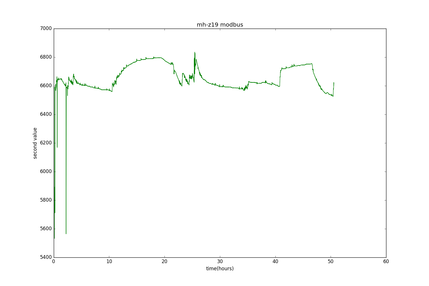
Approximately the same, only on a different scale and inverted.
And both values on the same graph:
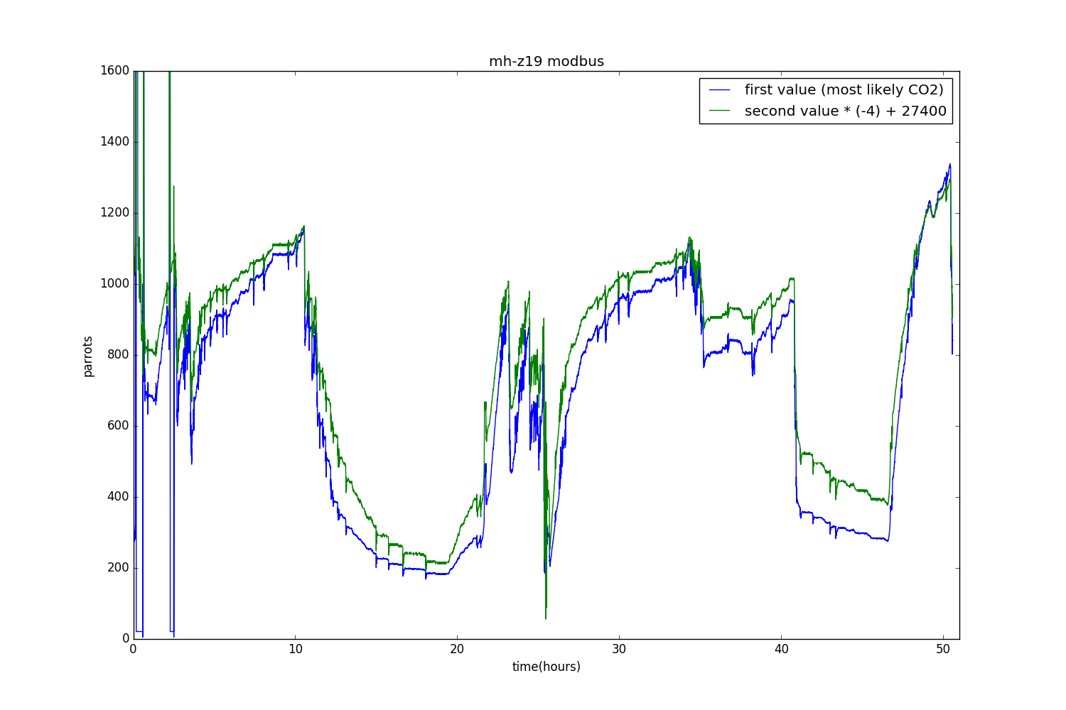
A natural question arises - perhaps one of these quantities is the very “raw” value that comes from the ADC and which sensor translates it to the CO2 estimate only by itself? If so, then it opens up great opportunities for recalibrating and improving the accuracy of the sensor, and perhaps, for using it not for its intended purpose. We will try to get the answer to this question (and some others) in the next series.
In kamentah suggestions and suggestions are accepted - how else to make fun of the MH-Z19 in the next article. True, I will not promise anything.
Yes, today we will again talk about all of us, our favorite Winsen MH-Z19 carbon dioxide sensor. No, there will be no repetitions *.
')
* nearly
As you can see,
First of all, of course, I connected it to the Arduin. Skopipastil (with the necessary changes) code from the article , the treasured numbers appeared on the small screen.
But while I copy-pasted, a worm of doubt crept into my soul - and why does this sensor produce nine bytes, and only two bytes per CO2 of them? Maybe he wants to tell me something else?
An Internet search brought me to such an interesting page . The author is experimenting with the MH-Z19 and reveals his reaction to undocumented (and documented) commands. He has not tried all the teams yet, so it will remain for our share where to frolic. This is what we will do.
First of all, let's deal with the “classic” team 0x86 (or simply 134), with the help of which we get the CO2 concentration. Revspace reports:
A response to command 0x86 typically looks like this:
0xFF CM HH LL TT SS Uh Ul CS
where
CM is the command repeated back
HH / LL is the CO2 ppm value, high / low part
TT is the temperature in degrees Celcius, plus 40. For example, when the temperature is 25 deg C, then TT = 0x41
Byte always has one bit set!
Uh / Ul is some unknown value, related to pressure? After booting the sensor, it starts out at 15000 exactly, then typically settles to about 10500.
Cs is the checksum
That is, the response of the sensor to this command also contains the temperature T (shifted by 40 degrees) and two quantities of unknown purpose — one-byte S and two-byte U. S takes values of two, and U when the sensor is started drops from 15,000 to just over 10 000
How to understand what the numbers S and U mean? Of course, you need to draw a graph! In any incomprehensible situation, draw a graph.
Sad technical details
And to draw a graph, it would be good to push the sensor readings into the computer. What I did with Serial.println (). Every five seconds, Arduin polls the sensor and writes its readings to the USB-UART, it remains only to read them on a computer and save to a file. I do it (in Linux) like this:
In another terminal window you can watch this file in real time:
It turns out such a sheet of numbers:
In each line - CO2, T, S, U (U is repeated twice - as two bytes and a two-byte number, do not ask why).
Now you can build graphics. I will do this with the help of ipython --pylab.
rlwrap cat | cu -l /dev/ttyACM0 > sensor_$(date '+%Y%m%d_%H%M%S').log Do not kick your feet
Yes, I know that you can just do cat / dev / ttyACM0> .., but for some reason it doesn’t always work for me, and sometimes this command ends silently. This command (rlwrap cat | cu -l / dev / ttyACM0) also appeals to me because it allows you to conveniently communicate with the microcontroller in an interactive mode (although in this case it is not necessary). Surely there are better means for this purpose, but, unfortunately, I do not know them.
In another terminal window you can watch this file in real time:
tail -f sensor_.log It turns out such a sheet of numbers:
... 1188 62 64 42 38 10790 1188 62 64 42 38 10790 1190 62 64 42 38 10790 1191 62 64 42 38 10790 1192 62 64 42 38 10790 1193 62 64 42 38 10790 1195 62 64 42 38 10790 ... In each line - CO2, T, S, U (U is repeated twice - as two bytes and a two-byte number, do not ask why).
Now you can build graphics. I will do this with the help of ipython --pylab.
y = map(lambda a: map(int, a.split()), open("sensor1.log", "r").readlines()) # , , yt = transpose(y) x = arange(len(yt[0])) / 720. # , figure() plot(x, yt[0]) # CO2 figure(); plot(x, yt[1], "g"); # T figure(); plot(x, yt[2], "r"); # S figure(); plot(x, yt[-1], "m"); # U So, the CO2 schedule:
In principle, it seems to be true. Only periodic bursts are grieving. It seems that this is because my sensor is just lying on the table, and at the slightest breeze, his readings go astray.
Temperature:
The moment when I opened the window is well noticeable. It moves up to 1 - 2 degrees, which is not bad for an undocumented opportunity. However, if you recall the principle of the NDIR sensor, you can understand that you should not expect great precision from the thermometer built into it. These devices measure the absorption of light in the far-infrared range, and to generate this light, the old kind Illich lamp is used, and you can even see through the windows how it lights up every five seconds (just such a moment is caught on QDPV). And this light bulb consumes a lot of energy and, as a result, heats the entire sensor, and how much it heats it depends on the short-term conjuncture of the air flow.
We approach the most interesting. S value:
Does not say anything? Me too. With grief, we will draw CO2 and S on the same graph and increase it slightly:
Aha Now everything is clear! When everything is good, S is 64, and when the CO2 sensor starts to sausage, it drops to 4. Thus, you can use S to find out how well the sensor feels and how accurate its readings are.
Left, as they say parachutists, the extreme value - U:
Unfortunately, the focus with the imposition here does little. It can only be seen that, as promised by the revspace, at the beginning it is equal to 15,000, and then falls to just over 10,000 (but it may fall a little after a long time). And once a day the cycle repeats.
But when I connected the sensor power supply not to 5, but to 3.3 volts of Arduin, the situation changed:
3.3 volts on arduin is taken from the LP2985 chip, which is a 160 milliamp linear stabilizer. And the bulb, judging by the articles on the Internet, eats about that much. When looking at the sensor, it is noticeable that the light bulb with this power supply flares up for a longer time than with five volts. And the value of U is one and a half times higher.
The following hypothesis emerges: the sensor automatically determines how long it takes to light a light bulb in order to get enough infrared radiation, and if there is not enough current, it burns the light bulb longer. And the value of U just reflects the time of the light bulb burning (or some other related value, for example, the energy expended).
To test this assumption, we power the sensor from a lithium-ion battery, which certainly can deliver much more current:
And indeed, U sometimes falls below 10,000! However, this is obviously not absolute proof, and after 24 hours everything becomes almost the opposite. So the hypothesis remains only a hypothesis, but I did not invent anything better.
UPD: Dear unsvp did solve the riddle of the U value. I give him the word:
the value of U, obviously, is the minimum value of the measured absorption of IR CO2 per day, in some internal units of measurement.
Add nothing, except that the schedule:
Why I did not think of it myself? It's simple. I drew a graph of four quantities at once and calmed down on this. And it was necessary to draw two values (as in the picture above), then the extraneous garbage in the face of S would not interfere with perception. Do not repeat my mistakes.
Perhaps add this: see a step of more than 1000 ppm at 48 hours? This sensor is so automatically calibrated. At the same time, the value of U has fallen compared to what it was before calibration. While it is obvious that the actual concentration of CO2 in this period only grew. The conclusion from this is very simple - the value of U is not quite the “raw” value of absorption, and is already calculated after adjusting for the current calibration, apparently representing a certain difference between the minimum readings in the current and previous calibration cycles.
In general, in my opinion, auto calibration (at least in the form in which it is implemented in MH-Z19) is evil. Revspace says that it can be disabled with the command 0x79: ABC logic on / off.
/ DFC
Well, with one team figured out. It's time to go on, but the article is nearing its end, and another 255 teams have not been tested!
In an article on revspace, the list of tested commands ends with:
command 0x89-0x8F
No response is returned, however the command 0x8d seems to reset the sensor.
command 0x99 (range)
...
In addition, commands with smaller numbers are not all checked. Thus, a little more than half of the total number of unexplored commands remains.
Without further ado, I decided to give commands randomly (more precisely, pseudo-randomly). And that's what I got:
... Command: 255 1 47 0 0 0 0 0 208 Response: 0 0 0 0 0 0 0 0 0 CRC: 00 CO2/t/s/u: 0 0 0 0 Command: 255 1 17 0 0 0 0 0 238 Response: 0 0 0 0 0 0 0 0 0 CRC: 00 CO2/t/s/u: 0 0 0 0 Command: 255 1 45 0 0 0 0 0 210 Response: 0 0 0 0 0 0 0 0 0 CRC: 00 CO2/t/s/u: 0 0 0 0 Command: 255 1 5 0 0 0 0 0 250 Response: 0 0 0 0 0 0 0 0 0 CRC: 00 CO2/t/s/u: 0 0 0 0 Command: 255 1 88 0 0 0 0 0 167 Response: 0 0 0 0 0 0 0 0 0 CRC: 00 CO2/t/s/u: 0 0 0 0 Command: 255 1 245 0 0 0 0 0 10 Response: 0 0 0 0 0 0 0 0 0 CRC: 00 CO2/t/s/u: 0 0 0 0 Command: 255 1 107 0 0 0 0 0 148 Response: 0 0 0 0 0 0 0 0 0 CRC: 00 CO2/t/s/u: 0 0 0 0 Command: 255 1 214 0 0 0 0 0 41 Response: 0 0 0 0 0 0 0 0 0 CRC: 00 CO2/t/s/u: 0 0 0 0 Command: 255 1 136 0 0 0 0 0 119 Response: 0 0 0 0 0 0 0 0 0 CRC: 00 CO2/t/s/u: 0 0 0 0 Command: 255 1 7 0 0 0 0 0 248 Response: 0 0 0 0 0 0 0 0 0 CRC: 00 CO2/t/s/u: 0 0 0 0 Command: 255 1 153 0 0 0 0 0 102 Response: 255 153 1 0 0 0 0 0 102 CRC: 102102 CO2/t/s/u: 256 0 0 0 Command: 255 1 146 0 0 0 0 0 109 Response: 0 0 0 0 0 0 0 0 0 CRC: 00 CO2/t/s/u: 0 0 0 0 Command: 255 1 72 0 0 0 0 0 183 Response: 96 249 2 211 215 212 17 215 204 CRC: 159204 CO2/t/s/u: 723 215 212 4567 Command: 255 1 51 0 0 0 0 0 204 Response: 93 151 80 143 212 255 255 255 217 CRC: 185217 CO2/t/s/u: 20623 212 255 -1 Command: 255 1 98 0 0 0 0 0 157 Response: 16 136 252 75 66 50 48 48 13 CRC: 9313 CO2/t/s/u: -949 66 50 12336 Command: 255 1 65 0 0 0 0 0 190 Response: 10 0 0 0 0 0 0 0 0 CRC: 0 0 CO2/t/s/u: 0 0 0 0 Command: 255 1 243 0 0 0 0 0 12 Response: 0 0 0 0 0 0 0 0 0 CRC: 0 0 CO2/t/s/u: 0 0 0 0 Command: 255 1 13 0 0 0 0 0 242 Response: 0 0 0 0 0 0 0 0 0 CRC: 0 0 CO2/t/s/u: 0 0 0 0 Command: 255 1 35 0 0 0 0 0 220 Response: 0 0 0 0 0 0 0 0 0 CRC: 0 0 CO2/t/s/u: 0 0 0 0 Command: 255 1 229 0 0 0 0 0 26 Response: 0 0 0 0 0 0 0 0 0 CRC: 0 0 CO2/t/s/u: 0 0 0 0 Command: 255 1 95 0 0 0 0 0 160 Response: 0 0 0 0 0 0 0 0 0 CRC: 0 0 CO2/t/s/u: 0 0 0 0 Command: 255 1 48 0 0 0 0 0 207 Response: 0 0 0 0 0 0 0 0 0 CRC: 0 0 CO2/t/s/u: 0 0 0 0 Command: 255 1 209 0 0 0 0 0 46 Response: 0 0 0 0 0 0 0 0 0 CRC: 0 0 CO2/t/s/u: 0 0 0 0 Command: 255 1 200 0 0 0 0 0 55 Response: 0 0 0 0 0 0 0 0 0 CRC: 0 0 CO2/t/s/u: 0 0 0 0 ... Here, the Command is what was sent to the sensor (the command number itself is the third number from the beginning), Response is what the sensor answered, you can not watch the rest (CRC is the calculated / actual checksum, CO2 / t / s / u is the result of the breakdown sensor response to four numbers, as if he responded to the "default" command).
As you can see, not a lot. Moreover, from some point on, the sensor refused to give out anything but zeros. The last thing I got from the sensor was:
Command: 255 1 134 0 0 0 0 0 121 Response: 0 0 0 0 0 0 0 0 0 CRC: 0 0 CO2/t/s/u: 0 0 0 0 Command: 255 1 130 0 0 0 0 0 125 Response: 242 98 200 201 207 216 178 130 33 CRC: 50 33 CO2/t/s/u: -14135 207 216 -19838 Command: 255 1 134 0 0 0 0 0 121 Response: 204 91 151 80 143 212 255 255 236 CRC: 93 236 CO2/t/s/u: -26800 143 212 -1 Command: 255 1 200 0 0 0 0 0 55 Response: 181 156 252 77 79 68 66 85 83 CRC: 241 83 CO2/t/s/u: -947 79 68 16981 Command: 255 1 134 0 0 0 0 0 121 Response: 13 10 0 0 0 0 0 0 0 CRC: 246 0 CO2/t/s/u: 0 0 0 0 Command: 255 1 216 0 0 0 0 0 39 Response: 0 0 0 0 0 0 0 0 0 CRC: 0 0 CO2/t/s/u: 0 0 0 0 And then zeros. I tried to enter commands sequentially, starting from 0x8e - again zeros. I tried to give the "standard" command 0x86 - zeros. Did I kill the sensor? In truth, all the conditions for this are present - I do not enter the undocumented commands, so I also connect the sensor interface directly to the five-volt arduine, although the datasheet directly says that it is designed for 3.3 volts.
First of all, I tried the good old recipe of any enikeyschik - turn it off and on again. I mean, I took it out and stuck it at the sensor plus the power supply while everything else was running. The sensor gave approximately the same as in the last quoted passage (but with slightly different numbers). Yeah, it means that the sensor is not quite dead and every time it says something, the Stirlitz guessed.
Then I thought about it a little more and figured it out before one truth - those zeros that we saw above are not the answer of the sensor at all. In fact, the sensor is silent, and my program draws what the arduin function of receiving n bytes has issued (that is, zeros). And if every time before accepting to make sure that there is something to receive, it turns out that there is nothing to accept. Is that except when the sensor has just rebooted.
It turns out that the sensor completely stopped perceiving any commands. Apparently, 5 volts on the serial interface were not in vain. Yes, the article did not work out somehow. Thank you all for your attention. We disagree, there is nothing to look at.
Oh, wait ...
See those numbers at the end?
13 10 Nothing like?
Of course, this is the good old line feed ! In other words, 0x0D 0x0A - so it is customary to translate a string, for example, in Windows (and in Unix it is easier to do it - 0x0A, because some files open lines in a notebook with a notepad).
So maybe the sensor wants to tell us something in human language? However, if this language is Chinese, it will not help me much. So let's hope that this is a more understandable language, and decipher the message according to the ASCII table:
print reduce(lambda a, b: a + b, map(lambda a: chr(int(a)), "255 255 255 250 24 220 207 254 77 79 68 66 85 83 13 10".split())) MODBUS Got as many as six letters. But that same sensor said when loading a little earlier:
print reduce(lambda a, b: a + b, map(lambda a: chr(int(a)), "96 249 2 211 215 212 17 215 204 93 151 80 143 212 255 255 255 217 16 136 252 75 66 50 48 48 13 10 ".split())) ` ] P KB200 The difference is obvious - the KB200 line has changed to the MODBUS line. The rest seems to be not a text at all, not even Chinese characters - if only because most of them change from time to time.
So what does the sensor tell us? On request, the KB200 search on the Internet produces a keyboard, core receiver, iron, changing table, PTZ camera control controller, a mixer, unless the hell does not produce a bald one. It is good, but it is not quite clear how to apply this knowledge to our case. Well, let's look for MODBUS. This time, Wikipedia itself is at our service:
Modbus is an open communication protocol based on the master-slave architecture. It is widely used in industry for organizing communication between electronic devices. It can be used for data transmission through serial communication lines RS-485, RS-422, RS-232, as well as TCP / IP networks (Modbus TCP).
The hypothesis suggests itself: after one of the undocumented commands, the sensor has switched to the Modbus protocol and now with available methods it notifies us about it. Since there are no other options foreseen, we will deal with direct verification of this hypothesis, that is, we will try to contact the sensor via Modbus.
On the Internet, a Modbus implementation for the Arduin was found. But that's bad luck - Arduino Leonardo is not supported, and I have, by horrible accident, Leonardo.
But, as I soon realized, this is even for the better. Modbus protocol is as simple as a penny. And besides, it painfully resembles the “native” protocol MH-Z19. So why drag all the nastiness out of the Internet and painfully understand it when you can in two minutes (well, two hours) realize everything you need yourself?
So, earlier we, wanting to find out the readings, asked the sensor to issue them as follows:
0xFF, 0x01, 0x86, 0x00, 0x00, 0x00, 0x00, 0x00, 0x79 Or in decimal terms:
255, 1, 134, 0, 0, 0, 0, 0, 121 Where 255 is the magic number, 1 is the address of the sensor, 134 is the command, 121 is the checksum byte.
And what will it look like in Modbus? There will be no exact match, but you can do this, for example:
1, 4, 0, 0, 0, 4, 213, 197 1 - sensor address.
4 - team number. Commands in Modbus can be counted on the fingers, and so far we will be interested in only two of them - 3 and 4. For reasons hidden in the darkness of ages, they are called Read Multiple Holding Registers and Read Input Registers, and in fact give the command to read the specified the number of two-byte numbers at a given address. Command 3 reads numbers available for reading / writing, and command 4 reads only.
0, 0 - the address at which we are going to read (in this case, 0). If you specify the same address with the command 3 or 4, we will get different results in general.
0, 4 - the number of numbers that we want to read (in this case, 4). There is a funny moment. Although you can set this number up to 65535, in fact, the protocol allows you to read no more than 125 numbers at a time. And all because the response indicates the number of bytes of information sent, and it takes only one byte (and the numbers are two-byte). Also, as I understand it, the length of the response itself is limited to 255 bytes.
213, 197 - two bytes of checksum ( CRC16 ). In general, this is the most difficult moment in all of our implementation. To tell the truth, I didn’t even understand how it’s considered, but simply copied the code from here . Since there is a different CRC16 sea, it is necessary to take a responsible approach to the choice of function. Check whether a particular function is suitable for Modbus, for example, here .
That's all we need to know about Modbus. At least for a start.
Although you have already guessed for a long time that my appeal to the MH-Z19 on Modbus was completed with success, but let's pretend that the intrigue remains. So far, we still do not even know what our sensor address is (although “in the original” it is equal to 1, it’s far from a fact that it is the same in Modbus). So, we need to repeat the command with different addresses (there are only 255 of them) and see which of our sensors will respond:
... Command: 254 4 0 3 0 1 213 197 CRC: 213 197 Response: Command: 255 4 0 3 0 1 212 20 CRC: 212 20 Response: Command: 0 4 0 3 0 1 192 27 CRC: 192 27 Response: Command: 1 4 0 3 0 1 193 202 CRC: 193 202 Response: Command: 2 4 0 3 0 1 193 249 CRC: 193 249 Response: 1 132 2 194 193 Command: 3 4 0 3 0 1 192 40 CRC: 192 40 Response: Command: 4 4 0 3 0 1 193 159 CRC: 193 159 Response: ... It seems that the address is 2. I repeat several commands with address 2 - there is no answer. I change the address to 1 - there is an answer! Thus, the address of the sensor is the same as it was - 1.
And why in the above passage got address 2? Here again the code of my code comes out. After sending the command, I check if there are any bytes at the reception. But since I do it right away, the sensor does not have time to send anything, so the response of the sensor is accepted by the program only in the next cycle. Which can be observed in the above log - the first number in the answer is 1, and it just indicates the address of the sensor. I got around this trouble by simply adding a delay of 50 milliseconds before accepting an answer.
Consider the sensor response to our command:
1 132 2 194 193 1 - as we found out - the address of the sensor.
132 - command code and error code. If there was no error, this number would be the same as the sent command - that is, 4. But an error occurred, which is indicated by the high bit set to 1, so the number became 4 + 128 = 132. Therefore, by the way, a command in Modbus cannot have a number greater than 127 - for such a command, a successful completion code would be the same as an error code.
2 - error code.Says what kind of error occurred. As says wikipedia, 02 - Address data specified in the request is not available. So, there is no fish at this address and there is nothing to catch. We will try other addresses.
194 193 - CRC16.
Now, finally, it’s time to go through the address space of the sensor in order to understand where the fish is. I did this simply - I sent a command to read one number with a new address every 0.1 seconds. Since the addresses are 65536, this process is completed in approximately two hours. The results in brief are as follows:
Command 1 (Read Coils) - with any address error 2.
Command 2 (Read Discrete Inputs) - with any address error 2.
Command 4 (Read Input Registers) - with any address error 2.
Team 3 (Read Multiple Holding Registers) gives success at addresses from 0 to 289.
Commands to write values (for example, 6) seem to work, but it seems that the recorded value is soon replaced by what it was. But close this question is not investigated.
So, the search circle narrows down - we need numbers on command 3 and addresses from 0 to 289. You can get an idea of the rich inner world of the sensor using these lines:
Command: 1 3 0 0 0 64 68 58 CRC: 68 58 Response: 1 3 128 0 0 0 255 0 1 0 1 0 255 0 255 0 255 0 255 0 255 0 0 0 0 0 0 0 0 0 0 0 0 0 0 0 0 0 0 0 0 0 0 0 0 0 0 0 0 0 0 0 0 0 0 0 0 0 0 0 0 0 0 0 0 0 0 0 0 0 0 0 0 0 0 0 0 0 0 0 0 255 255 0 255 0 0 0 0 0 0 0 0 0 0 0 0 0 0 0 0 0 0 0 0 0 0 0 0 0 0 0 0 0 0 0 0 0 0 0 0 0 0 0 0 0 0 0 0 0 0 158 124 Command: 1 3 0 64 0 64 69 238 CRC: 69 238 Response: 1 3 128 0 0 0 0 0 0 0 0 0 0 0 0 0 0 0 0 0 0 0 0 0 0 0 0 0 0 0 0 0 0 0 0 0 0 0 0 0 0 0 0 0 0 0 0 0 0 0 0 0 0 0 0 0 0 0 0 0 0 0 0 0 0 0 0 0 0 0 0 0 0 0 0 0 0 0 0 0 0 0 0 0 0 0 0 0 0 0 0 0 0 0 0 0 0 0 0 0 0 0 0 0 0 0 0 0 0 0 0 0 0 0 0 0 0 0 0 0 0 0 0 0 0 0 0 0 0 0 0 27 165 Command: 1 3 0 128 0 64 69 210 CRC: 69 210 Response: 1 3 128 0 4 0 0 0 0 0 0 0 0 0 0 0 0 0 0 0 0 0 0 0 0 0 0 0 0 0 0 0 0 0 0 0 0 0 0 0 0 0 0 0 0 0 0 73 82 0 153 0 8 0 17 0 177 0 19 0 19 0 196 0 18 0 20 0 214 0 18 0 21 0 232 0 18 0 22 0 250 0 5 0 24 0 255 0 5 0 18 1 4 0 3 0 23 1 7 0 25 0 0 0 0 0 0 0 0 0 0 0 255 0 255 0 1 0 0 0 5 0 0 0 0 0 0 0 0 0 0 137 122 Command: 1 3 0 192 0 64 68 6 CRC: 68 6 Response: 1 3 128 165 165 0 165 0 0 255 255 255 255 255 255 255 255 0 15 3 232 0 100 0 90 0 0 0 63 128 0 0 255 0 15 0 5 0 10 0 5 0 5 0 30 0 15 0 0 0 20 0 40 0 60 0 80 0 100 0 0 0 5 0 5 3 232 255 255 255 255 165 165 0 165 0 0 16 3 0 6 0 0 0 0 0 0 0 0 0 0 0 0 0 0 0 0 0 0 0 0 0 0 0 0 0 0 0 0 0 0 0 0 0 0 0 0 0 0 0 0 0 0 0 0 0 0 0 0 0 0 163 198 True, the archive contains numbers only up to the address 255. Here again, 1 3 is the address and command, 128 is the number of bytes transferred, two bytes at the end are CRC, and everything else is the contents of the memory.
From all this magnificence, we are obviously interested in those addresses whose contents change with time. And here the sensor had two news for me - good and bad. Good - there are such addresses. And the bad - there are only two - 261 and 264. Compare with the “past life”, when four numbers were given at once to one team! I already had my lip rolled out - I thought I would get access to all internal variables. Well, two so two.
Time to build graphics again!
Value at 261:
It looks like a CO2 concentration. It can be seen when I tried to breathe on the sensor. True, the minimum value is noticeably lower than the “reference” 400 ppm, so the calibration leaves much to be desired. One way or another, the sensor is declared resurrected.
The value at address 264:
Approximately the same, only on a different scale and inverted.
And both values on the same graph:
A natural question arises - perhaps one of these quantities is the very “raw” value that comes from the ADC and which sensor translates it to the CO2 estimate only by itself? If so, then it opens up great opportunities for recalibrating and improving the accuracy of the sensor, and perhaps, for using it not for its intended purpose. We will try to get the answer to this question (and some others) in the next series.
In kamentah suggestions and suggestions are accepted - how else to make fun of the MH-Z19 in the next article. True, I will not promise anything.
Source: https://habr.com/ru/post/401363/
All Articles