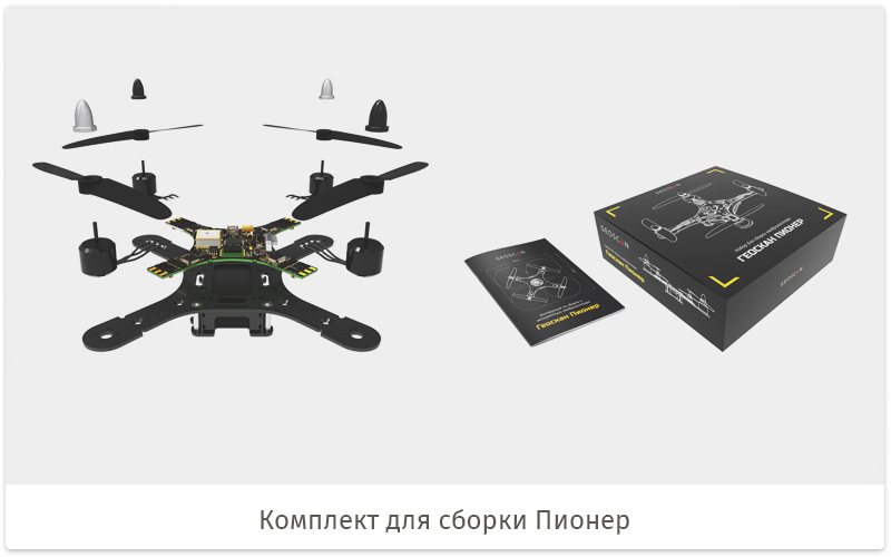
Geoscan Pioneer - "school" quadrocopter
In the article we will consider the electronic part of the new quadrocopter Geoscan Pioneer, which is intended for teaching robotics. We will talk about the creation of a copter, or rather, about what kind of experience we received and what changes we made to the project. In conclusion, we will share our plans for the future.
1. Why is a quadrocopter created in Geoscan for training
Unmanned aerial vehicles (UAVs), in particular, multi-rotor systems, are increasingly being used to solve many applied problems. Their presence can be seen in many areas, for example, in aerial photography, cargo delivery, video filming from the air, monitoring of objects, as well as in races (drone-racing).
At the same time, there is a shortage of professional personnel in the rapidly developing unmanned aircraft industry. Technical personnel is best prepared from the school. Only having passed all stages: from design to operation and modernization - can become a true professional in his field and give another turn in the development of the industry, both in technological terms and in terms of involving more and more related areas in the industry and solving more and more applied tasks. .
')
It can be argued that the use of the quadcopter by schoolchildren, students and amateurs as a flying robot to learn the basics of developing, operating and modernizing a UAV is an interesting topic for us. In consequence, this may lead to the creation of a new educational standard base.
We believe that the following topics are the most interesting to study:
Programming of control systems, creation of orientation and navigation algorithms in space, recognition of the environment;
Electronics - connecting sensors and studying the principles of their work, studying the design of aircraft systems;
Construction of the frame and mechanics, as well as the study of the electro-mechanical parameters of the Kopter for the optimization of flight modes in solving various problems;
Control of the copter in both pilot mode and UAV operator mode. That is, manually or automatically.
Thus, many interesting tasks are being formed that can be provided to be solved by the younger generation in the framework of educational circles, contests and competitions.
Based on the above and already on the existing experience of creating UAVs in the company Geoscan, we decided to bring these ideas to life, by creating a software and electronic platform.
It is worth noting that in order to simply program a flying robot, you need a navigation system. And if on the street this problem is solved by the use of satellite navigation, then indoors this task does not have an unambiguous solution. Considering that it is not always possible to work outside due to the weather, the surrounding area or safety, navigation in the room is simply necessary. What navigation system we choose will be described below.
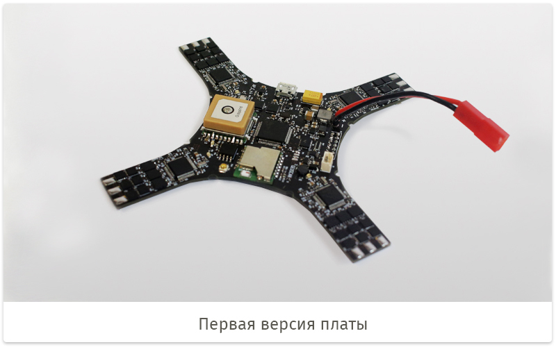
2. The first version of the electronics "school" copter
To create a small kopter, it is necessary to reduce the weight and size of the electronics to a minimum. To do this, it is logical to apply a single-board solution containing autopilot (AP) with sensors, motor controllers, radio communication, power sources and necessary connectors. "Single board" simplifies the combination of electronics with the frame and reduces the number of wires to a minimum.
Brushless motors are used due to a number of advantages compared to the collector ones. Such motors are more efficient and reliable, and a large torque of relatively low weight, eliminates the use of a gear on the screw. A certain complexity is the development of speed controllers for brushless motors. But thanks to the experience in the development of "adult" UAVs, this did not become a big problem. Of the minuses of the selected rotor-motor group, only the cost of the motors and regulators can be noted, but it is justified by the flight time, the good speed characteristics of the copter, the ability to move a greater payload, and less will have to mess with buying and replacing the failed motors.
Thus, we approached the creation of a prototype board for a small copter. We will not pay much attention to this board, but only note its main flaws, which are not small, primarily because of the very modest development time of three weeks.
During the initial design, we wanted to try the maximum functionality of the kopter, therefore the magnetometer and the satellite navigation module were placed on the board, which turned out to be inoperative due to insufficiently good electromagnetic compatibility with the board. The magnetometer was too close to the power conductors and when current passed through the conductor, the magnetometer gave incorrect information. Due to the insufficient screen area of the ceramic antenna, the GPS receiver found an insufficient number of satellites for navigation.
For ease of connecting a quadrocopter to a computer, a Wi-Fi modem was used. Using this interface for telemetry and control is problematic if it is intended to operate in a noisy environment, for example, at exhibitions or other public events where there are a lot of 2.4 GHz devices. In addition, the module showed unstable network performance.
From the point of view of operation, everything also turned out not quite smoothly. Firstly, the phase wires of the motors had to be soldered to the board, since there were no connectors for them. The difficulty lies in the need to have skills in working with a soldering iron and the ability to confuse the order of wires, which leads to the wrong direction of rotation of the motor, and also complicates the assembly and disassembly. Secondly, it was not possible to make convenient mounting holes on the board, which had a bad effect on the reliability and practicality of attaching the board to the frame. Thirdly, the interface connector in the form of standard "pins" with a step of 2 mm is not always convenient to use when connecting multiple devices.
Among other things, the size of the board turned out to be more than expected due to the one-sided installation of the elements (except for a small number of regulator elements on the bottom side).
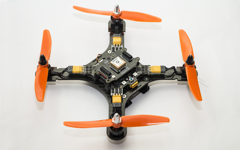
Nevertheless the kopter turned out working. The autopilot and controller firmware have been transferred from our “big” copter . By slightly adjusting the coefficients of the control loops, we forced the copter to perfectly cope with its main task - to fly. With 1306 3100 kV motors, 5 "screws and a LiPo 2s 1300 mAh battery, the copter flies 15-16 minutes, and with a GoPro3 (80 g) it lasts about 10 minutes.
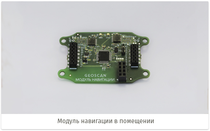
The flight was implemented in the Marvelmind ultrasound (US) navigation system. The system consists of two types of ultrasonic beacons: stationary and mobile. At the same time, the movable beacon of the system attached to the copter outputs 3 position coordinates to the autopilot with a fairly low accuracy (± 5-10 cm) and the control system we created combines this data with the gyro and accelerometer data, and controls the spatial position of the copter.
3. Ideas when creating a new version
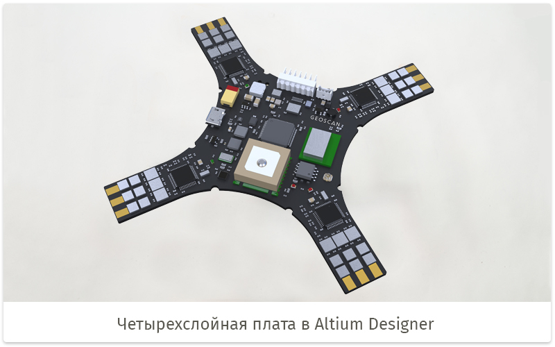
When approaching the new version of the board, it became obvious to us that it was necessary to make a number of improvements. We have thought over the concept of the project in more detail, as a complete vision of the areas and methods of using the kopter has appeared. The main idea was to leave only the necessary components on the board and make a kind of “motherboard” to which the modules that define the functional purpose of the copter will be connected. An example of such a module can serve as a satellite receiver with a compass for navigation on the street.
Now the new board contains the main controller AP with sensors - an accelerometer, a gyroscope and a barometer. The barometer is needed for the altitude hold mode, which greatly simplifies the control of the copter during manual operation. To store flight logs and autopilot parameters we use a separate flash memory chip.
All electronic components on the board and expansion modules are powered by three voltage converters: 5 V (for modules, LEDs, PPM / SBUS receivers), 3.3 V (for modules and microcircuits on the board), and another 3.3 V separately for sensors. Input voltage is from 6 V to 14 V, which corresponds to a lithium-polymer battery with two or three “banks” (2s-3s).
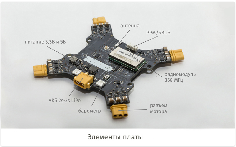
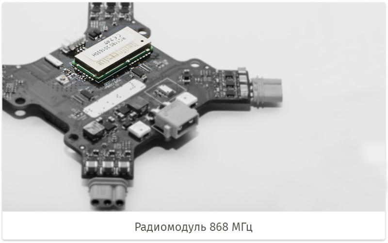
Communication with a PC via a radio channel or USB. To reduce development time, we used a ready-made radio module from Radiocraft at 868 MHz with a power of 25 mW.
The radio module is provided with a chip antenna on the board, as well as a connector for an external antenna. However, to use the external antenna connector, you will have to work with a soldering iron. It is assumed that the ordinary user will be enough chip antenna. To connect your PC to the copter by radio, you need to use the supplied USB modem supplied in the kit.
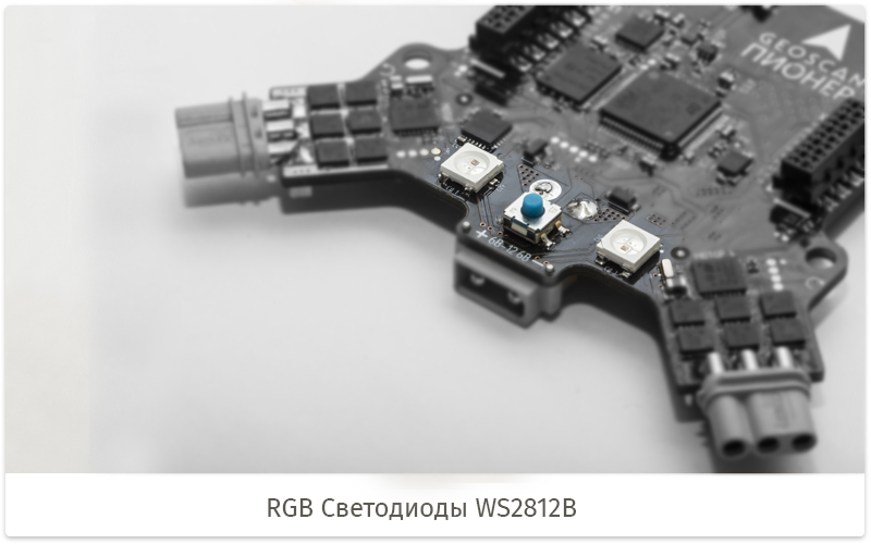
The indicators of various events are the R28 LEDs WS2812B that are controlled. It is possible to connect additional LEDs, except for those that are on the board.
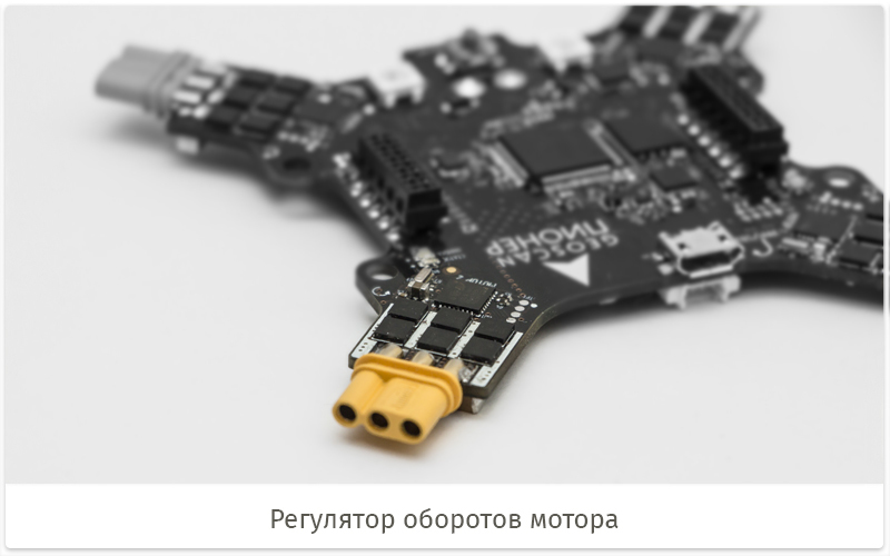
Motor speed regulators are able to withstand a current of 20 A and have the ability to actively brake, which has a positive effect on the dynamics of the control of the copter.
The supply voltage is within 2s-3s of LiPo batteries. The regulators are connected to the AP via UART, and not via the PWM signal. This has a good effect on interference resistance. The size of the regulators is reduced, compared with the first version, due to the more compact cases of electronic components. In addition, we made a two-sided assembly of components, which also reduced the size of the board.
Now on the board appeared "human" mounting holes for easy installation to the frame.
There are more useful connectors. Now you do not need to solder the wires of the motors to the board. Expansion modules are connected via two connectors on top of the board, and the position of the module cannot be confused due to the different number of pins and the design of the connector itself. TE Micro-MaTch connectors are selected for protection against mechanical damage. Unlike the 2.54 mm pins, they are not easily damaged when dropped or neglected. It is also possible to connect modules via an extension cable to allow the module to be carried out, for example, down the driver. The following interfaces are connected to these connectors: UART, SPI, I2C, several GPIO, signal for connecting additional controlled LEDs and power supply 3.3 V and 5 V. The logic level of the interfaces is 3.3 V by default, but can be changed to 5 V if desired.
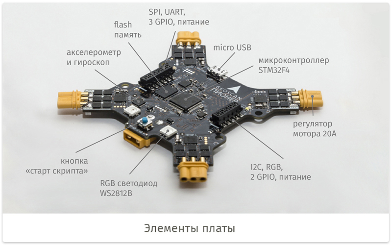
The button is programmed by the user or used by default to run the script.
A little bit about the software component of the platform. The autopilot STM32F4 microcontroller firmware is written in C ++ and runs on RTOS NuttX . The firmware is closed, but the user can write his code in the scripting language Lua .
In general, we chose from several scripting languages: Python, JavaScript ( IoT.js ) and Lua. The standard implementation of Python is difficult to use under the MK, because of its too large size. We considered the version with MicroPython, but it did not suit because of the possibility of direct access to assembler instructions. And we would not want to provide access to them to an ordinary user. JavaScript has redundant functionality and would have to work to remove the excess. Lua is a very popular language, easily extensible with C ++, and has implementations suitable for us.
The script can contain control algorithms or simply a sequence of actions, receiving and processing data from sensors, managing payload, etc. In general, provides a wide functionality of interaction with a flying robot, which can be used for research, competitive or amateur tasks. The script can be written and uploaded to the copter using a special application, but you can also generate code using Google Blockly .
You can download the script via USB wire or radio channel. The application on the PC displays telemetry information, which allows you to judge the status of the copter. And, of course, there are controls and settings of the robot.
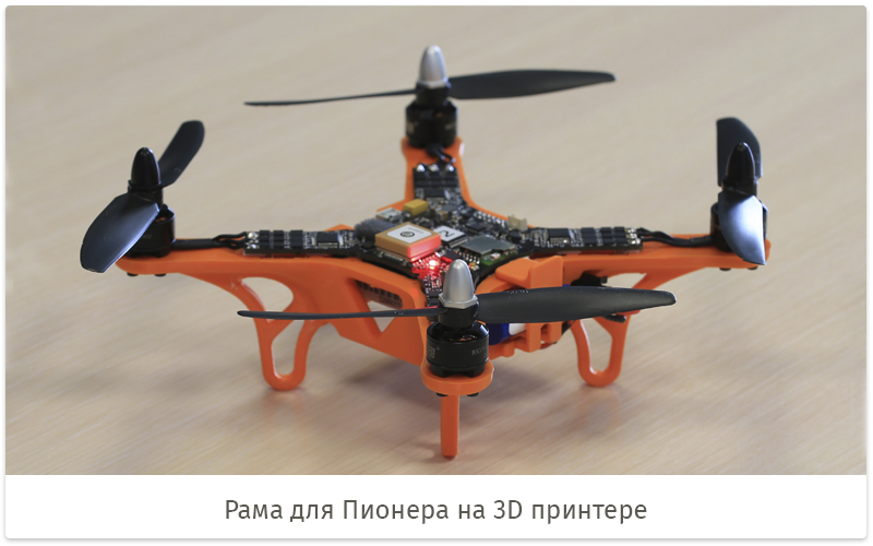
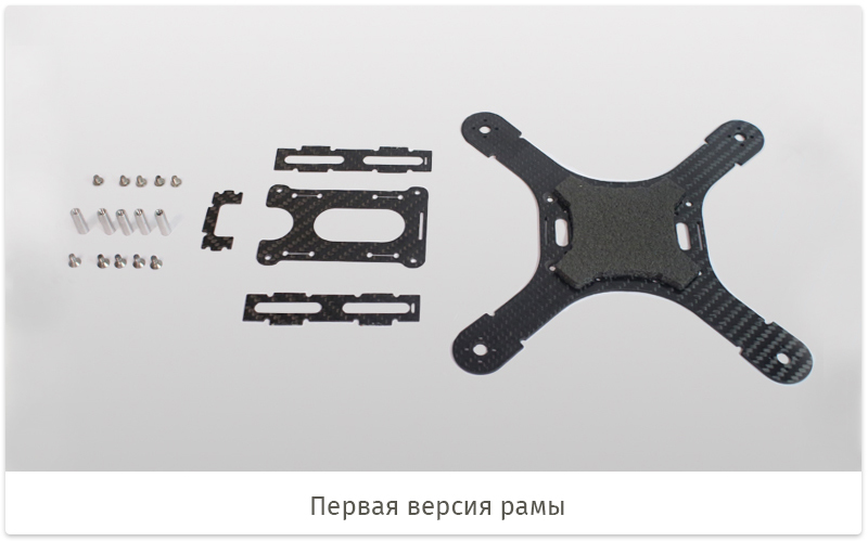
The frame, at the moment, is made of carbon or fiberglass by milling plates. It is assembled from a small number of parts and has a battery compartment.
Optionally, you can put the chassis and screw protection. Now in the development of a frame made of plastic, which will be manufactured using injection molding technology.
4. Expand the functionality of the modules
As mentioned above, the board has the ability to expand with plug-ins. The main modules are as follows:
Navigation module - a receiver for its own indoor positioning system for ultrasound.
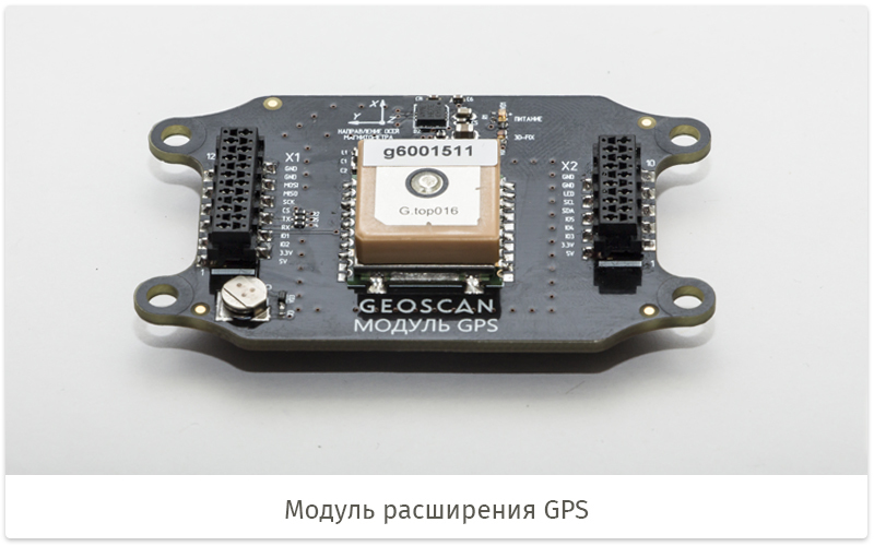
GPS module - positioning on the street by satellites. Also has on board a magnetometer for orientation along the course.
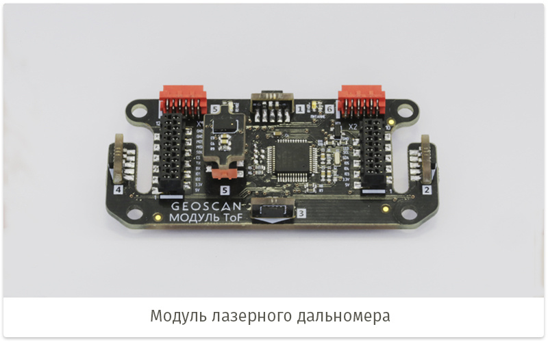
Module ToF - receives information from several ToF distance sensors directed in different directions, which allows to detect obstacles.
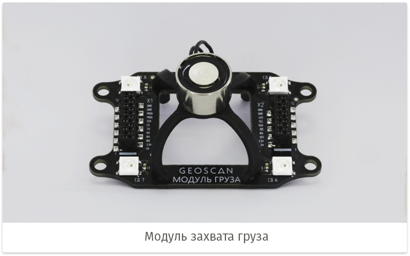
Load Module - equipped with an electromagnetic load seizure and LEDs for indication and lighting effects.
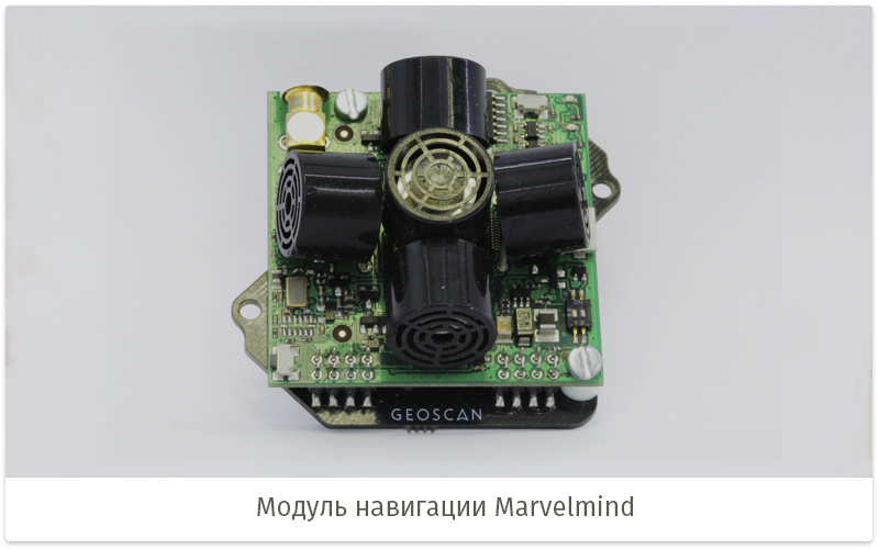
Marvelmind module - adapter for positioning system from Marvelmind.
OpenMV module - an adapter for the OpenMV computer vision camera .
Module Sonar - provides the possibility of obtaining height using an ultrasonic sensor.
WiFi module - adds a WiFi interface.
Bluetooth module - adds Bluetooth interface.
Of course, there are many other modules that we plan to create in the future.
5. Application in practice and future plans
Promo video Geoscan Pioneer
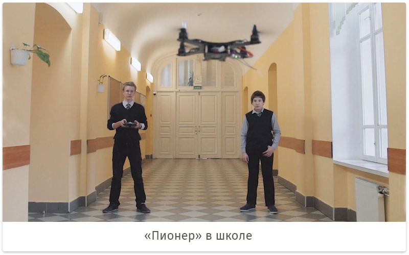
We carried out several deliveries of the Pioneer to various educational institutions. They were made on the basis of the first version of the board, so the supplies were more experimental. But nevertheless, the kopter quite approached as the assembly designer and for training in skills of piloting.
Piloting competitions were held with the participation of the Pioneers in Alferevo during the AeroNet 2016 conference.
Like a flying robot, Pioneer drew attention to himself at the robotics festival Robostinist . There passes the test of the flight of the eight, which, in fact, the copter successfully coped. The system worked on the basis of UZ navigation.
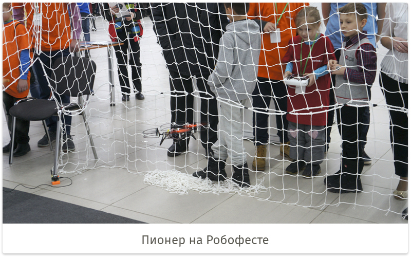
A platform was made with a safe space in the form of a frame with a grid, where all visitors to the festival had the opportunity to steer a copter. In this case, the control system did not allow the copter to be moved outside the permitted zone.
Today, we are working on the production of the first lots of Pioneers, developing new expansion modules, designing a plastic frame for casting and completing the creation of our ultrasound navigation system. And the presentation of our Pioneer is also planned. The location and time of the event will be available on the Geoscan website.
Source: https://habr.com/ru/post/401349/
All Articles