Happy end for hot end, or our strength - in swimming trunks

Good day to you, dear geeks and sympathizers! What can a geek equipped with a 3D printer dream of on cold winter evenings? Probably on the sunny shores of Copacabana. Or about the bottomless eyes of the sultry Brazilians. But in Copacabana, rampant crime, and the spouse does not support the idea of polygamy, even in a rudimentary form. So you have to provide yourself with hot things yourself, and publish the results for igniting the discussion.
When I was young and naive, 3D printers were industrial and large, microprocessors were expensive and scary, and with a single stamped key, you could fix the whole large one.
When, back in 2010, the 3D revolution named after Josef Pryusha came into my quiet home as a self-made printer, I ran into one of the greatest problems of bulk printing - the lack of performance of standard hot-ends.
')
After a brief analysis of the hot end designs, I identified the following weak points (of course, this is purely my personal opinion, never claiming to be true, true or consistent with reality):
1. Considerable distance from the heating element to the channel (slow heating of the channel)
2. The channel is a stainless steel tube, onto which an aluminum block is screwed, into which a heating element is inserted (tremendous thermal resistance at the connections, and a stainless steel with its low thermal conductivity)
3. Considerable distance from the channel to the thermistor (slow response to changes in the channel temperature)
4. Low heat capacity of the aluminum block, respectively, large temperature fluctuations when changing conditions (fan on / off, changing the filament feed rate, etc.)
To begin with, a primitive stone-ax was made, my very first hot end:
Design: the channel is drilled in the integral copper block, the nozzle is soldered directly. Heating is made with nichrome wire in fiberglass insulation, wound on the copper block directly. Winding covered stove putty. The thermistor is located in the hole drilled in the block parallel to the channel. A stainless steel thermal barrier is sandwiched between the heating element and the pneumatic connector, and a teflon liner is located inside the thermal barrier.
Practice has shown that the hot end works very precisely in terms of temperature, there was no sticking and jamming of plastic. The problem arose later when I made a printer with high-speed kinematics: while the end stopped keeping up with the events. It is time to conduct experiments and read the Internet. The best Internet on this topic was recognized. Materials were purchased and hot ends were collected with various channel lengths:
It was boring and long, but practical tests convinced me of the advantage of long channels. As they say, in this case size matters. In addition, I learned how to solder dissimilar materials with silver-containing solder and finally learned the Zen of a Chinese lathe.
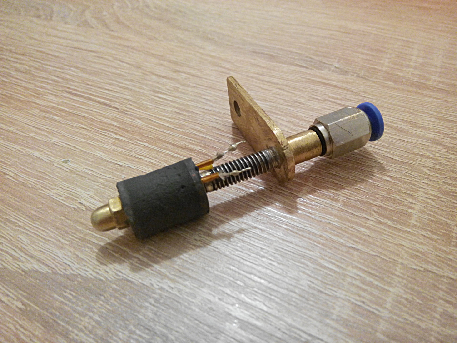
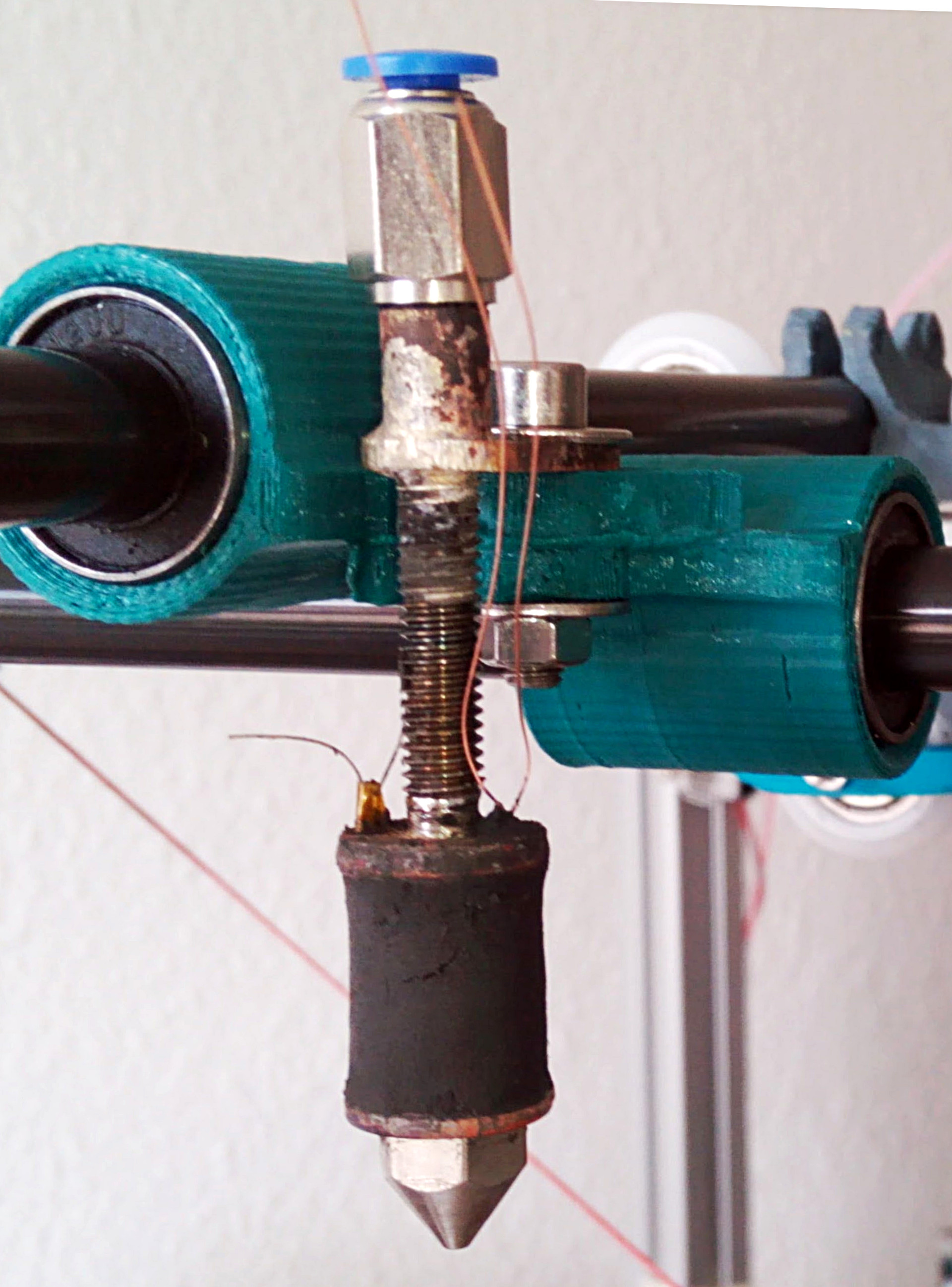
The result of numerous experiments and multi-second reflection was the following construction of a hot end:
Let's go through the picture from top to bottom:
The bowden teflon tube extruder (outer diameter 4mm, inner 2mm) is inserted into the pneumatic connector with an M6 thread screwed into the upper part of the brass threaded sleeve. The lower part is wound on a thermal barrier made of stainless steel and sealed. Thermal barrier is the most time consuming part of a hot end:
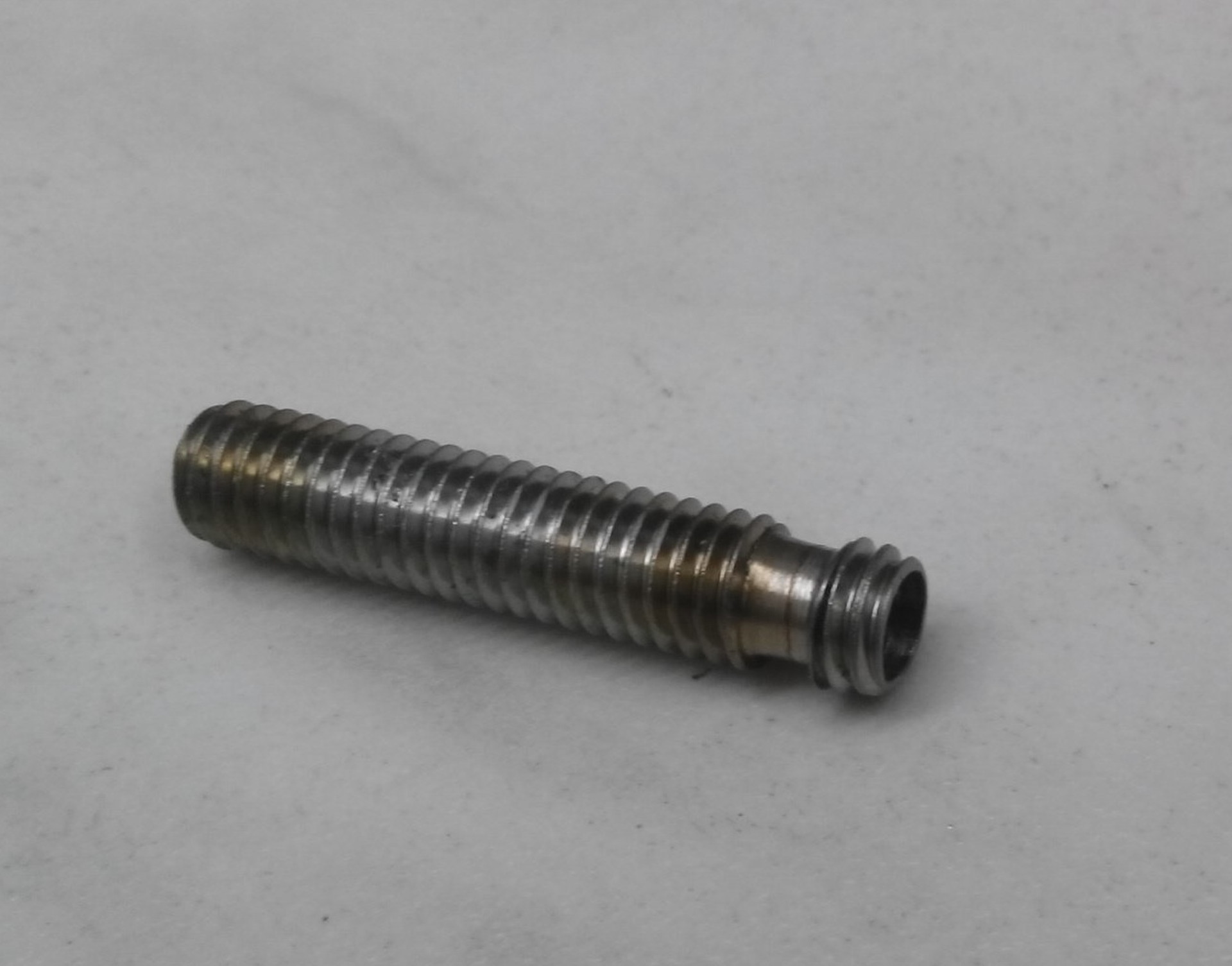
To manufacture it, it is necessary to cut 5-6 millimeters of thread at one end on the M6 set screw (screw material is stainless steel), leaving two full turns intact. After that, carefully drill the bolt with a 4mm drill (stainless steel is drilled extremely badly). What is the meaning of this action? The fact is that the core diameter (the central part without thread) of the M6 bolt is 4.773 mm according to the standard. Considering the fact that the hole when drilling with a 4mm drill will be about 4.2-4.4mm in diameter (depends on the machine and experience), we get the walls of the thermal barrier (in the part where we cut the thread) with a thickness of 0.18 to 0, 28mm. Together with the low thermal conductivity of stainless steel, thermal insulation of such thin walls is so effective that no additional cooling of the barrier is required. The remaining thread serves as a kind of radiator fins. With its lower end with two turns of thread, the thermal barrier is screwed into the copper heater block and sealed with high-temperature solder (the one with tin will not work)). You can do it without threading, but it was easier for me. Inside the barrier is a Teflon tube with an outer diameter of 4 and an inner diameter of 2mm.
Attention: in principle, Teflon is not designed to work at a temperature of more than 260 ° C, so if you want to print with something very high-temperature type of polycarbonate, it is better to lay a ring of 5-7mm height between the heater and Teflon.
The copper heater block itself is similar in shape to a regular wooden spool of thread. In its upper part, a hole 2.5 mm deep coaxially with the channel is made, with M6 thread for fixing the thermal barrier. In addition, two through longitudinal holes are drilled in the upper rim for the nichrome winding leads and one blind hole with a diameter of 2.5 mm at an angle to install a thermistor. It is important to ensure that the thermistor is located near the channel, it is very conducive to the correct picture of the world in the printer’s brain. The thermistor before installation is smeared with a furnace putty or silicone, so as not to dangle. The central channel in the block is made with a 1.8mm drill and is brought to a diameter of 2mm by conical sweep from the side of the thermal barrier.
The lower part of the heating element in the picture can have an M4 thread, then the nozzle will be home-made from a M4 steel screw and a brass cap nut (it is a pleasure to drill 0.3mm holes!) Or M6, then you can install any standard nozzle.
Winding nichrome in fiberglass insulation - an elementary act, a special description is not worth it. The finished winding is plastered with a furnace putty or high-temperature silicone.
Here is one of the earliest copies:
I stopped at a clean, non-marketing channel length of 25mm:
Now proofs in terms of functionality.
This is the normal speed for ABS:
This is what went PETG. It's dirty, because it was necessary to quickly, the settings are appropriate :)
Nylon. They say it is difficult for them to print:
Abs. If you do not rush, it turns out very clean:
Here again is PETG. The speed of the extruder motor shows how fast my hot end melts the filament:
For sweetness - a comparison of figures made of ABS (green) and PETG (red), both figures are printed with a single-layer wall, with a spiral vase:
Published under the WTFPL license.
Well, and traditional: Have fun!
Source: https://habr.com/ru/post/401177/
All Articles