On the theory of Hotand / Hotend_theory. Summary of results

Happened! Based on the calculations, 2 parameters were changed and nylon / nylon printing went very well.
As you know, I study and design heads for the hotend - that is, the heads of FDM 3D printers. There is such a direction in the design of these printers as RepRap. The essence of the idea is the design of 3D printers that can make parts for reproducing themselves, which actually means the abbreviation RepRap.
')
So, from time to time I look at reprap.org/wiki/Hotend_theory - an article on the theory of these very heads. It used to be quite small. Now more, but mostly questions. Some of them (both) I closed for myself a year and a half ago. Truth arose many others. So I have something to write.
This is a preliminary message, without formulas, calculations, pictures (there are pictures, but few) and graphs. Pure lyrics, without formulas, some conclusions. Without specific tips and schemes of heads - the last option is even nothing, but the essence is in the knowledge gained. Now I am more confident in my calculations and they even seem to work, why I am writing. To celebrate. Something remains to be verified, especially for the turbulator. This is a little thing in the head that can increase the performance of the head in liquid plastic at times with all other parameters being equal.
So, more to the point. After accumulating some knowledge in designing the heads, mainly for the test bench, I decided to change the head in my printer. There was also my home-made, only very old and with capron it printed not very well. In the manufacturing process, according to my calculations, I had to rework something in the design for manufacturability and refine and supplement my calculation methods. According to the results - I made the head. When trying to print, for some reason it was not possible to achieve the adhesion of the polyamide melt to the table covered with Kpton.
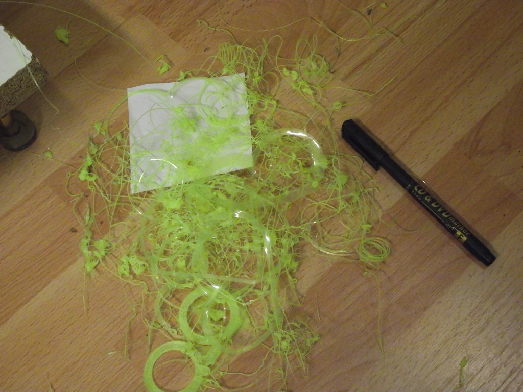
A bunch of scraps of non-sticky first layers. We must not guess, but count!
Since I know my printer's equipment quite well, I was sure that the question was in the head. During a series of experiments on the extrusion of fishing line into the air, I noticed a very interesting effect.
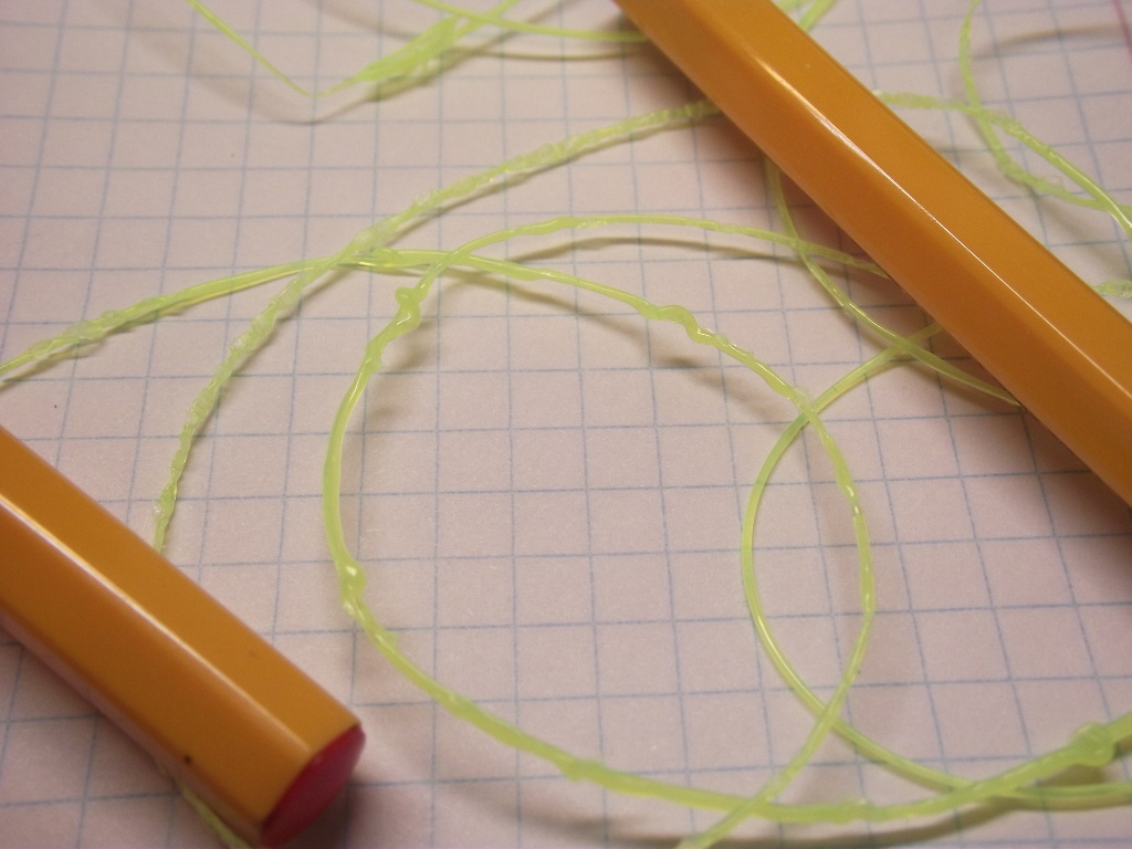

Hot, alive, there was a noticeable thread in the center of the melt stream, which occurs when the extrusion rate increases, and the turns of liquid viscous melt are strung on it.
Also in the process of this operation, I well remade the file to calculate the heads. Now it allows not only to calculate the heat fluxes from the head, from the radiator, to the place of fastening of the head, heat carried away with plastic (more clearly to say the cold brought by the filament), but also to warm the filament in depth, over time, in the case of overheating higher than the working temperature (That is, the heating temperature is higher than the one needed for melting, but we count the time when the center reaches the working temperature).
The calculations showed that the formation of this thread itself is a direct consequence of the non-melting of the filament to the center. Moreover, it is quite accurate match the estimated time of melting and the actual, calculated from the rate of extrusion. At the same time, the formation of unmelted thread somehow explained (another option is water vapor, there are a lot of them there, but why do they occur abruptly?) The formation of flat bubbles on the fishing line at high speeds.
Then I counted, all with the same file, the heat loss with the incoming filament (it comes cold, and heated / melted flows out and its effect on the temperature of the head.
There is a nuance here - in my experimental heads I used homemade thermocouples with a homemade PID controller. In this case, the inertia of regulation is very small. In the printer I have a head with thermal resistance. This leads to a considerable delay in temperature control. So, with a delay of 3-5 seconds, the temperature of the head due to heat loss by the filament could drop by up to 10º. And I expected the operating mode based on the temperature of the head 245º and warming up the middle to 235º. But with such heat removal by the filament, the core temperature could drop to 225 ° C, and this is a sharp increase in viscosity. This was a string of stretched plastic; it broke off a hot layer sticking to the substrate as the head moved.
Thus, I considered the necessary changes: - increase the head heating temperature to 255 º (if you use a faster thermal sensor and a faster head temperature control system - at least FID, but a predictive / predictive temperature control system is still possible).
Also reduce the feed rate to theoretically calculated melting rate.
The fact is that for the compactness of the head, I have greatly reduced its length - hence the lower extrusion speed as compared with the prototypes.
And so, having made changes, I first printed the test, and then the product. Everything went very well, even the warping, which was always a scourge when printing with polyamide, was not big.
I took this as an example of the fact that the theory describes the processes adequately and can not only explain them, but also predict some important parameters.
It is not based on anything surprising or much new.
Important for describing what is happening in the head are the processes of heat conduction and viscous flow.
The bottom line is that the filament does not melt immediately. The heat transfer rate for plastics is low, the heat capacity is quite high. From the fundamentals of physics, we know that most substances melt as soon as their temperature reaches the melting point. Since the plastic melt fluid is very viscous, internal mixing is not typical for it. It (flow) is laminar (this is determined by the Reynolds criterion, for a more viscous fluid, the probability of turbulent motion decreases), that is, the layers do not intermix, the temperature is transmitted mainly by thermal conductivity.
If the central part of the filament is not melted, blockage is possible, and as we can see, other options prevent the normal printing. By the way, in the case of ABS plastic, the picture of non-melting is completely different, there are muddy islands visible in an almost transparent melt - strings, but bubbles also occur. The truth seems to be sticking when printing it does not interfere. At least not much in the way, as I understand it.
So the speed of the head is determined by the speed of complete penetration of the filament to the center. This happens by transferring heat from layer to layer. The heating time is determined from the inflow of heat, mass and heat capacity of the layer. The next layer receives heat all from the same wall of the head, but the path that passes the heat will become longer, which means more thermal resistance, which means that the warm-up rate will become less and so to the center - slower and slower. True mass of the cylinders is reduced by reducing their diameter.
Thus, the factor that determines the performance of the head in melting the plastic is the length of the heating part. I tried to play with the “hot radiator”, it really, in some way, increased the speed of work, but the danger of probkoobrazovanie increased, if you do not control the temperature of the radiator. The longer the heating part, the higher the melting capacity. Dependence is linear. Yes Yes! Linear. And, by the way, the performance for different filament diameters is also almost the same. This clearly follows from the calculations. Yes, the time of complete melting grows in proportion to the square of the diameter. But the cross-sectional area of the filament, which means the volume of a unit of length, is also proportional to the square of the diameter of the filament.
The following important point that affects a very large extent:
- Nozzle resistance. Alas, I also once was mistaken, as the authors of the question in reprap.org/wiki/Hotend_theory about the shape of the nozzle. This is a long-solved hydrodynamic question, the answer to which can be found even in the most ordinary textbooks. I used Kasatkin's “Processes and Apparatus of Chemical Technology”. I do not recommend. Confused book, but I learned from it. And he lived and survived. The answer is that resistance is mainly determined by the diameter of the nozzle, the viscosity of the fluid and the length of the nozzle section. That is, to make it elongated or sly parabolic shape does not make sense. I calculated it and checked it experimentally. True option with an elongated nozzle, it seems very suitable for pens, printers. There, it is important that it turns out to be a very flat, not swelling at all due to interlayer friction. But the resistance is high, very high.
The truth in this case, we are talking about Newtonian fluids. I did not succeed in experimentally seeing the non-newness of liquid polymer melts. You push more - it more and flows. Then it shuts up - due to non-melting, or hobbolt, or hobbol slipping. The same resistance will occur in the entire melting region. Its share is quite large, especially in the case of nozzles of large diameters (0.5 mm and more). Moreover, in the case of a filament of smaller diameter, this component will be relatively larger.
So for a sharp decrease in resistance at the nozzle section, you just need to make it very thin. In the sense of - a thin channel nozzle. But here already brass will be bad. Steel, steel foil. Then you can talk about the nozzles at 0.1 mm. If you make holes EDM, then the smaller diameters should work, at acceptable print speeds.
If the contour of the walls is made with a thin nozzle, and the core is filled with a large diameter nozzle, you can get a good print speed with high details (plastics with different melting points can be used to protect the outer contour from deformation during filling).
Hence, the question of further improvement of the heads rests on the question of the rate of melting of the filament.
And here it is not hopeless! As we can know, industrial extruders making for us a filament and fishing line spew them up to tens of meters per second!
Our heads - 30-300, well 500 mm per second. In meters, it looks like 0.03-0.5. Why?
They use a heated auger. It has long been used. The auger radically solves the problem of heat transfer from the heated surfaces to the surface to be melted.
However, in the small head it was not only impossible to make a heated auger, but even unnecessary. With the filing and the idea of my fellow physicist, a solution was proposed that could increase the melting rate several times in the same segment. Moreover, the question of the degree of acceleration depends mainly on the technological capabilities of manufacturing. Detalushka is obtained for the equipment I have, which is rather difficult to make, and I have no money to print on a metal-powder printer to order. I do not even have a milling machine, and I adjust the depth of drilling by turning the washer to the drill. The thing we decided to call - Turbulator (Turbulator).
Only I have doubts that someone needs my research. I immediately say - "yes, we have a printer for 300 mm / s all shaking." Yes, you need to make another kinematic scheme, you need to make another extruder. Strongly different. So that the head unit with an extruder was at times less inertial and did not have the disadvantages of a wade extruder. I believe that the scheme with XYZ - Cartesian coordinates, in principle, will not be able to work at high speeds. In my opinion, if you implement the mechanics in the system of polar coordinates αRZ in many cases, the printing speed can be very high. To compensate for the centrifugal effect, you can apply a non-planar printing circuit. Print as it were on the surface of a sphere. This, of course, is not easy enough to implement from a software point of view, but a lot of technological advances have been obtained on this path. Ways to complicate calculations, to get better results, or to simplify mechanics.
Before that, I published a series of articles on the design of such heads:
geektimes.ru/post/259730
geektimes.ru/post/259738
geektimes.ru/post/259832
There are many long places, in general, most are true, some places are instructive (about heads with elongated nozzles are archaism from engineering illiteracy — I myself was like this), some things are too detailed, calculations and formulas are hell, how can you not make mistakes? A hot radiator is better without it, albeit a bit slower. By the way, judging by the huge radiators of many of the efficiency heads, they are low - a lot of heat is carried away. In the last instance, the calculation gives up to 20% efficiency. 7 watts out of 40 to melt. This is for nylon / polyamide. With ABS and PLA it will be different.
I also want to appeal to colleagues and like-minded people - I would like to make an article on the theory and practice of calculating hot spots, compressed and corrected, with the result of experiments on the turbulator, and also to make it available in English for the RepRap community. If you think that this is a good idea, I suggest at least approving, but when it comes to the article, help correct / translate if anyone can (I tend to use Google-translator) and suggest how and where to put it. In the toilet on the nail does not offer - there is no paper version 8))
Source: https://habr.com/ru/post/401075/
All Articles